Leaderboard


Popular Content
Showing content with the highest reputation on 04/22/15 in Posts
-
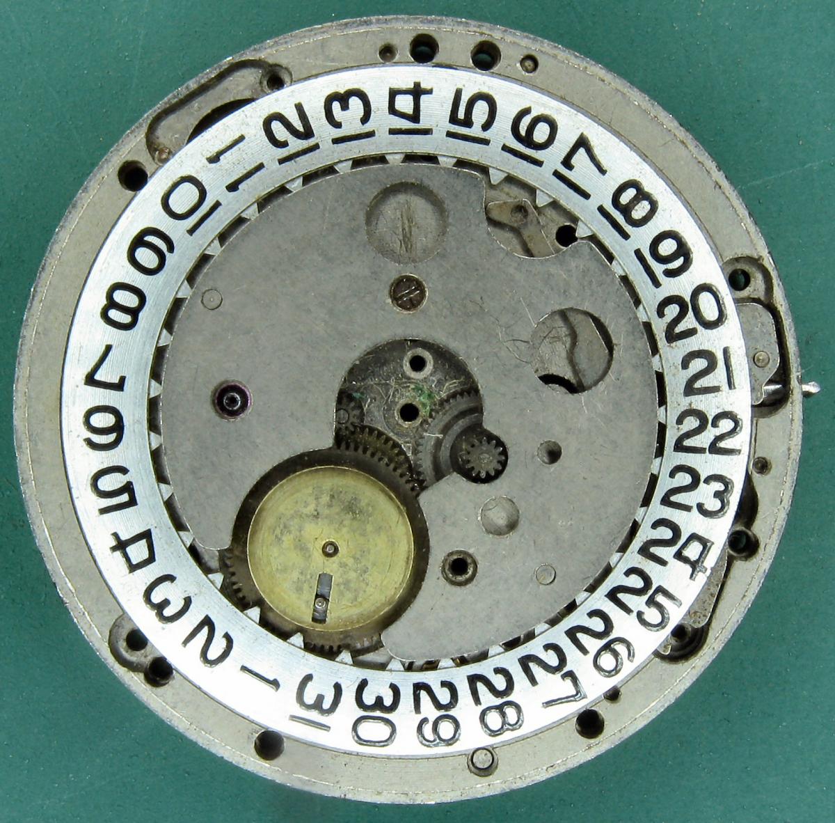
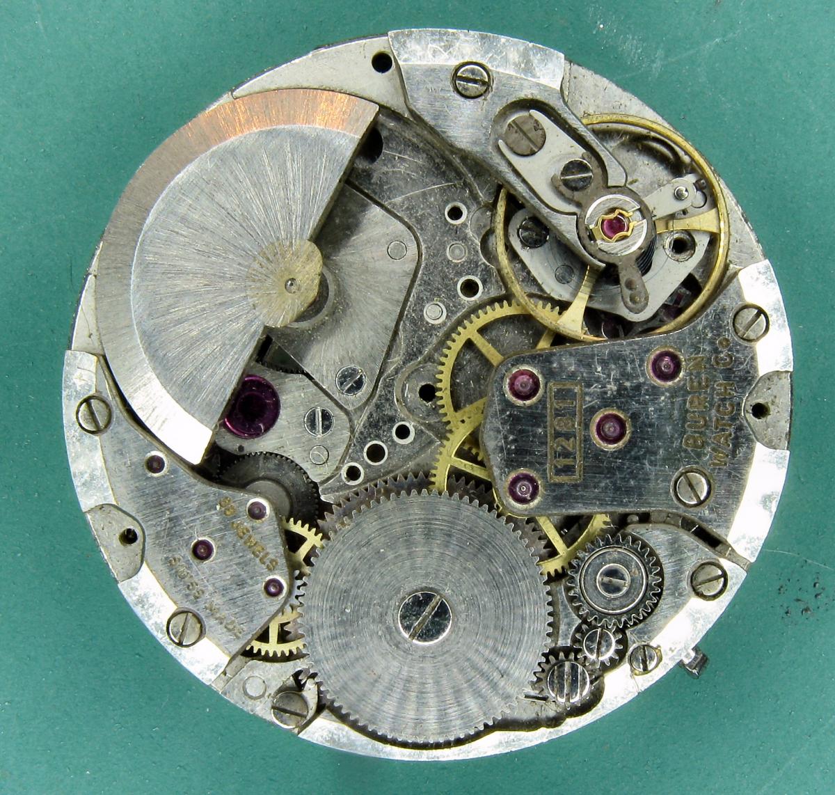
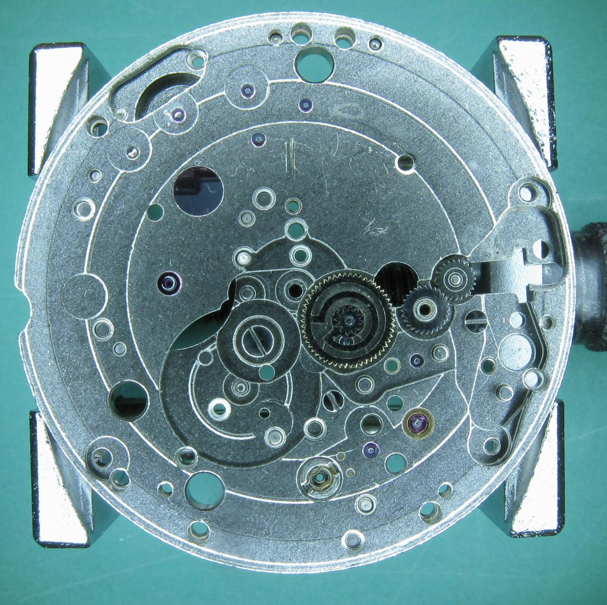
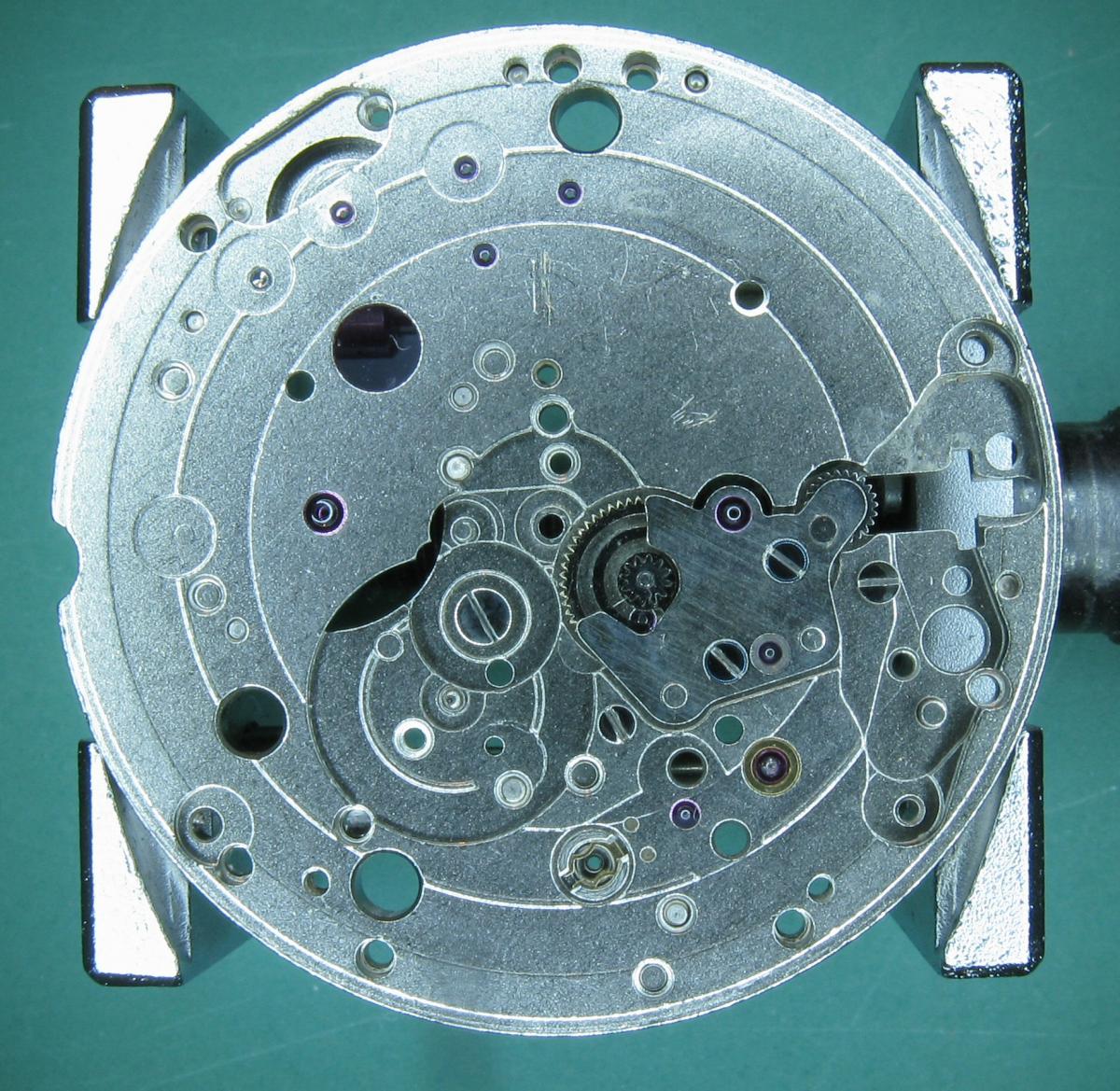
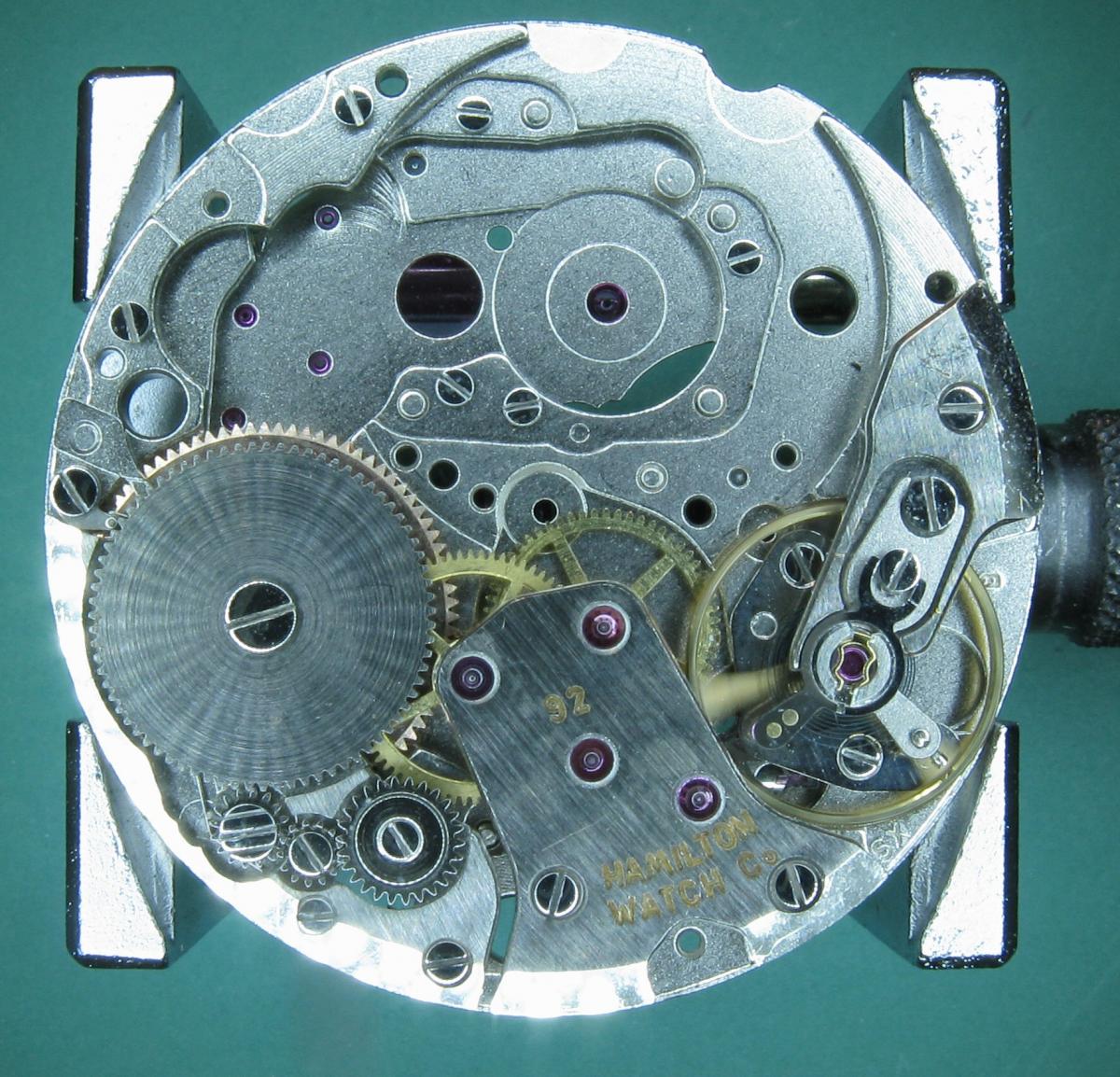
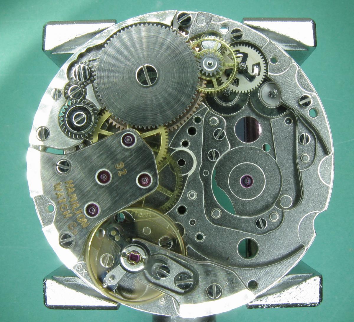
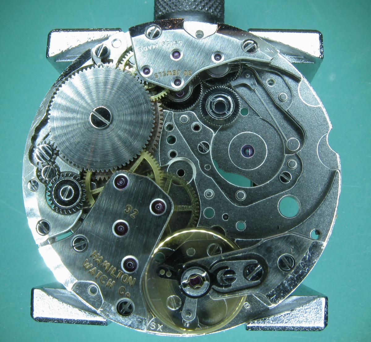
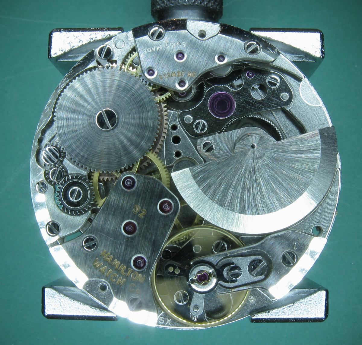
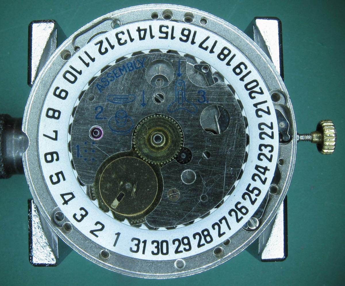
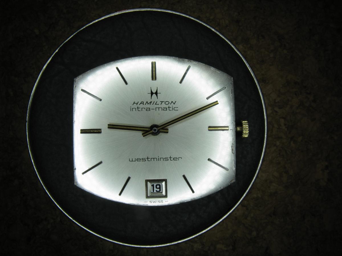
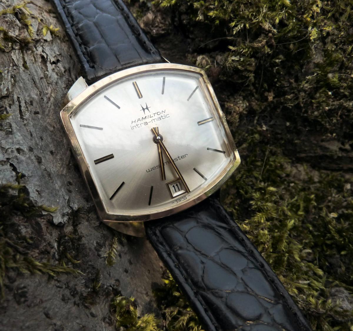
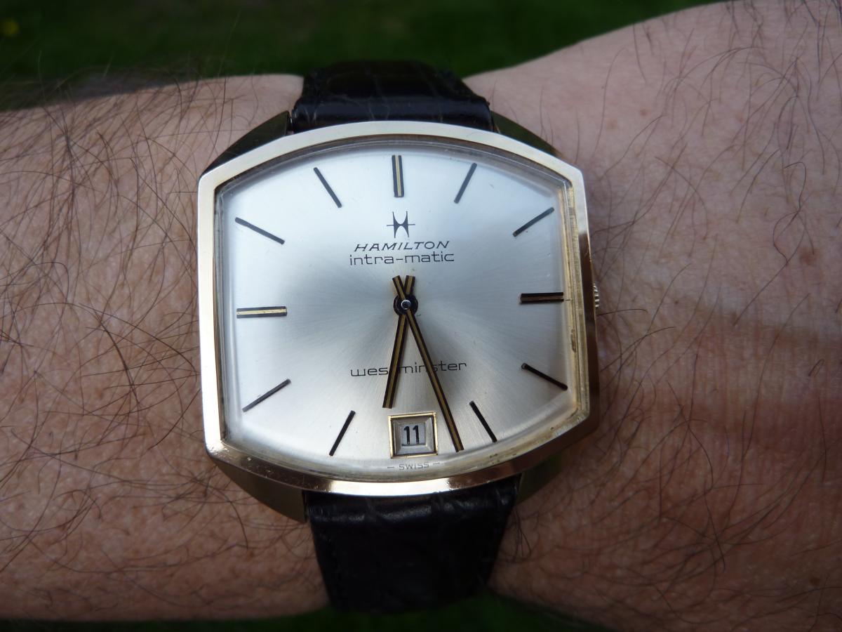
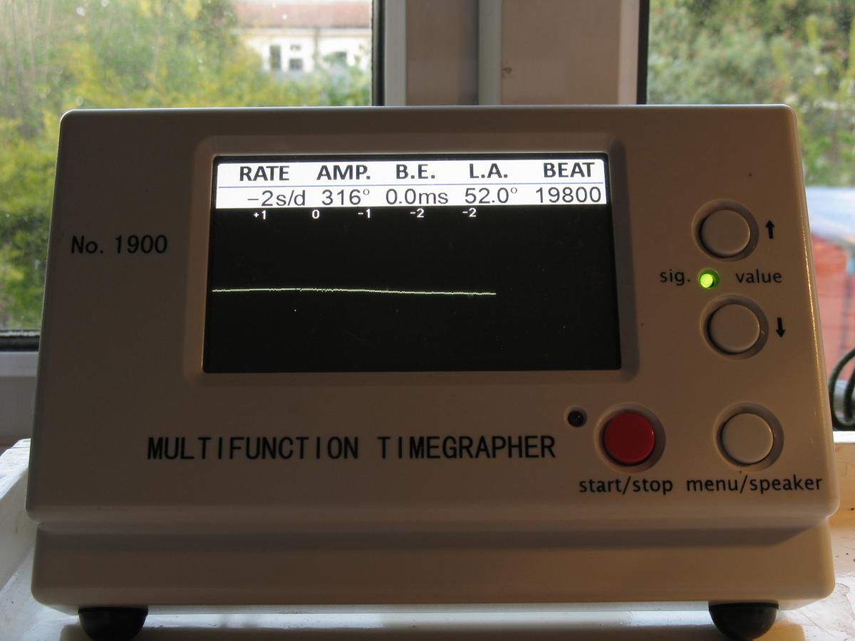
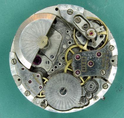
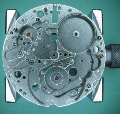
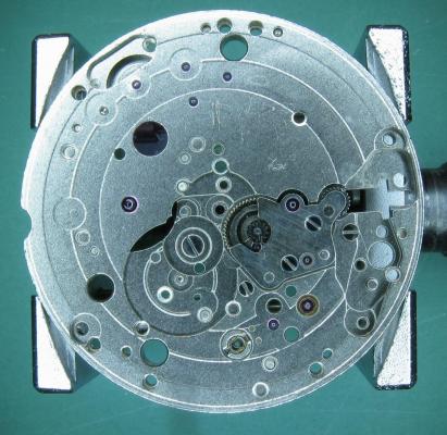
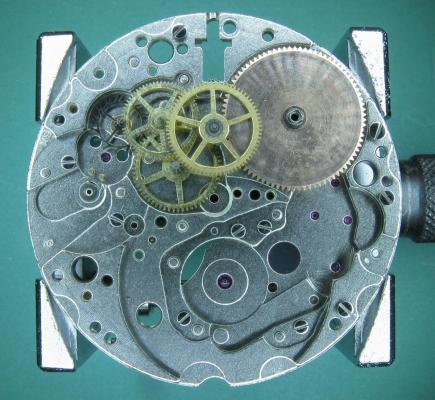
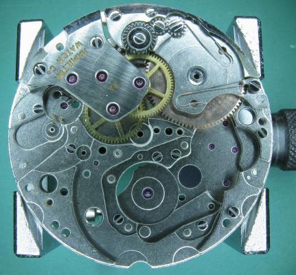
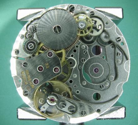
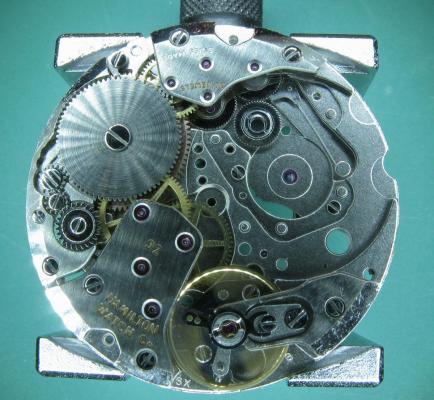
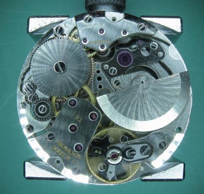
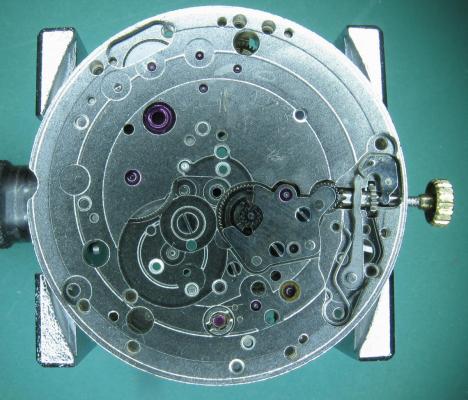
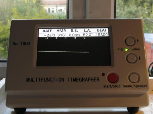
This is what I got up to over the Easter break. It was a project that I bought as a box of bits for a few quid about 4 years ago because although I had no idea what it was (the listing didn't say), it looked interesting and I fancied the challenge. It turned out to be a Hamilton Intra-Matic Westminster which the previous owner had tried to "fix", got as far as dismantling, and given up on. Cosmetically it was in good order but mechanically was not good. The rotor pinion had lost its bottom pivot, as had the second wheel (centre wheel in a more conventional wheel train). And because it had spent some time rattling around loose in the box of bits the hair spring was in a poor state, and what had me really stumped when it came to working out how it all went back together was a large and rather complicated looking wheel and pinion assembly for which I simply couldn't find a home. Any way, it was put to one side until I could track down a donor for the parts and to hopefully show me where the "spare wheel" went. The movement is a 30 jewel Hamilton 92 micro-rotor, which is a re-badged Buren 1281. Unfortunately (for me) this has been used in a number of higher end autos and also as the base movement in some big name modular chronographs because of its thinness, which means that they tend to hold 3 figure values even as spare parts donors so it took a while for me to track down a suitable candidate at the right price. However, I did manage in the end to nab one for just over £30 and it arrived at the beginning of April, so the fun could begin. No strip down on this one as the Hammy came to me fully dismantled, here is the donor as I got it. It's a Buren 1281, a bit grubby with some missing screws, and the minute hand pinion has seized onto the centre post. I later discover that the canon pinion (which is actually on the second wheel pinion) is loose and I reckon that someone had diagnosed the loose canon pinion, had tried to correct it by tightening what they thought was the canon pinion, which was in fact the minute hand pinion, onto the centre post, over did it, and caused the whole thing to seize, hence spare parts movement on eBay!!! I stripped out the second wheel (complete with canon pinion which I tightened), rotor pinion, balance and hair spring, and the main spring (which was in better shape than the Hammy one), and then put the parts through the cleaner; the Hamilton 92 parts had already been cleaned. And here we go with the good bit. The Hamilton 92 main plate; cleaned and ready for reassembly. I usually start with the wheel train when I build a movement back up but that's not possible here because the motion works bridge also carries the lower pivot jewel for the second wheel, so the motion works have to go in first. With the bridge in place you can see the pivot jewel in between the minute wheel and the intermediate wheel. The movement is flipped and the wheel train and barrel (cleaned and greased main spring, and braking grease on the barrel walls) are positioned. Train bridge and barrel bridge installed complete with crown wheel and intermediate winding wheels. At this point the end shake on all of the wheels was checked and the general free running of the whole train tested, then the pivots oiled. The ratchet wheel in place, the pallet fork installed and the escape wheel teeth / pallet jewels lubricated. The balance dropped in and off it goes. Then the auto winding reversers and reduction wheels go in. The three armed spring on the first reduction wheel is a ratchet which prevents the rotor from helicoptering during manual winding. Unfortunately it also gives the crown a very gritty feeling when you hand wind which takes a bit of getting used too but it is normal. Bi-directional flip-flop (for want of a better term) gear and auto wind ratchet in place. Cover plate on and the micro-rotor assembly installed. Turning things over again the keyless works go in. Then the calendar works, date wheel, and cover plate. Before the dial and hands go back on. Confirmation on the Timegrapher that all is well. The obligatory wrist shot. And something more formal for the album :-) This is now an absolute favourite of mine and has a permanent home in my collection. It took a lot of waiting to get the donor but it was well worth it. The watch has been running continuously since 11 April kept wound from wearing it when I get home from work in the evenings and at the weekend, and has remained within a few seconds of reference time. And the "spare wheel"..... was precisely that, it didn't belong with the box of parts that this project started out as. I do hope the seller didn't miss it :-)


 2 points
 -
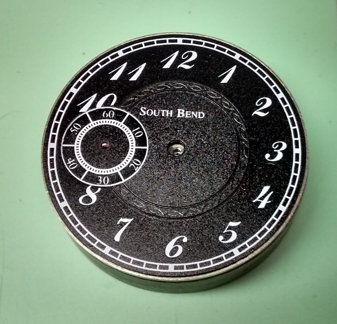
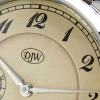
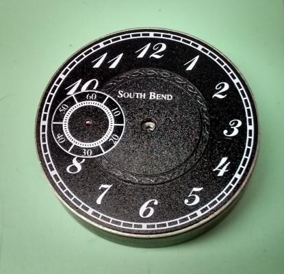
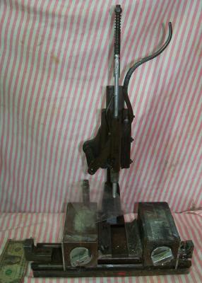
So it's been a few months since I posted here...but I've been regularly checking in. Hi Mark and Geo! So as a few of you know, I have a hobby of building watches. The one thing I hated was relying on some of the very few companies that actually print dials. Here is the USA there are only a handful that do this type of work! I was lucky enough to find an antique dial printing machine on eBay. It was just a vessel to move the dial from printing plate to paint application. I found a willing company to "Fill in the Blanks!" I won't name them here because I don't want to seem like I'm Selling this company! Anyway, they were a very big help when it came to me having questions. The sales, engineering and billing staff were first rate! They helped me pick the proper printing pads, helping me design and then produce my printing plates and then help me choose the proper ink and also recommended how to prepare the inks, pads and thinners to get the best results! So, here I am....First try at printing a dial.... I designed the dial myself using a free online software. The dial is printed in 3 stages. The first step was printing the hour chapter. Then, the second step was to print the sub seconds chapter. Lastly, I printed the name of the manufacturer that I will be using for this build. This was more of a proof of concept to me...Now, I can't wait to try new designs and styles! And, Now I have more control of what I build! That's very important to me...Cheers!
 2 points
 -
Just uploaded a new video. this one concentrating on correcting beat error.
 2 points
 -
That's what I use for a normal haircut! :)2 points
-
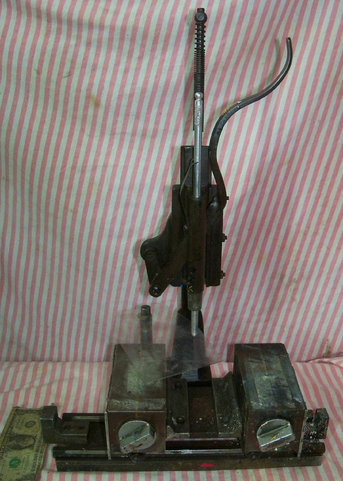
I bought an antique pad printer of the bay yesterday. It was the only such device specific to watch dials for sale, so I made an offer and it was accepted. Hopefully, it will help me do what I want it to do, print my own dials. I also found a company who makes laser engraved printing plates for pad printers that should work with this setup. I know it looks pretty beat, but like most tools from this era, it should still have some life in her yet! The dolly slides from one side to the other allowing the pad to pick up the paint from the etched plate and stamp the dial on the opposing side. The two surfaces are magnetic and are controlled by the 2 mechanical silver colored knobs. I'm thinking a 2 axis clamp on one surface and a rotary table on the other. This way I can fine-tune the position of the printing plate and watch dial. Sounds good in theory!
 1 point
 -
I think I'm right in saying that if the hair spring coils are properly concentric and the terminal curve (the bit that goes through the arc made by the regulator curb pins) is circular rather than spiral, the moving the regulator shouldn't introduce any beat error. If the regulator curb pins impinge on the spiral part of the hair spring, or if the terminal arc of the spring is not circular, then as you move the regulator the curb pins will interfere with the concentricity of the hair spring which possibly could introduce or exacurbate beat errors.1 point
-
Don't get discouraged! I'm still in the beginning phase myself. When I first tried to put on a train bridge it took me forever--now it only takes me forever minus 1. But I'm improving. I use an old oiler to move the pivots into their jewels while applying a very slight pressure with my forefinger. One has to be careful not to bend the pivots in the process--which I've also done. But that gives me a chance to use my staking tool! For me, the most difficult one to set is the escape wheel (unless it has its own bridge which I've encountered a couple of times). Awhile back I had lunch with a very experienced watchmaker of 25+ years who works on very high-end watches. At an early point in his career he started to work at Breitling. He told me that there, he broke watches for two years before he started to get things right. He said he appeared regularly at the Breitling parts supply room and it was the virtually inexhaustible supply of parts available for "do overs" that allowed him to develop. I found this very heartening and it has propelled me ever since. I'm no longer afraid to break things! (I try not to, of course.) But for me the greatest psychological block I've had to overcome is the fear of breaking something. When I break a watch I'd really like to keep I make up a set of notes to remind me of what went wrong and put it away until my skills improve or I get the necessary tool or part to try again to fix it. One thing I've been doing is getting cheap but fixable watches and movements from eBay, flea markets, pawnshops, etc. Not only does it give me a chance at fixing them but I've encountered a large variety of movements--most of which I've never heard of. It allows me to see commonalities and differences and it's my equivalent of Brietling's supply room.1 point
-
Mark, your series is coming along beautifully. I too can't wait for more! Cheers, Bob1 point
-
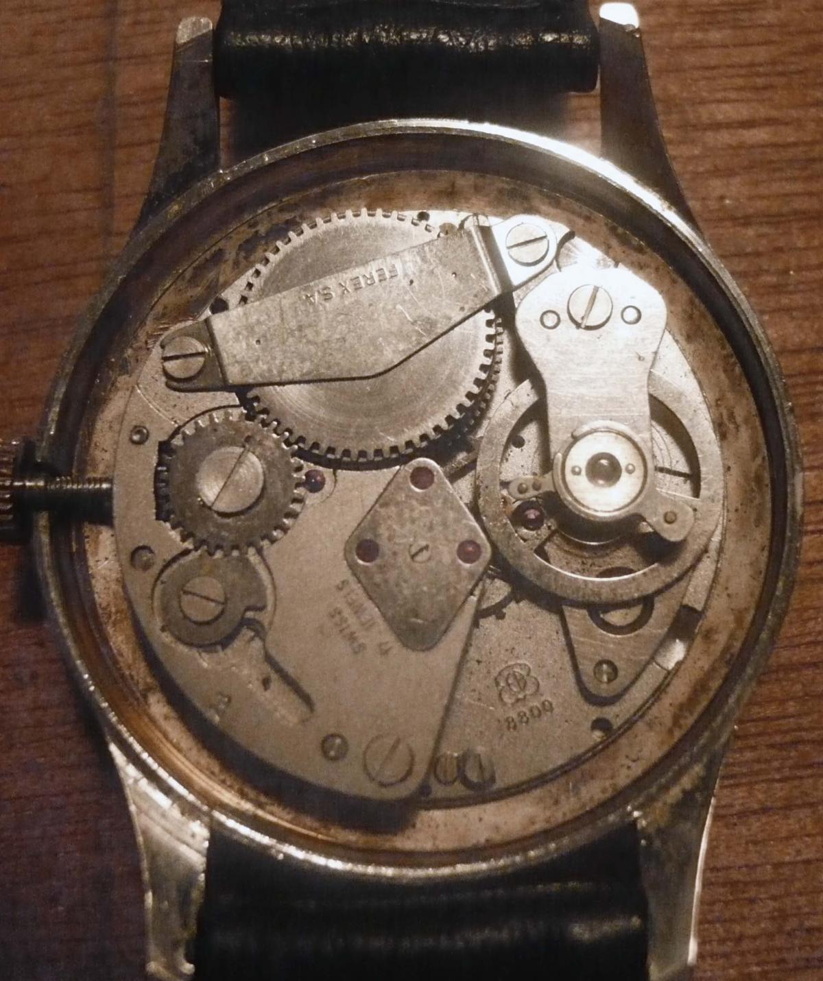
Thats a nice clock Ro63erto, and I remember you posted before with pics of the dial--very nice. John that's a nice little machine there! I call most mechanical things "machines" although I know it is really an instrument (device that measures), and not a machine (device that performs work). The Ebauche Bettlach 8800 is another of those pin-levers that seems to have great durability, as can be verified by the numerous examples still working and getting wrist time. I have some in my collection with 17 jewel and 1 jewel. The version you have seems to be a little older than some I've seen because it does not have the KIF shock system usually employed. This is the main area of weakness, so hopefully little Roma will be explained to guard against dropping or bumping his vintage timepiece! The other place I've seen trouble is the pin lever itself, which can sometimes become bent (one of the pins) and throw off the beat error. I place a tiny little drop of Moebius 941 on each pin to help smoothen the engagement of the escape teeth with the pins. Try not to put too much or the lop-sidedness will result in a "snow storm" on the timegrapher. By the way, I have many spare parts for this movement as well, and my offer applies here too. I like to see pin-levers getting some attention. Joe1 point
-
:) I understand - I have had a huge amount of requests for regulating and timing machine content. So it is good to create a mixture of basic and advanced content but at the moment I am doing a series on the basics and will work up from there because it is laying foundations for some of the examples you would like to see. I really appreciate the feedback Bogdan :)1 point
-
Ah I see your problem. Using vernier callipers measure the diameter of the broken one. Order two new ones, one the same size or 0.01mm larger, and also order the next incremental size up. One of them will fit, but you will need to have a crystal lift to compress the new crystal to allow it to enter the case.1 point
-
Sounds like you found a jeweller/watchmaker worth returning to.1 point
-
This is my EB8800 movement but its in a 45+ year old Jaguar desk clock. Took it out of its leather case for the first time in 30 years, gave it a wind and is working perfectly.1 point
-
Good catch Bob ! That back had me fooled for sure ! I was pretty sure it was a screw on, my Swiss Army watch has the exact same type of back, but it's a screw on !!!! Same brand, same back, even same movement !!!1 point
-
Your call was spot on Bob! :)1 point
-
These bite-sized video tutorials are great Mark. Essential viewing for those like me who've not spent much time around watches or watch forums.1 point
-
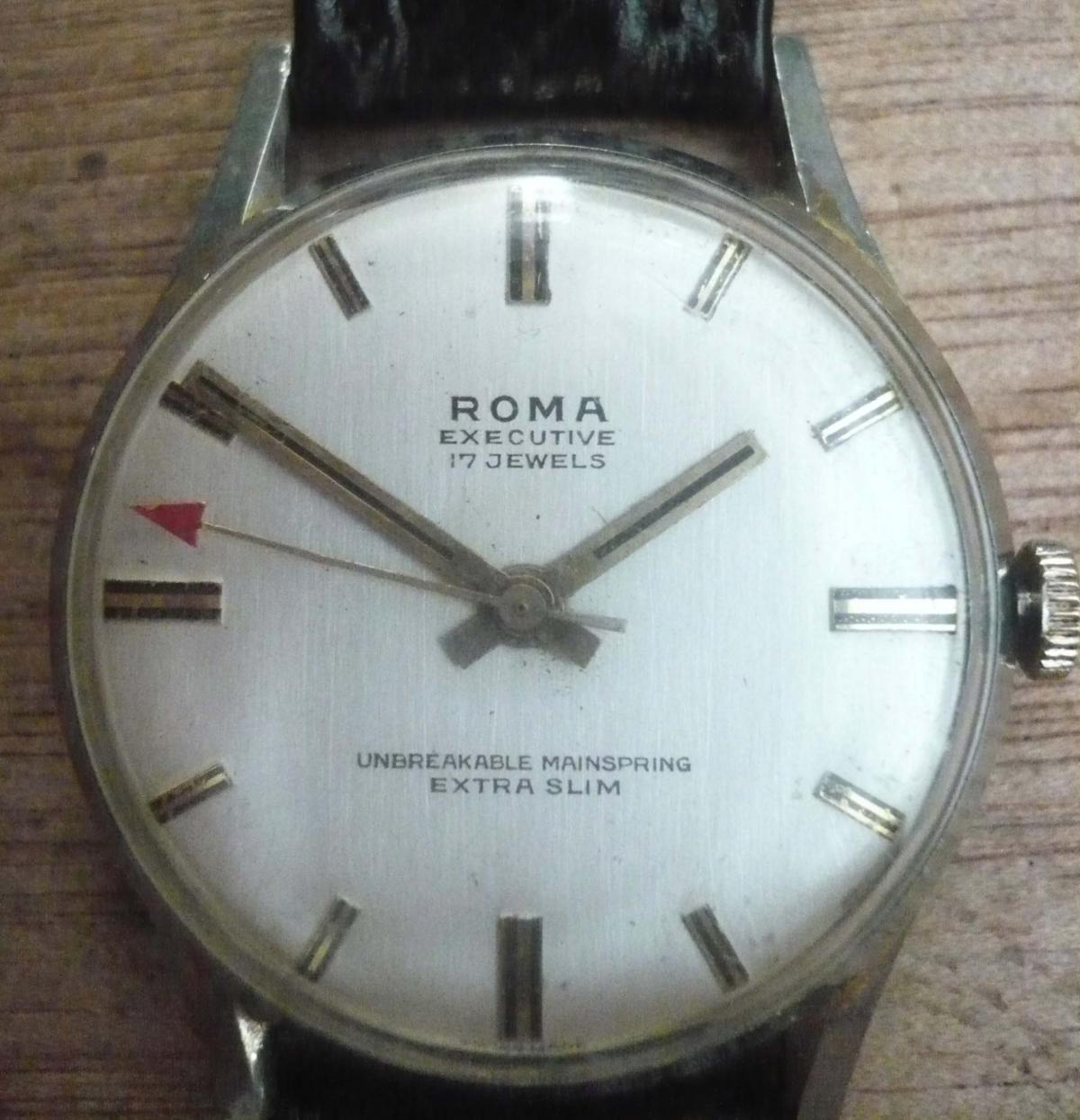
Here's my Roma Executive. I think the back must have been off a few times as you only need to blow hard and it comes off! When all's said and done though, it's not a bad looking watch so with a good clean and oil it should soldier on for a week or two.

 1 point
 -
Hey anilv thanks for the response. I've since looked on the omega vintage watch dbase & found its defo a deville case. I think your probably right that it will look odd with that dial. TBH I'd like to keep it stock with a Gen deville dial, but until I can find one I may put the geneve dial in it & get the hour markers plated.1 point
-
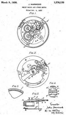
There is a copy of John Harwood's patent on the web but it has been produced by a character recognition program and has lots of errors. Here is my attempt to correct these errors. Everyone is welcome to add corrections that I missed, March 9 1926. J. HARWOOD WRIST WATCH AND OTHER WATCH Filed Oct. 8, 1923 patented Mar. 1926. JOHN HARWOOD, 0F BALDRINE, LONON, ISLE OF MAN. To all whom it may concern: Be it known that I JOHN HARWOOD, a subject of the King of Great Britain, and resident of Baldrine, Lonon, Isle of Man, have invented certain new and useful Improvements Relating to Wrist Watches and Other Watches, of which the following is a specification. This invention relate to wristlet and other watches, its object being to provide a watch with a self-winding movement whereby the need for any protruding parts through the case such as the usual winding stem is eliminated, the case being thus rendered practically dust and waterproof. Overwinding of the watch is also prevented, the likelihood of the main springs being. broken being thus reduced, and by-reason of the fact that the spring a under ordinary conditions would only run down say 9 to 12 hours, a more even torque is given to the train. As the setting of the hands in ordinary watches is effected from the usual winding stem which protrudes through the case and which in this invention is eliminated, means are provided in the present invention for setting the hands otherwise than by means of such stem. According to this invention, the winding of the main spring is effected by an oscillating weight pivoted within the watch, the oscillation of this weights when the watch is being worn turning a plate or member acts by means of a spring controlled click or pawl to wind the main spring, the frictional drag between the weight and the plate being ineffective to move the plate, and consequently further to wind up the main spring, when the winding force becomes greater than the frictional grip on the plate and in this way overwinding is prevented. The hands are set by turning the bezel in one or other direction, crown teeth on the underside of the bezel engaging and rotating a plnion, a pin on the stem of which engages a cam face on a crown gear.No ports or apertures are in the wall of the case. In the accompanying necessary drawings which illustrate the invention by way of example, Fig. 1 is a rear view showing the oscillating weight and friction plate for winding the watch, Fig. 2 is a front view under the dial showing the means for setting the hands and the front axis of the weight, Fig. 3 being a fragmentary detailed view of the crown ring teeth in the bezel, and Fig. 4 is a detail of the crown gear showing the cam face and friction spring for holding the crown gear. Fig. 5 is a radial section through the oscillating weight, friction plate and control spring, the parts being separated in order to show them clearly. The watch is fitted with a weight A of any suitable form but preferably more or less semi-circular, pivoted at the rear on an extension of the set hands arbor or centre pinion pivot B, spring buffers A' being fitted at each end of the weight to prevent knocking or shock to the watch movement during the oscillatory movement of the weight which movement is limited by two stops. A plate D pivoting about the same axis as the weight is frictionally connected to the weight A by means of a control spring E which is secured to the weight by two screws, one of which, F, serves to adjust the pressure of the control spring on the friction plate D and in this waythe frictional drag between the weight A and plate D may be adjusted. The friction plate D carries on its underside a pawl or click G which engages a ratchet wheeI, the spring H keeping the pawl G in engagement with the ratchet. Rotating with the ratchet is a pinion U which engages and drives the first toothed wheel of the winding train. It will be seen, therefore, that if the movement be held on edge and turned clockwise looking from the back as in Fig. 1, the weight A being at the bottom and at its left extremity, an anticlockwise movement will be given to the ratchet wheel I and its pinion U, the wheel I being held from returnig after movement by a second pawl or click J pivoted on the pinion K. In this manner the whole winding train is turned each time the wearer drops his hand and raises it again in the case of a wristlet watch. Overwinding is prevented by the action of the friction plate D which carries the pawl G, inasmuch as when the main spring is wound and its resistance to further winding thus increases, the friction plate D will be driven clockwise until ultimately it meets the cock C and as the fully wound spring offers resistance in the other direction, the friction plate will not return under the drag of the spring E but will remain stationary, although the weight may continue to oscillate under the movement of the wearer, the spring E riding idly to and fro over the friction plate D. The weight is carried at the back by a radial arm A and at the front by an arm A, Fig. 5, screwed to the weight. The front axis about which the weight pivots is shown in Fig. 2, an eye A in the arm A engaging a bush A on a plate X which bridges the hand motion works. In this way as the watch is being worn the weight oscillates to and fro about its pivots and by the frictional drag of the spring E on the plate D the pawl G is moved to and fro round the ratchet wheel I and so-winds up the main spring until such time as the further resistance of the main spring to winding permits the weight to oscillate idly, the spring E then merely riding frictionally over the stationary plate D. No protruding winding stem is thus required and the watch movement is thus completely enclosed. As, however, the winding stem has been eliminated someting other than the usual means must be provided for setting the the hands. This is effected by making the usual bezel rotate and turning it angularly forwards or backwards. Normally the set hands gear is out of mesh in the position shown in Fig. 2. On the inside face of the bezel, as shown in Fig. 3, is a gear ring formed of crown teeth J When the bezel is in position on the case these teeth J engage a pinion K mounted on a stem L and, loose on the stem L, is a crown gear M which is capable of longitudinal sliding movement on the stem L as well as rotary movement thereon. On the upper edge of the crown gear is a slope or cam face M engaged by a pin P in the stem L and from the higher portion of the cam face M a stop Q, projects. Resiliently gripping a groove in the crown gear M is a mug spring R, the radial end B of which is inserted into a hole in a a return lever S pivoted at S and pressed out by a spring T. The action of this return spring is normally to hold the crown gear out of engagement with the intermediate wheel 0 which engages and drives the motion wheels for setting the hands. When it is desired, therefore, to set the hands the bezel is rotated in one or other direction the gear which rotates the motion wheels to set the hands. After setting the hands, in order that the crown gear M may disengage from the intermediate wheel 0, the bezel is backwardly rotated through an angular distance corresponding to five minutes on the dial, this movement being sufiicient to bring the pin P back to the lowest point of the cam face M and permit the spring T to return the lever S taking with it the crown gear M by means of the spring R which engages the lever S. Considerable advantages accrue from such a construction of watches, for instance, owing to the fact that no parts protrude through open ports in the case the latter remains dust and waterproof. The watch shall be kept wound up. Overwinding cannot take place by reason of the merely frictional. connection between the weight and the plate D, and, therefore, all usual breakages caused through overwinding such as pulling out of barrel hooks, main spring breakages, breakages of keyless wheel teeth and barrel teeth are avoided. The prominent weakness in present day watch construction namely the need for bevel or crown winding gear is eliminated, while by eliminating any necessity for apertures in the watch case, at least 50 per cent of the stoppages usual in watches will be avoided, such stoppages in most instances being entirely due to the presence of dust, grit, or to overwinding. I claim: 1. A self winding watch comprising, an oscillating weight, a pawl carrying plate frictionally connected to the weight, and a pawl on said plate adapted to be moved by the oscillations of the weight to turn the winding train. 2. A self winding watch comprising, an oscillating weight, a pawl carrying plate frictionally connected to the weight, said weight and plate being pivoted about the same axis, spring buffers on the weight engaging stops at each end of its travel, the bezel then positively turns the crown, and the plate being pivoted about the same axis is normally sufficient to wind the main pawl on said plate. In testimony whereof I affix my signature JOHN HARWOOD.
 1 point
 -
I believe it is a pressure back not a screw in...they do that sometimes to mimic more expensive watches. You'll find inside a regular Ronda 515 movement (if only a date dial). I believe if you try Rolex type dies to open it you will find none of them fit...because it is not a screw on! Hope this helps. Cheers, Bob PS. I believe there is an indentation on the case to fit the knife. You will need a press to close it back!1 point
-
OK - I'm jealous, I want a blue basket!!! Mine is boring grey. :D Top tip: If you ever need more of the little baskets (you can never have enough IMO) then I usually buy them from this guy - quarter of the price of Cousins: http://www.ebay.de/itm/Siebkapsel-z-B-fur-Elma-Reinigungsmaschinen-/141412294943?pt=Uhrmacherwerkzeug&hash=item20ecd4611f1 point