Leaderboard


Popular Content
Showing content with the highest reputation on 06/11/15 in all areas
-
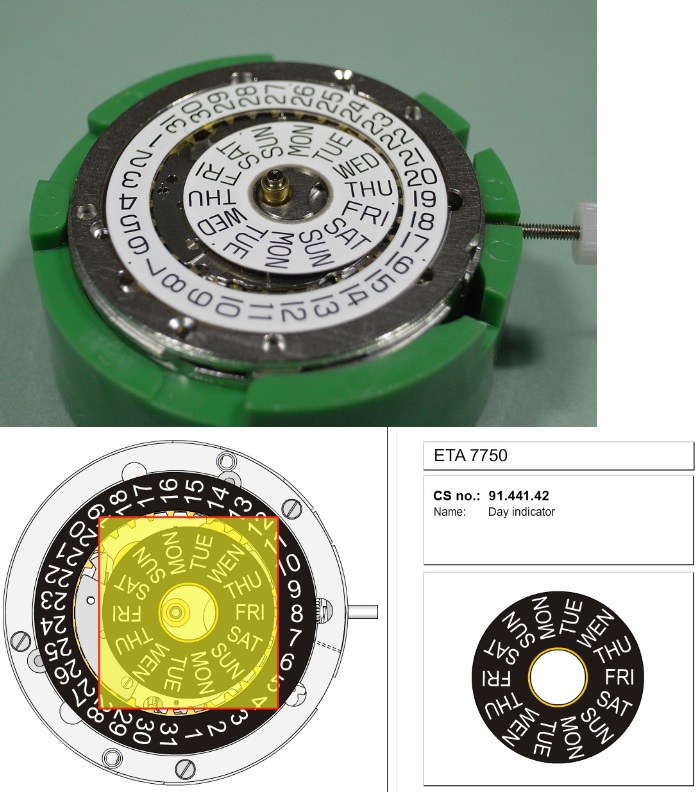
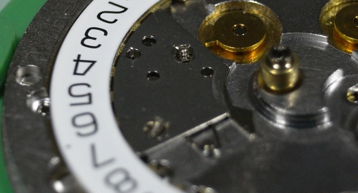
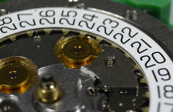
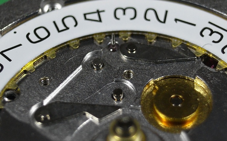
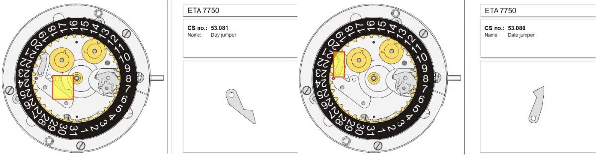
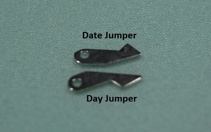
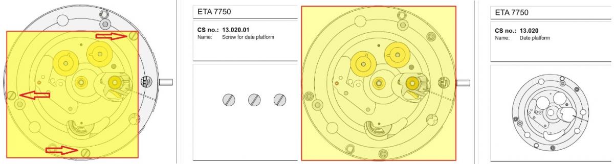
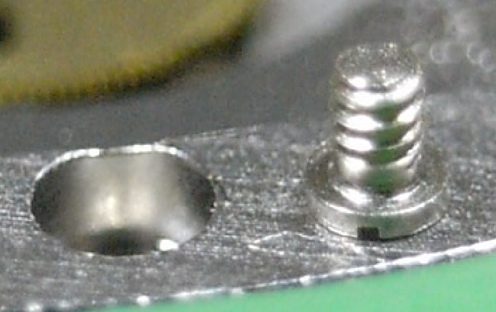
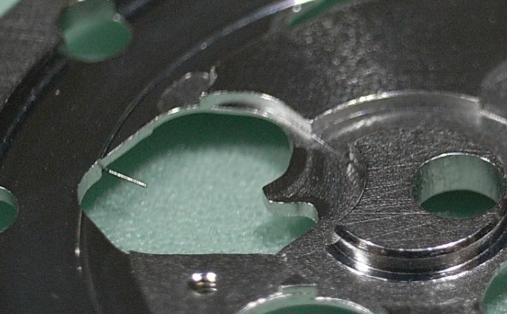
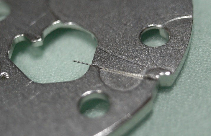
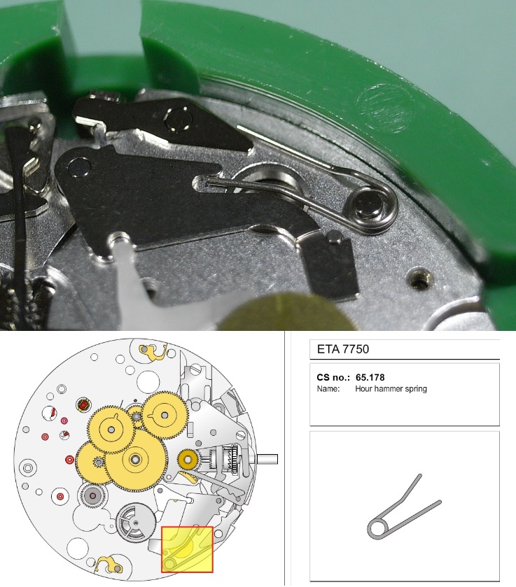
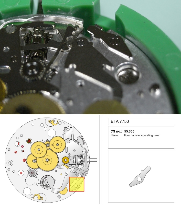
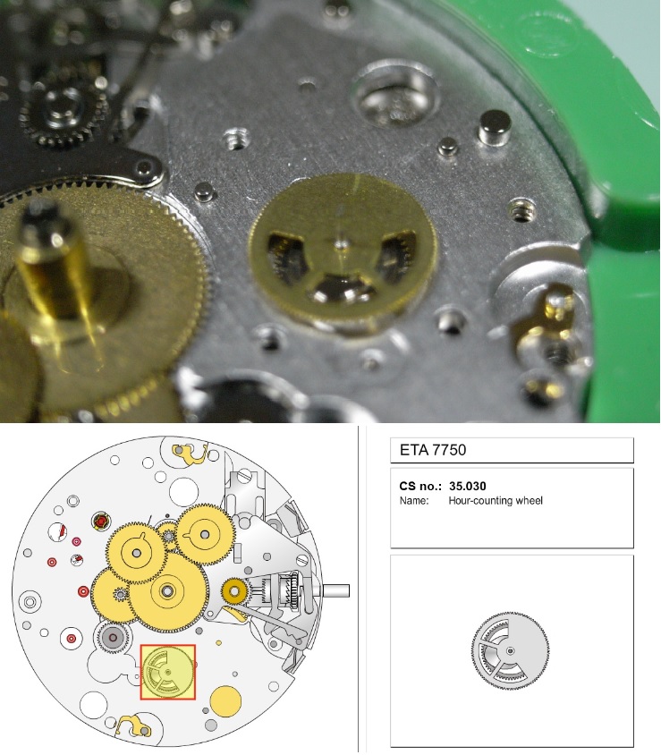
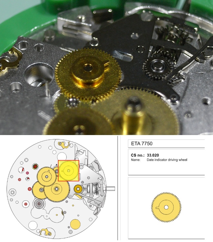
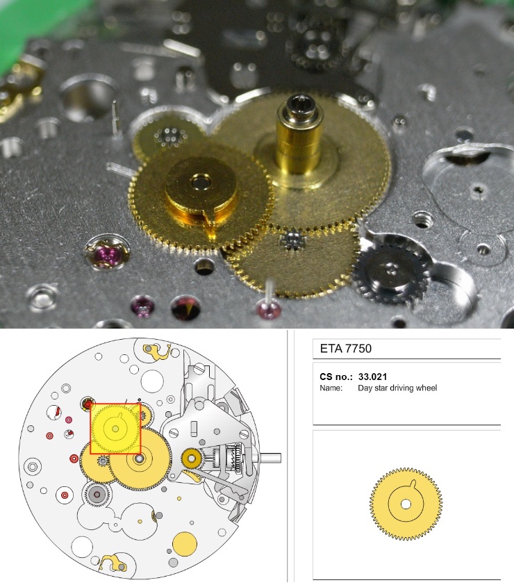
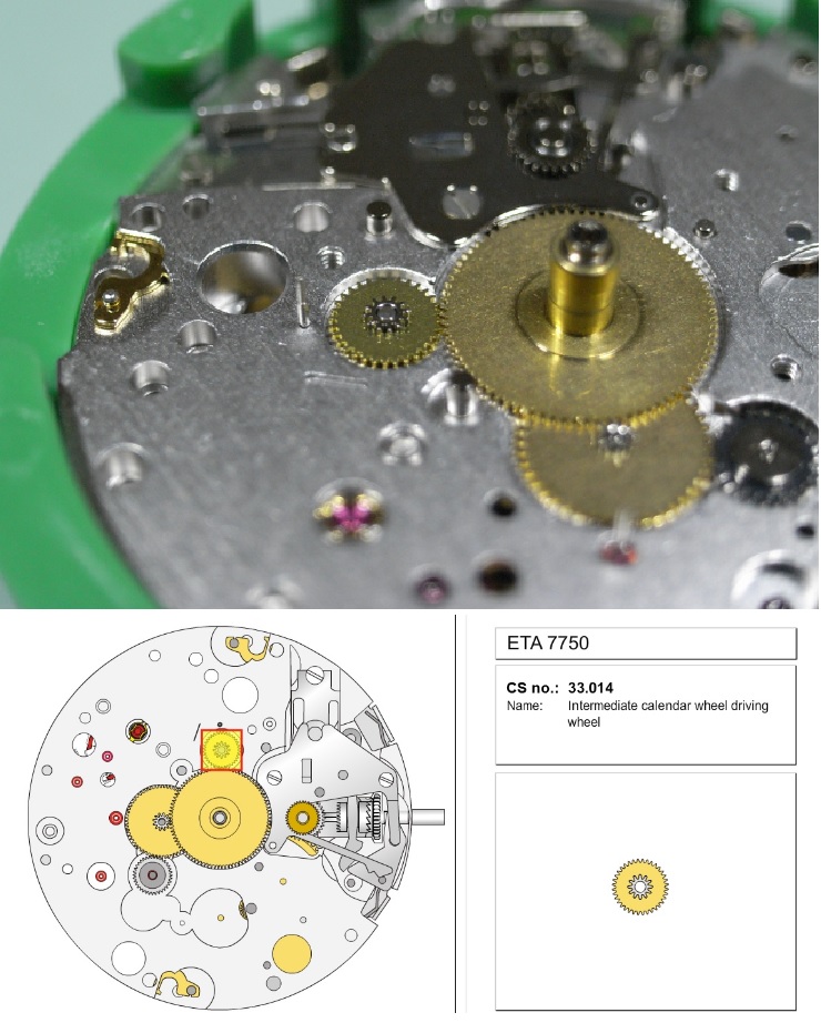
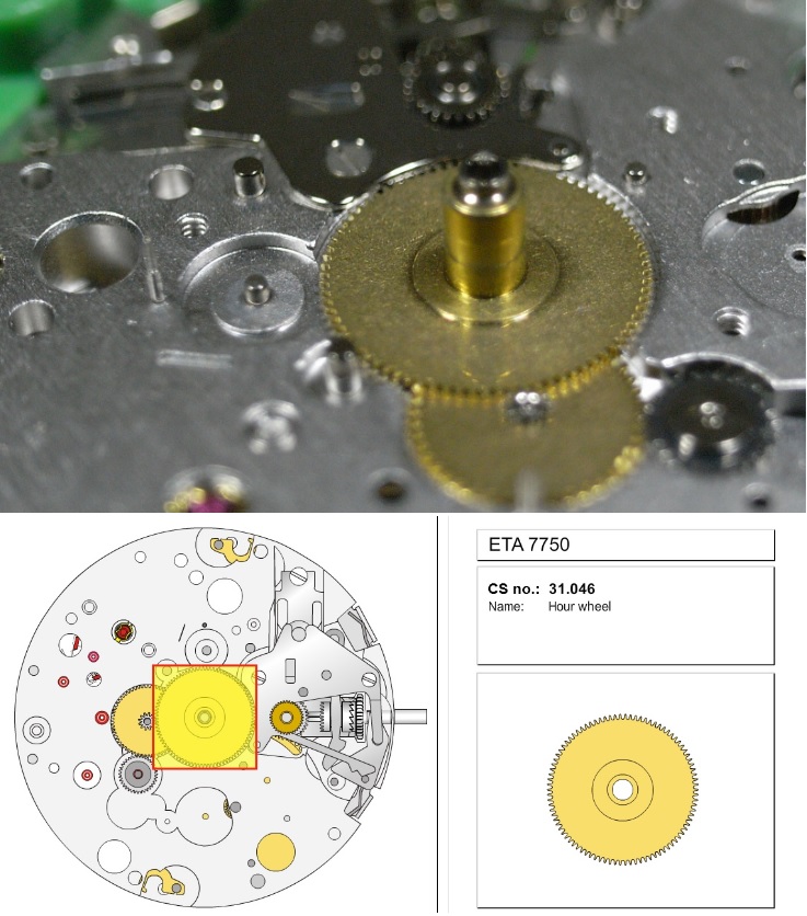
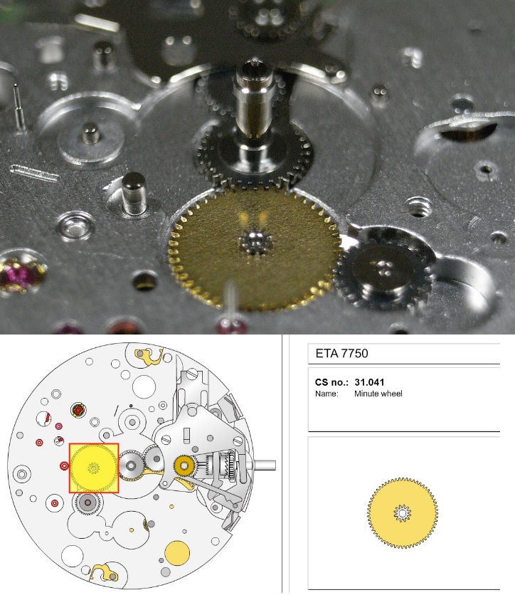
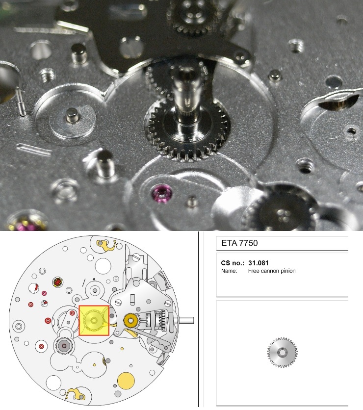
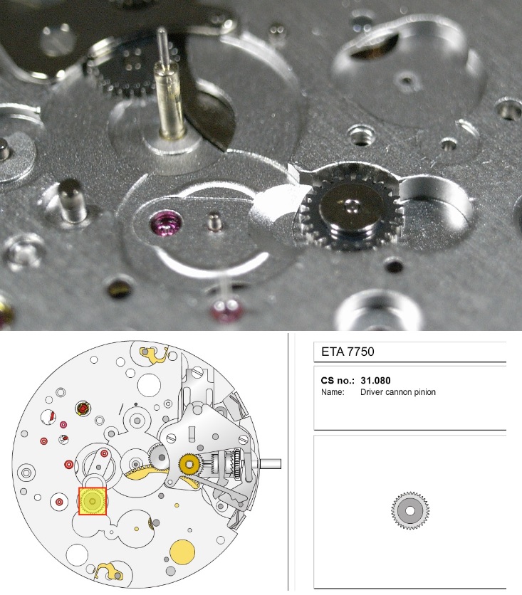
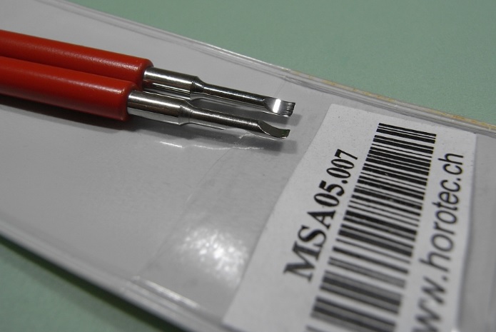
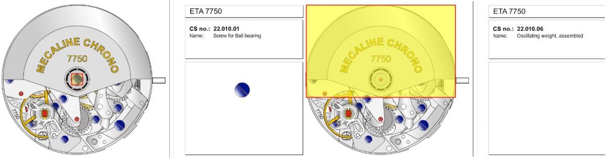
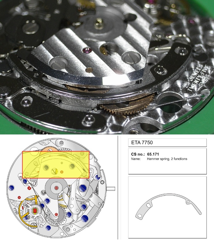
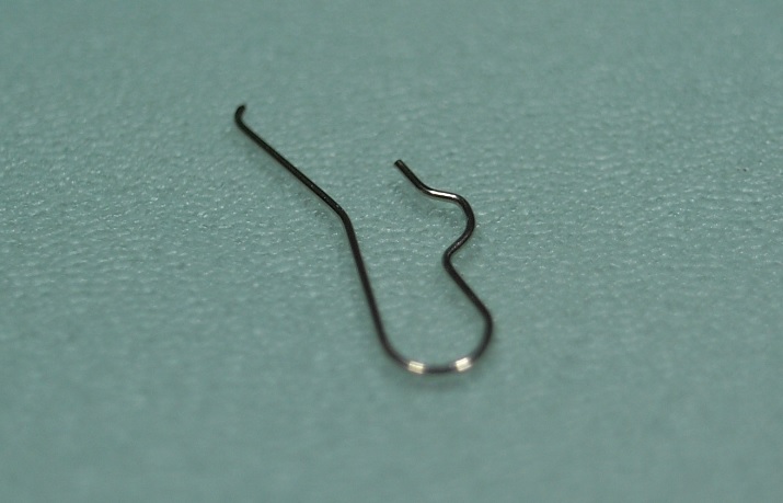
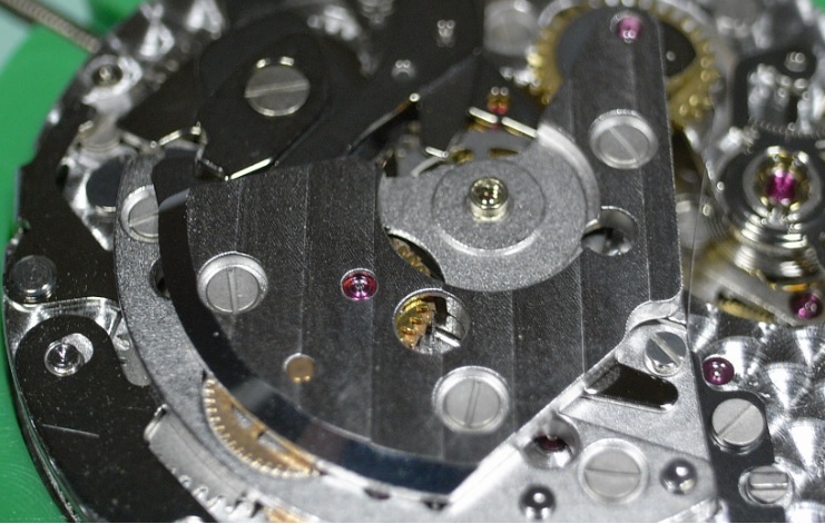
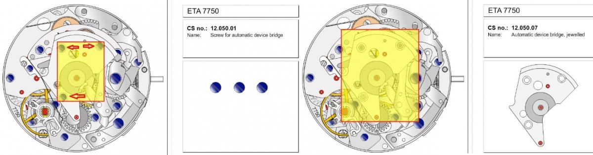
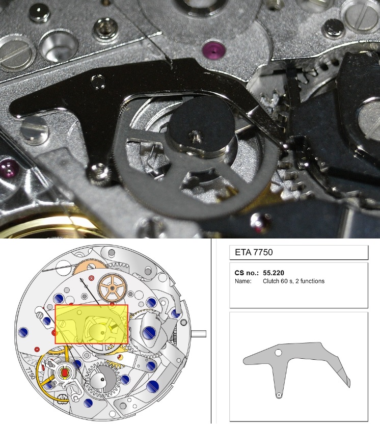
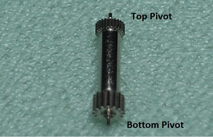
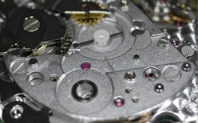
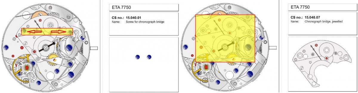
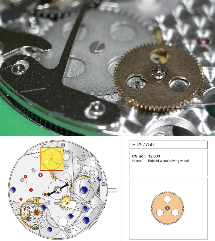
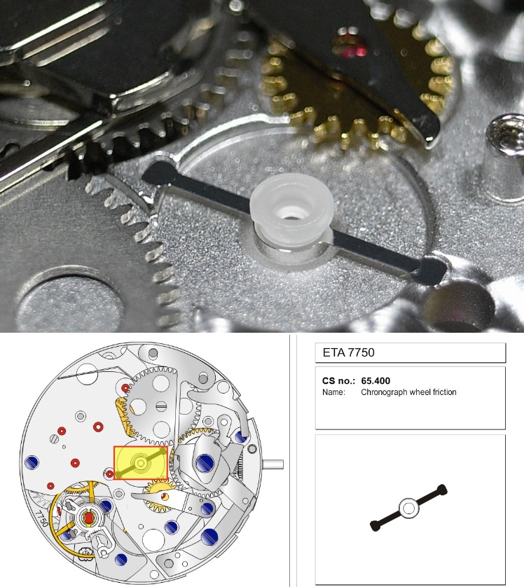
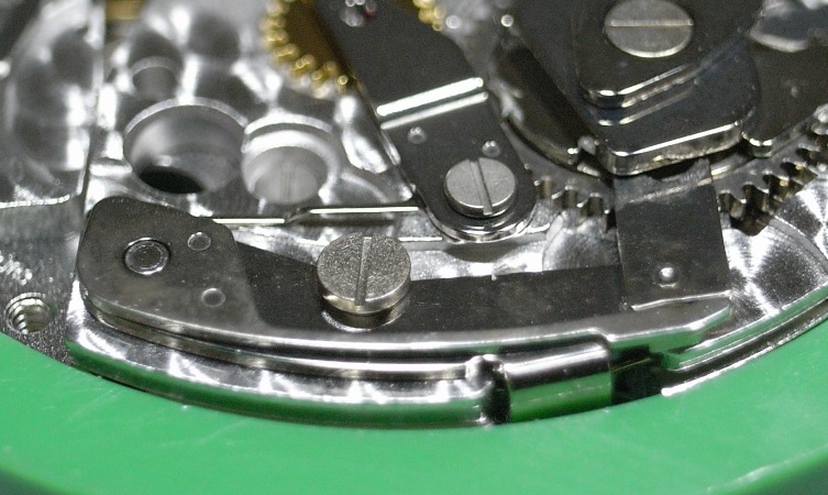
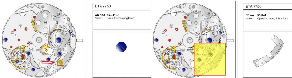
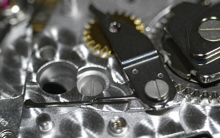
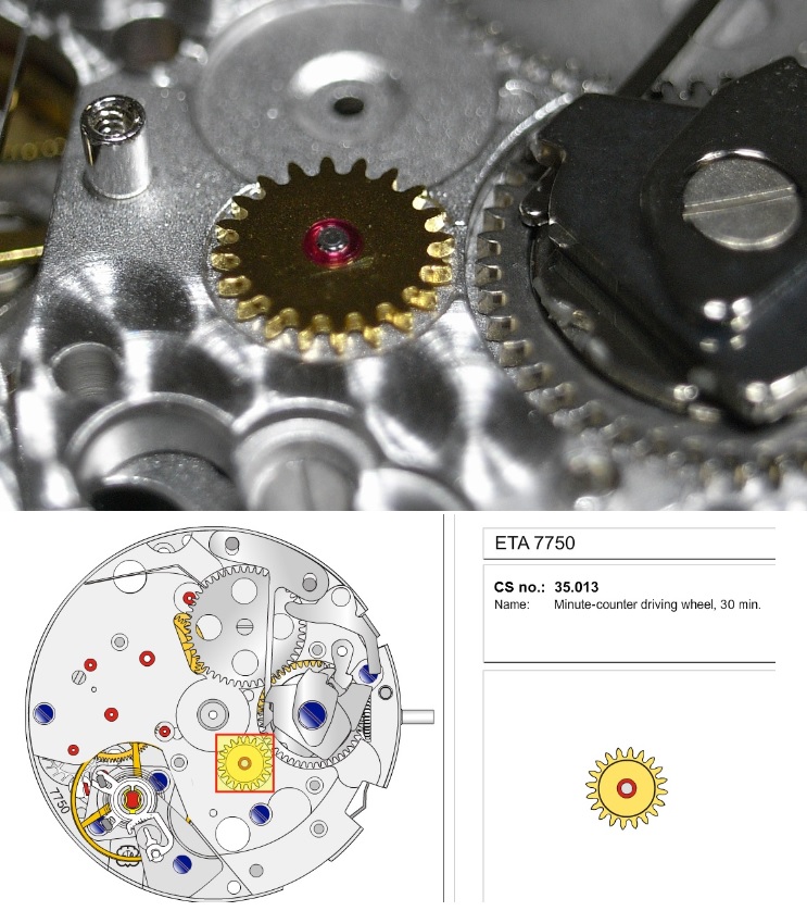
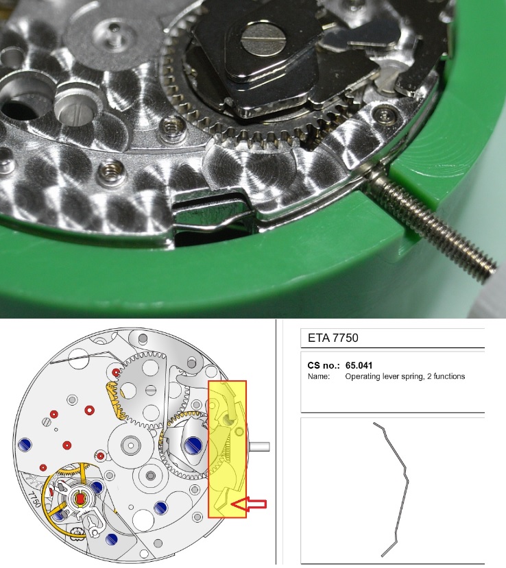
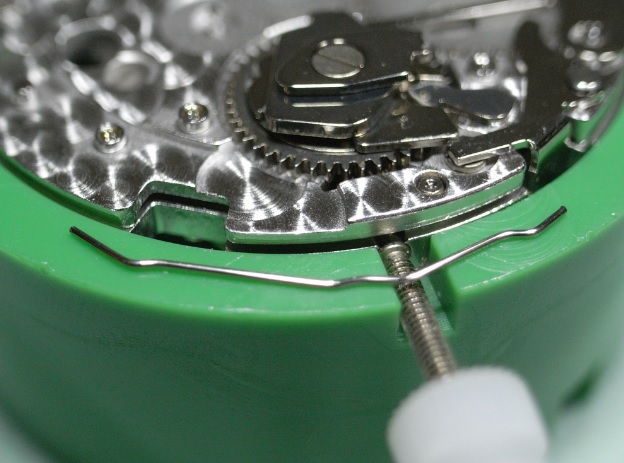
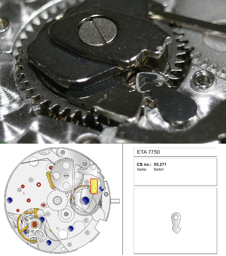
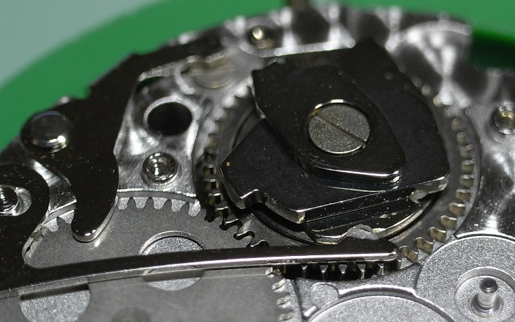
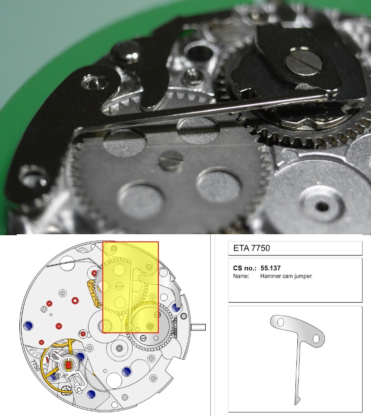
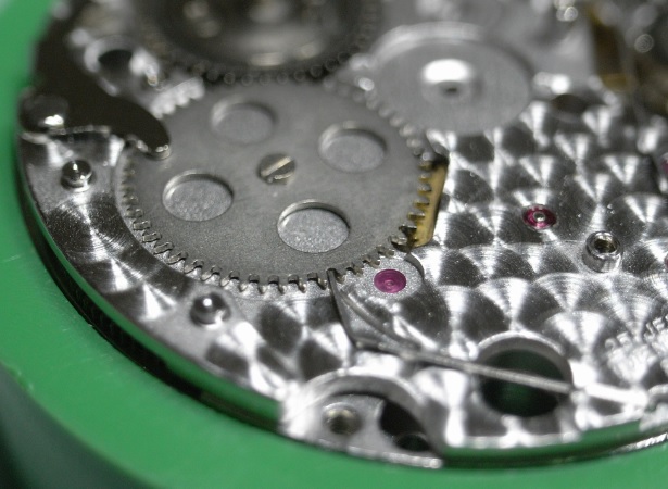
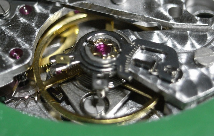
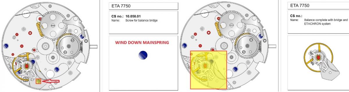
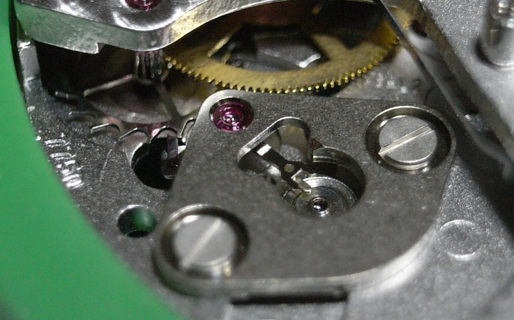
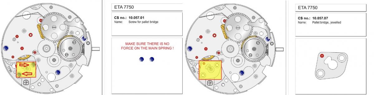
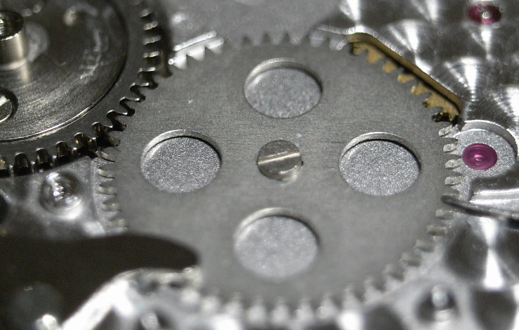
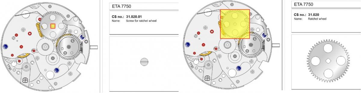
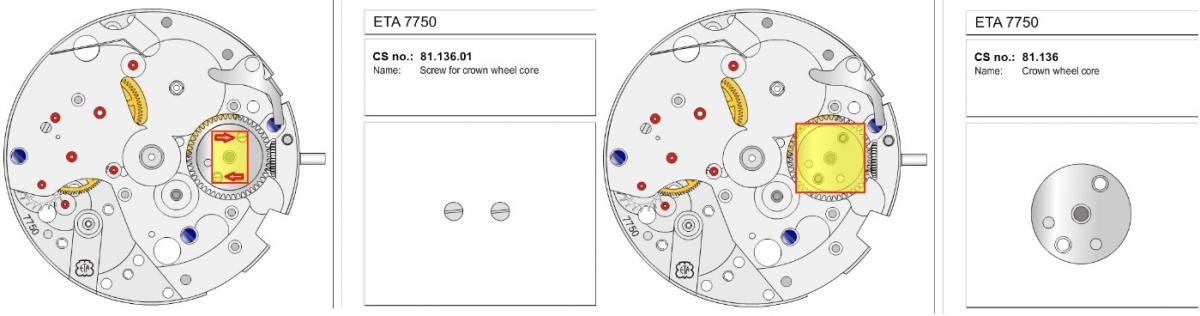
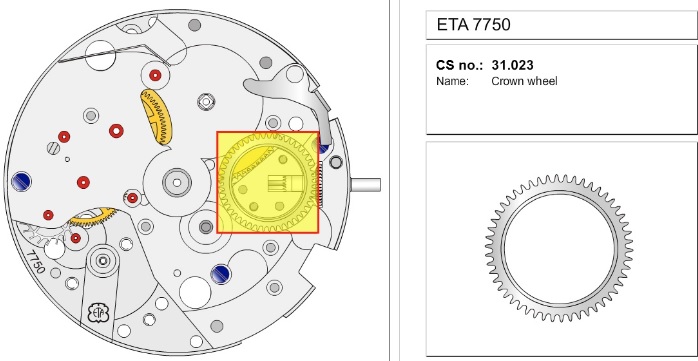
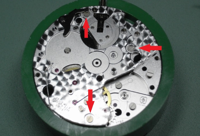
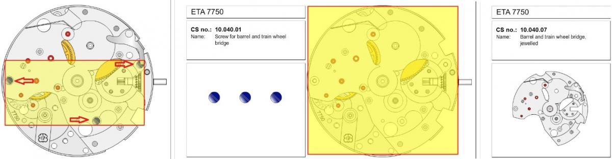
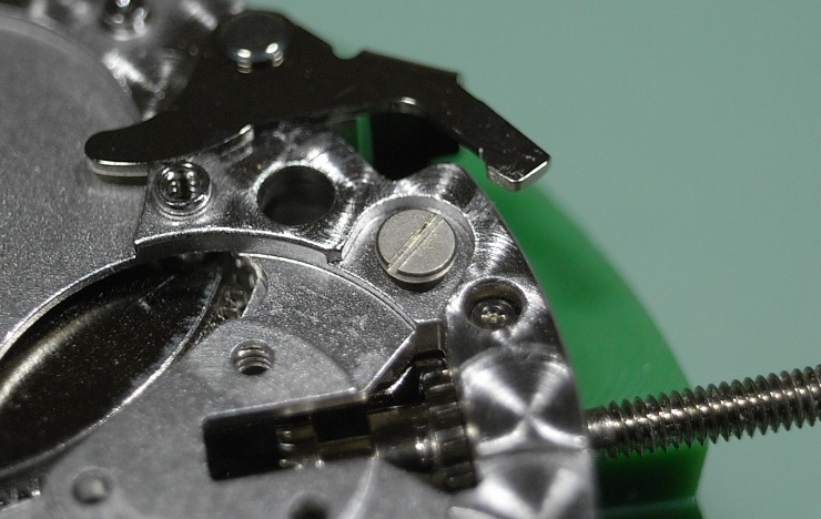
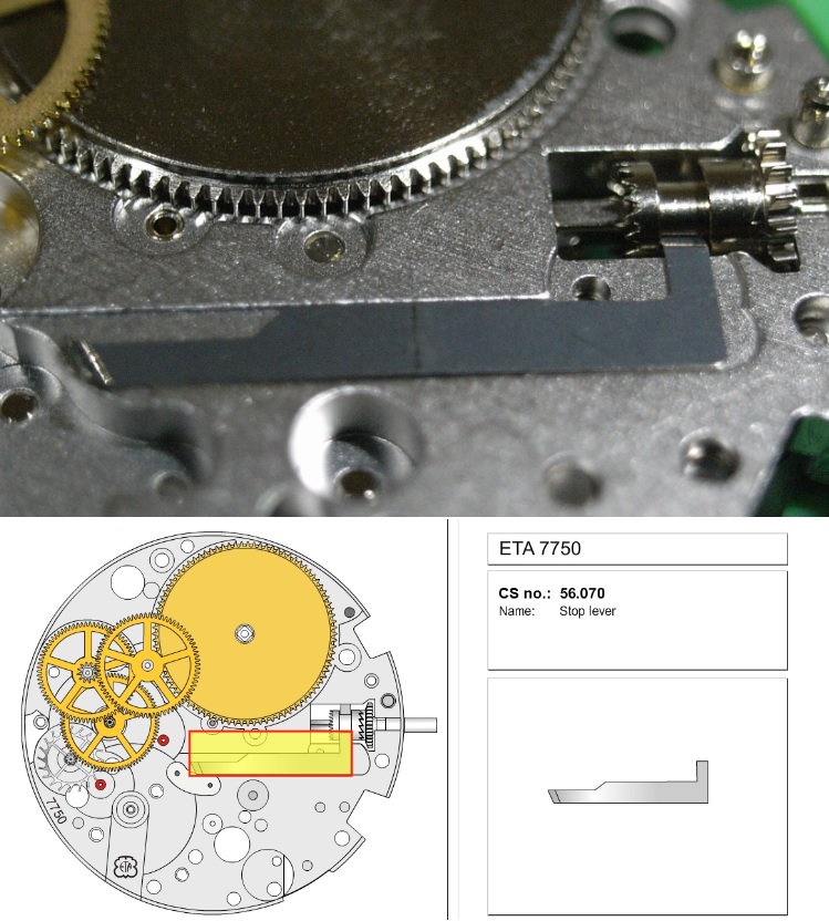
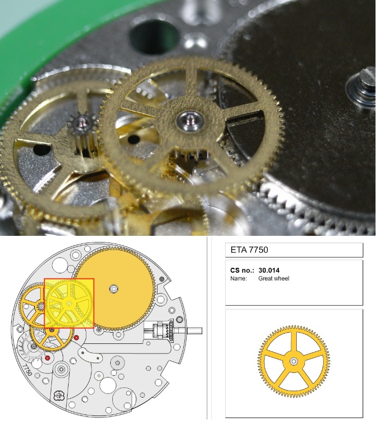
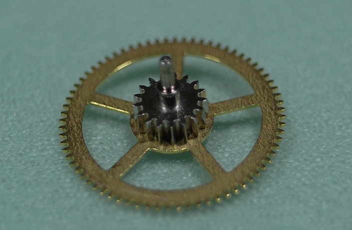
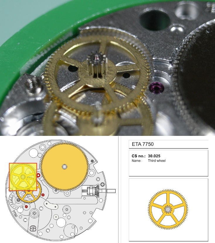
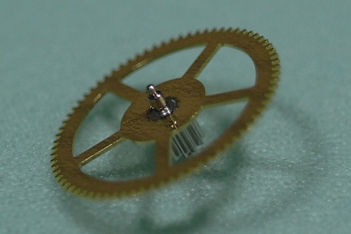
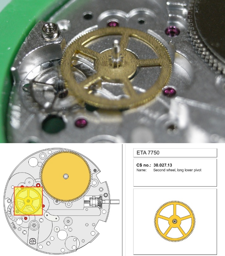
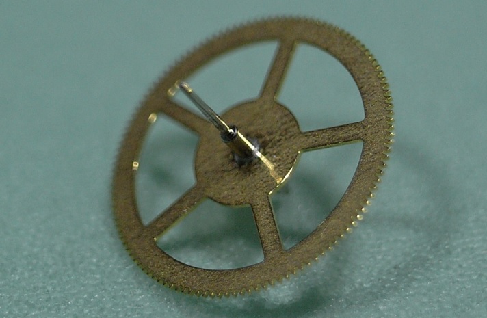
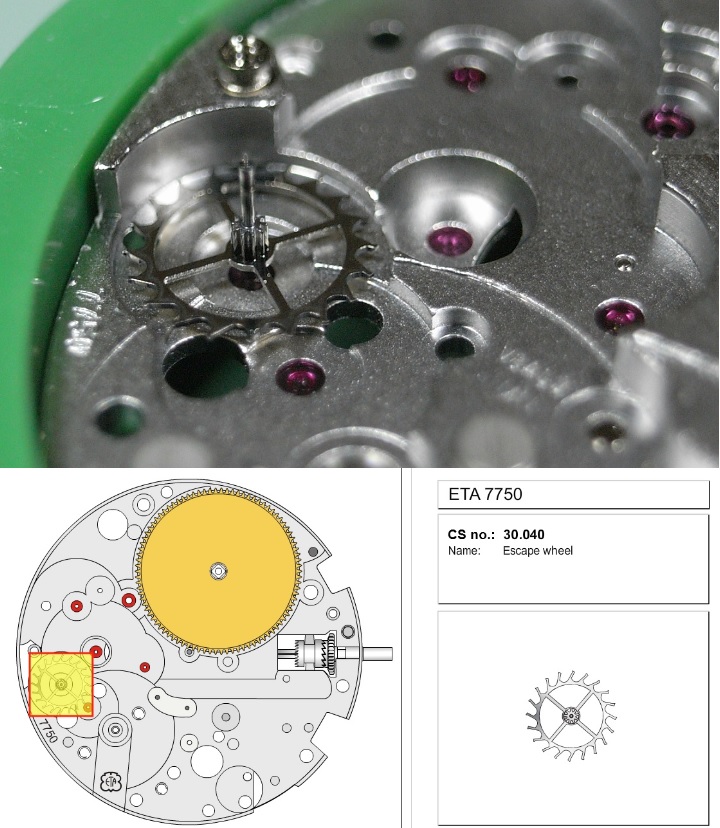
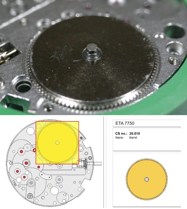
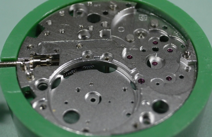
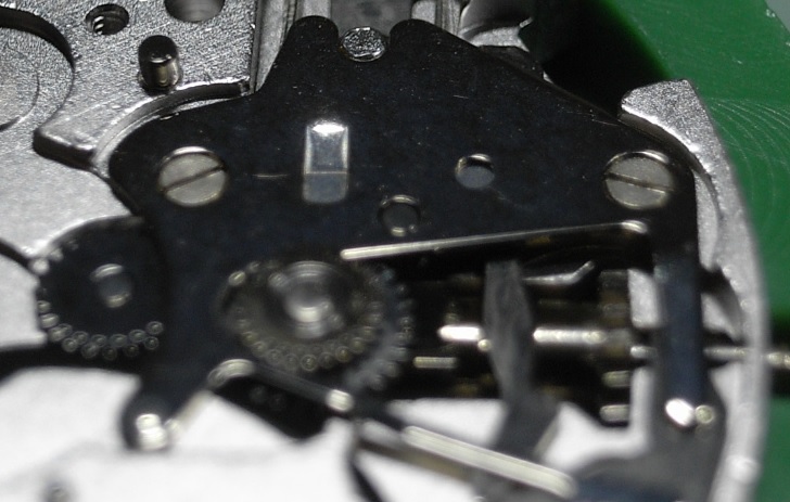
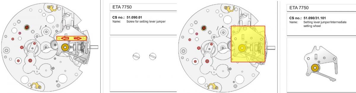
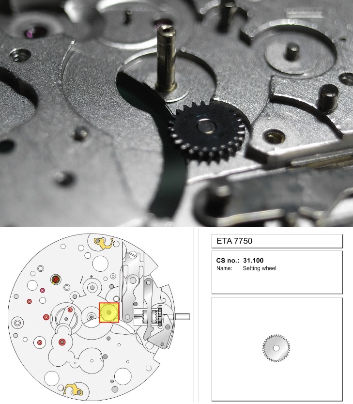
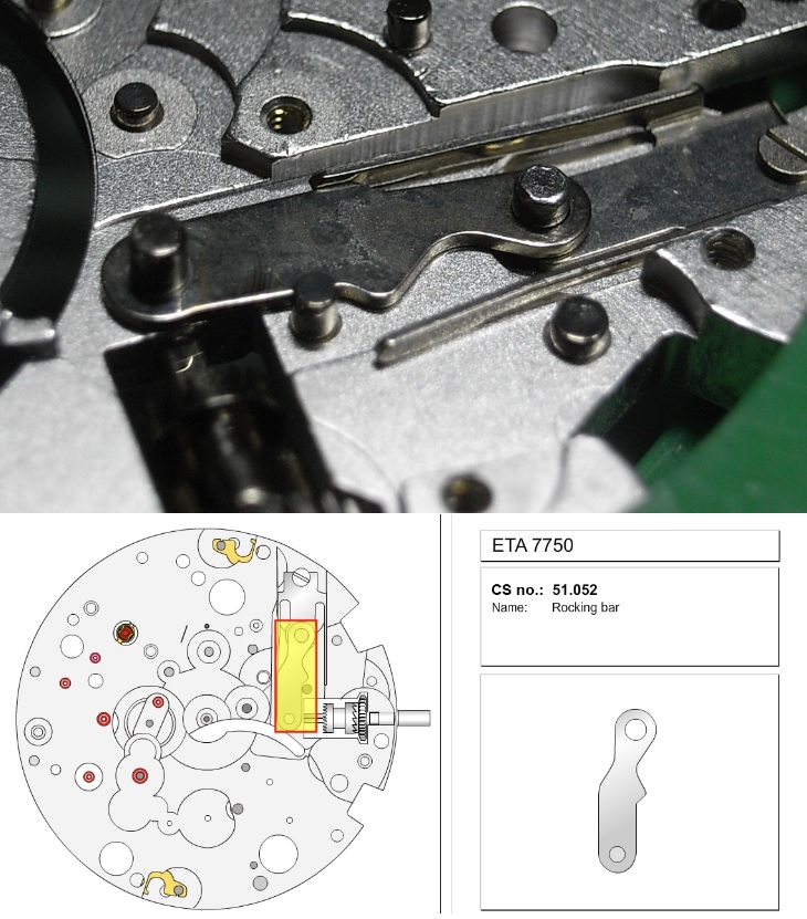
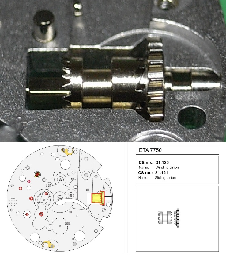
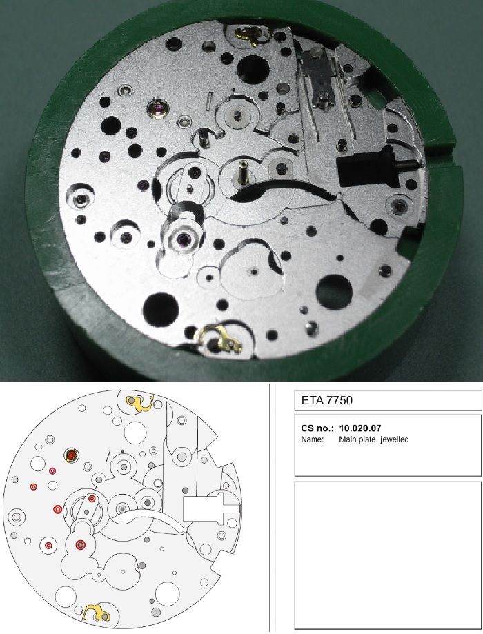
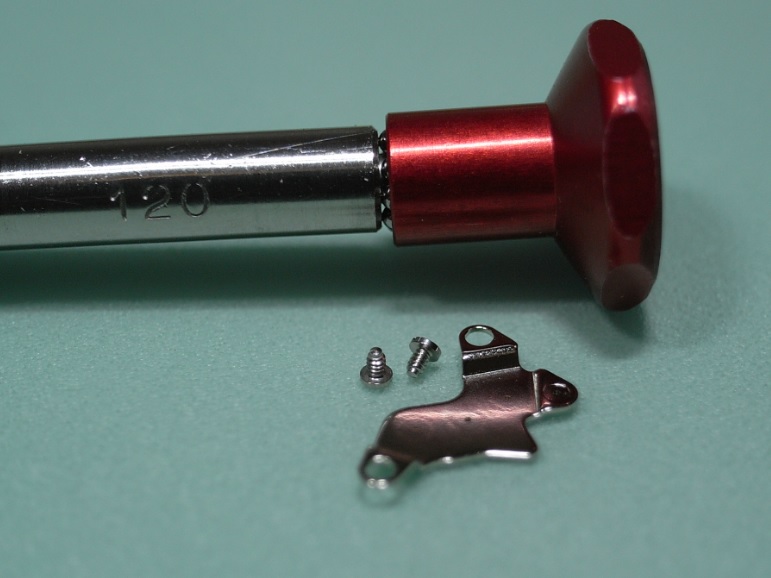
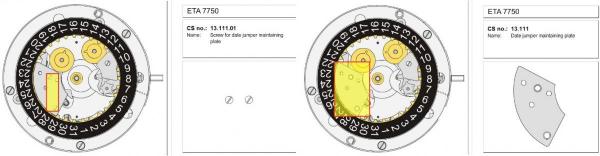
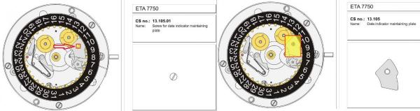
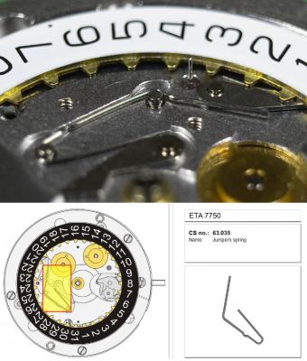
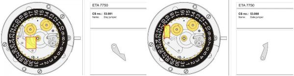
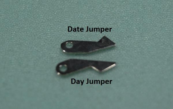
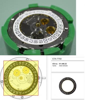
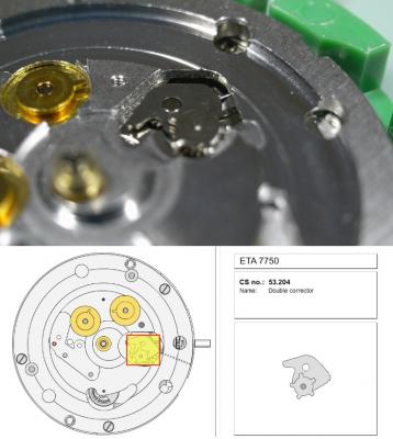
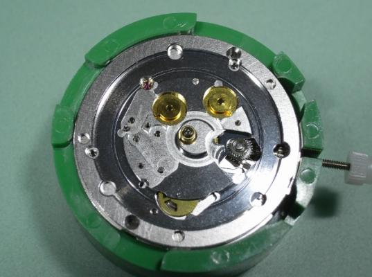
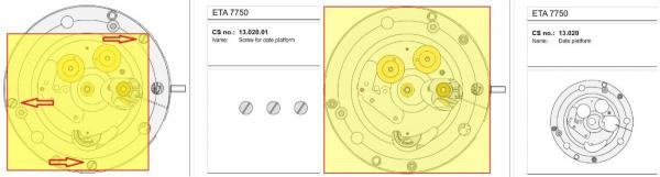
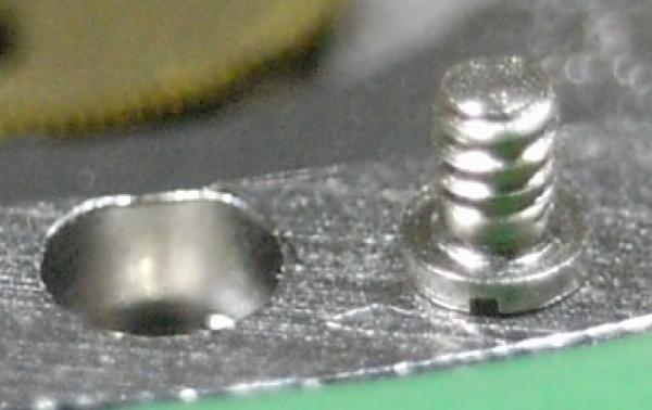
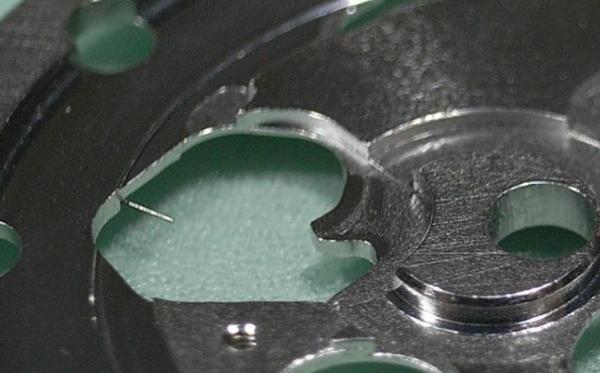
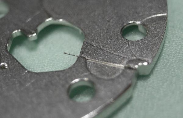
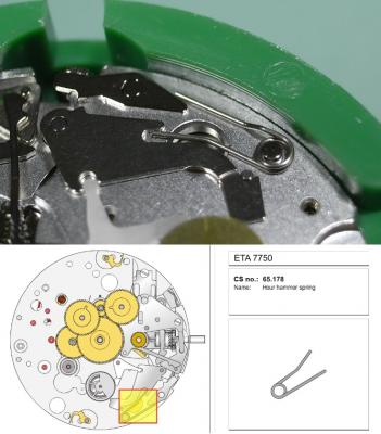
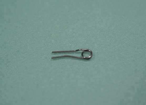
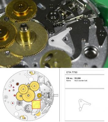
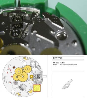
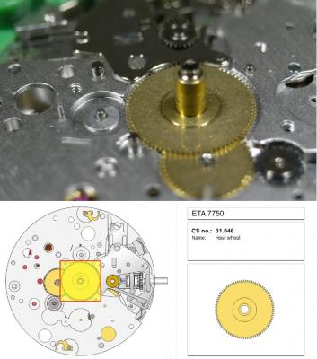
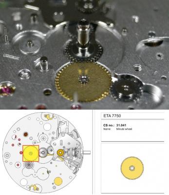
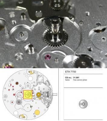
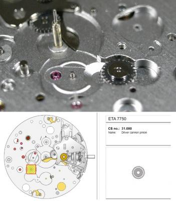
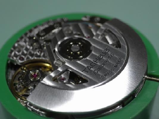
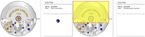
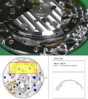
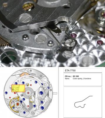
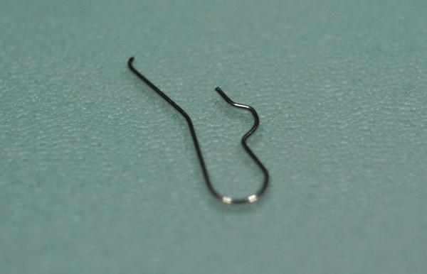
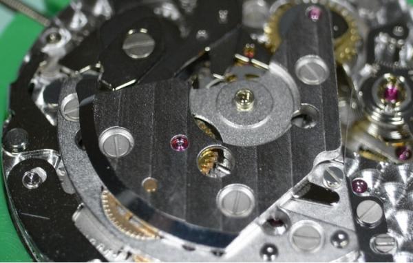
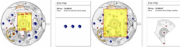
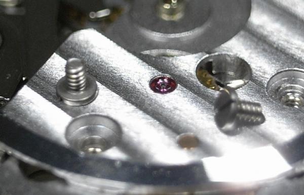
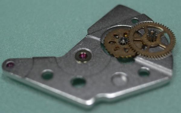
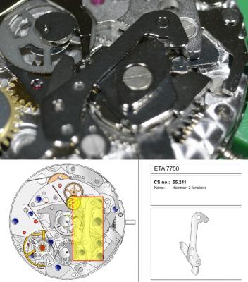
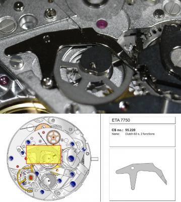
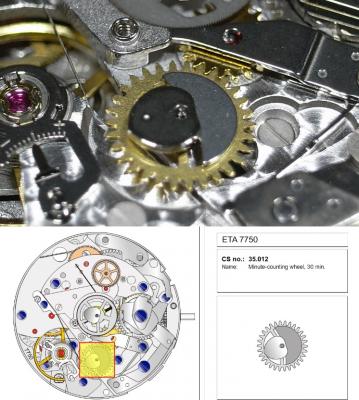
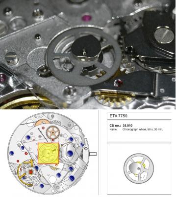
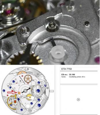
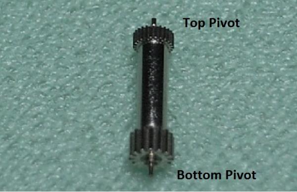
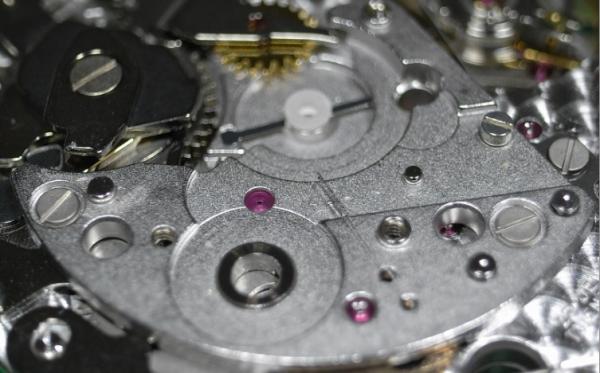
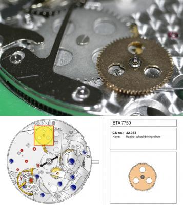
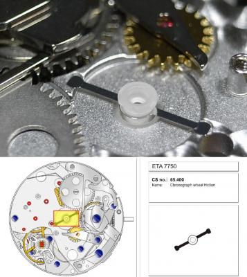
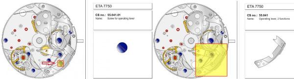
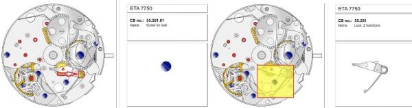
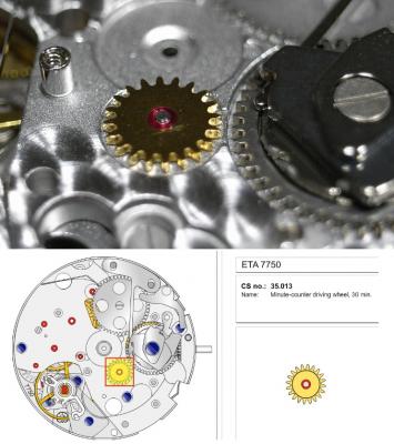
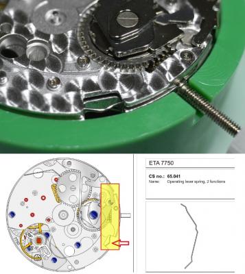
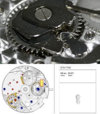
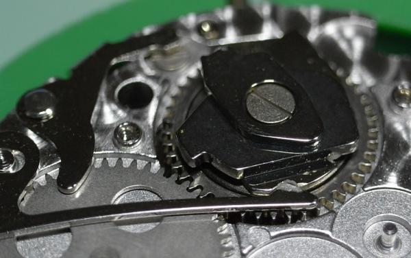
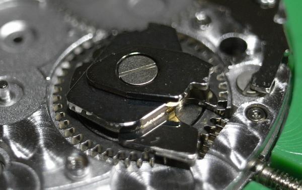
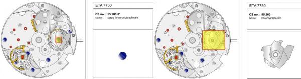
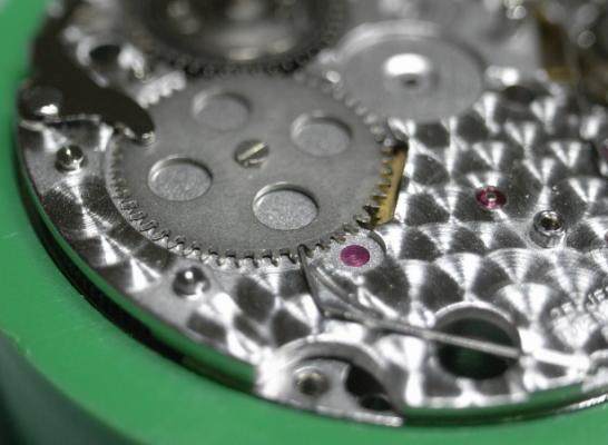
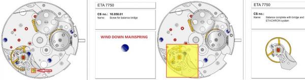
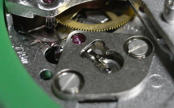
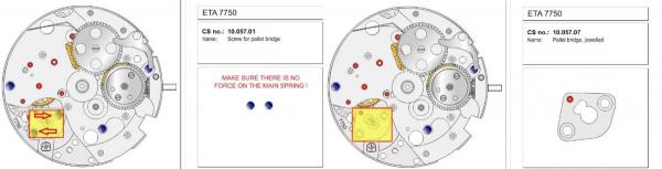
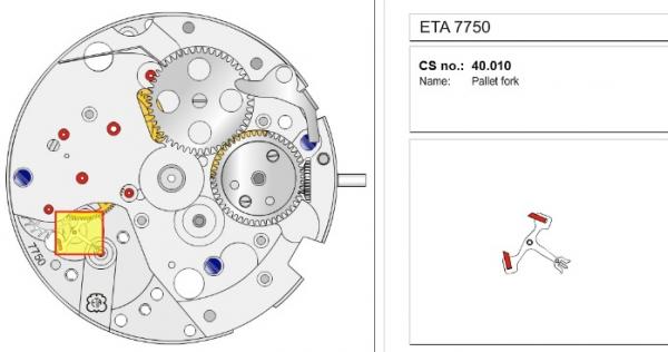
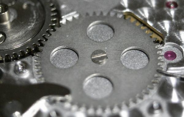
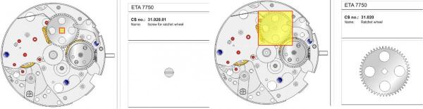
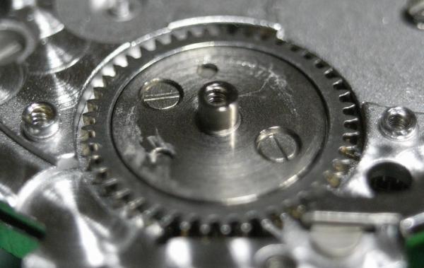
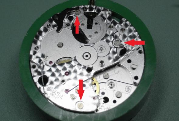
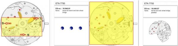
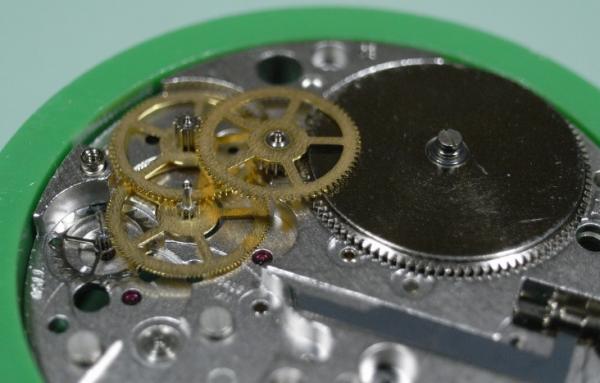
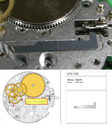
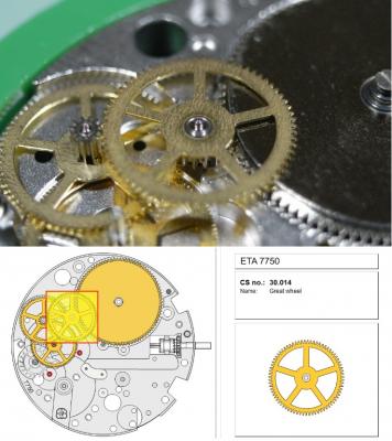
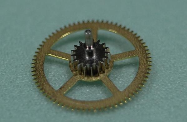
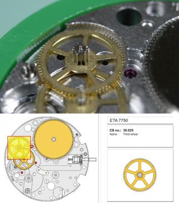
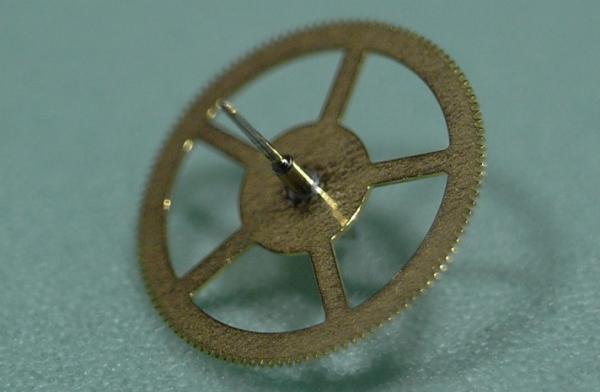
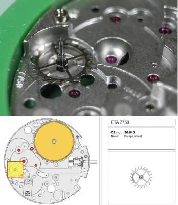
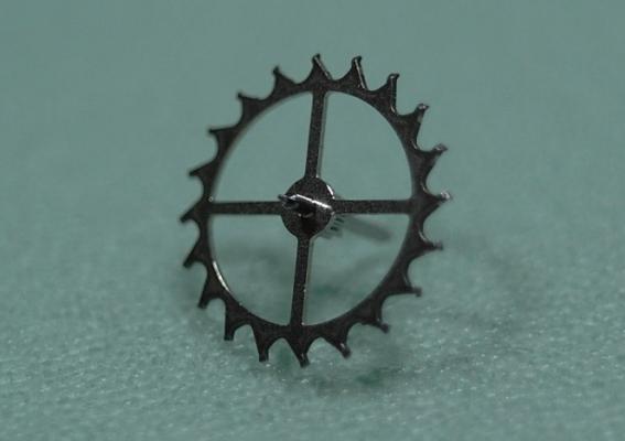
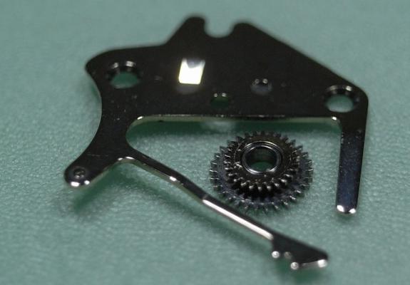
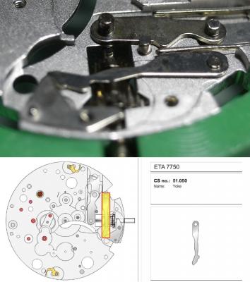
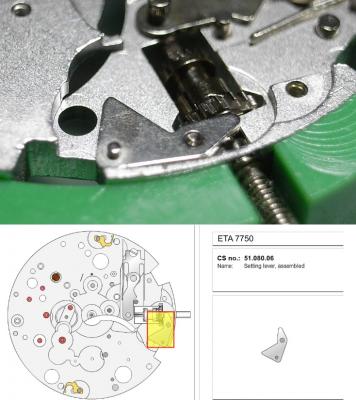
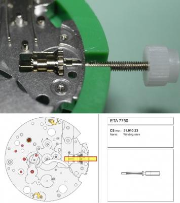
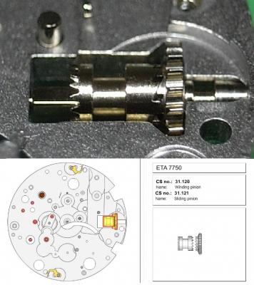
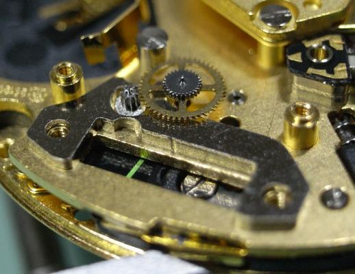
ETA 7750 Service Walkthrough The 7750 was first available in 1974, having been one of the first movements to be designed with the aid of a computer. It's hard to believe that the 7750 is still the industry standard movement for chronographs considering it's history. It was developed over 40 years ago by Valjoux, who was then a legendary movement maker that was part of the giant ASUAG conglomerate. But by the end of 1975 production was stopped due to the onslaught of the Quartz Era, and the 7750, along with many other mechanical calibers, was abandoned. Industry demand for this movement was so low that the stock produced in that 1 year manufacturing lasted until 1982! Such was the devastation of cheap Japanese produced quartz watches to Swiss manufactures. History may have forgotten the 7750 except for the local management at Zenith who ignored the orders by Valjoux to destroy the dies and equipment used to manufacture the 7750, instead hiding the equipment away from corporate eyes. You can find many more fascinating facts about this caliber online, and it's well worth the read. ................................................... This walkthrough will be very detailed, and I hope this will give people the courage to tackle this movement. I've serviced quite a few calibers, and this is one of the most beautiful, with a very logical layout. ETA7750 Tech.PDF If you have built your skills with basic movements, and become proficient in servicing them, I would highly recommend this movement to be your first chronograph to tackle. Lets begin. DEMAGNETIZE THE MOVEMENT BEFORE DISASSEMBLY. Remove the Day Indicator and store it in a safe place where it won't be damaged. Unscrew (0.8 Driver) the Jumper Maintaining Plate and remove it. Do the same for the Date Indicator Maintaining Plate Carefully remove the Jumpers Spring, holding it with a piece of pegwood so it doesn't ping away. Next remove the jumpers for the day and date. The jumpers differ from one another, so here is a reference photo so you can see the difference. Remove the Date Indicator and place it in a safe place where it won't be damaged. The last piece to remove on the Date Platform is the Double Corrector Now unscrew (1.4 Driver) the Date Platform and gentle pry it from the movement. Be careful when removing this plate, as there is a fine spring pressed into the plate that can be easily damaged. Here is a reference photo of the screws that hold the Date Platform. Remove the Hour Hammer Spring, once again using the pegwood to hold the spring while removing the tension. Here is a reference photo of the correct orientation of the spring. Remove the Hour Counter Lock. Remove the Hour Hammer Operating Lever. Next is the Hour Hammer, be careful when removing this item so as not to damage the Hour-Counting Wheel. Now remove the Hour-Counting Wheel. Remove the Date Indicator Driving Wheel Remove the Day Star Driving Wheel Then remove the Intermediate Calendar Driving Wheel Remove the Hour Wheel Then the Minute Wheel Remove the Cannon Pinion, which does not require a puller. The last component to be removed on this side of the Main Plate is the Driver Cannon Pinion. To lift the Driver Cannon Pinion I used what Mark used, a set of hand lifter from Horotec (MSA05.007); but you can also use a Presto Tool (30636-1) which will also work well. The dial side of the movement is now complete disassembled. Flip the movement over and unscrew (1.5 Driver) the Oscillating Weight. To remove the Hammer Spring lift it up gently over the automatic work and move it inwards. This will move the tail of the spring in a clockwise motion to the opening in the slots, which will free the spring. Slide out the Clutch Spring. Here is a reference photo of this spring, and it's orientation. Remove the screws (1.4 Driver) for the Automatic Device Bridge, and gently pry it loose. Here is a reference photo of these screws for the bridge. Once the Automatic Bridge has been removed, the two wheels for the automatic work are able to be removed. Below is a reference photo of how the sit inside the bridge. We now begin to disassemble the chronograph section of this movement. Begin with removing the Hammer, 2 Functions. Next remove the Clutch 60s, 2 Functions. Then remove the Minute-counting Wheel, 30min. Remove the Chronograph Wheel 60s, 30min. Gently lift out the Oscillating Pinion, 60s. Here is a reference photo of the orientation of this pinion. Unscrew (1.4 Driver) the Chronograph Bridge and gently pry it off the Train Wheel Bridge. Remove the Ratchet Driving Wheel. Remove the Chronograph Wheel Fiction. Unscrew (1.4 Driver) the Operating Lever, 2 Functions. Unscrew (1.4 Driver) the Lock, 2 Functions. Next remove the Minute-counter Driving Wheel, 30min. Slide out the Operating Lever Spring, 2 Functions. This spring can be fitting in both directions; but only 1 way is correct. Here is a reference photo of it's correct orientation. Remove the Switch. Here I digress from the order the SwissLab document illustrates the order of removal. They show to remove the Chronograph Cam before removing the Hammer Cam Jumper. This in my opinion is not the best way, as all the force from the jumper is pressing on the cam whilst your trying to remove it, and could lead to damage. Instead I move the Chronograph Cam until it reaches the notch as shown in the photo below. Then lift the Hammer Cam Jumper up to the top of the Chronograph Cam, which will release it's tension. Then, just as you removed the previous hammer, rotate the jumper to the opening in the slots, which will free the spring. Now you can unscrew (1.4 Driver) and remove the Chronograph Cam safely without tension on it. RELEASE THE MAINSPRING TENSION Once the tension has been released, unscrew (1.4 Driver) and remove the Balance Cock. Then unscrew (1.4 Driver) the Pallet Bridge and remove the bridge and Pallets. Unscrew (1.2 Driver) and remove the Ratchet Wheel. Then remove the Crown Wheel. Unscrew (1.4 Driver) the Train Wheel Bridge and gently pry it off the Main Plate. Note that one of the screws is under the Operating Lever. This needs to be moved out of the way to access this screw. The last level of this movement contains the train. Here is a reference photo of the wheel locations. Remove the Stop Lever. Remove the Great Wheel. Here is a reference photo of the underneath of this wheel. Remove the Third Wheel. Here is a reference photo of the underneath of this wheel. Remove the Second Wheel. Here is a reference photo of the underneath of this wheel. Note this has the long lower pivot. Remove the Escape Wheel. Here is a reference photo of the underneath of this wheel. Then remove the Barrel. This completes the removal of the train. Flip the movement over so we can complete the disassembly by removing the keyless work. Firstly, release the tension from the Setting Lever Jumper. Then unscrew (1.2 Driver) and remove the Setting Lever Jumper. These are unique screws with pointed ends, and below is a reference photo of them. This will also remove the Intermediate Setting Wheel. Next remove the Setting Wheel Then remove the Yoke. Remove the Setting Lever. Remove the Rocking Bar. Now pull out the Stem. Once the Stem is removed the Winding and Sliding Pinion should fall out of the movement onto your work mat. Disassembly of the 7750 is now complete If you've come this far, congratulation on completing the disassembly. Make sure you pegwood all the jewels and reinstall the Balance back onto the movement for cleaning. Assembly of the movement will be posted as soon as I complete the write-up.


 1 point
 -
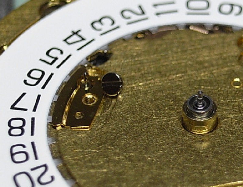
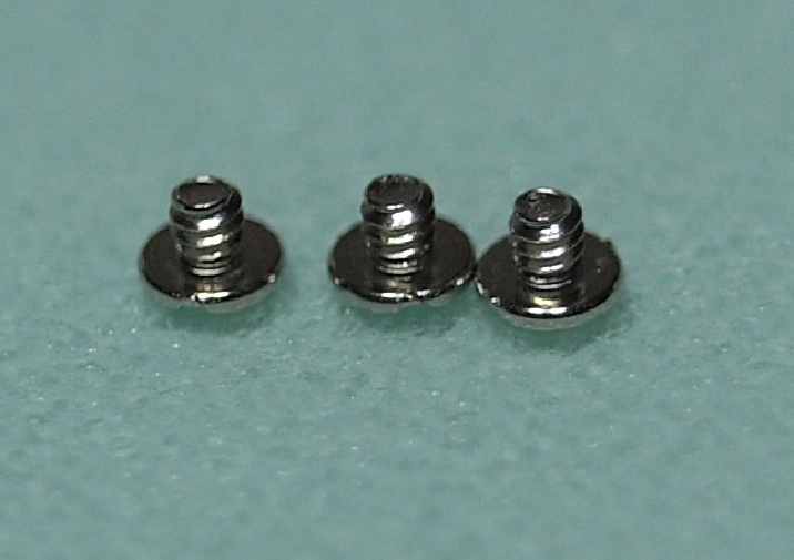
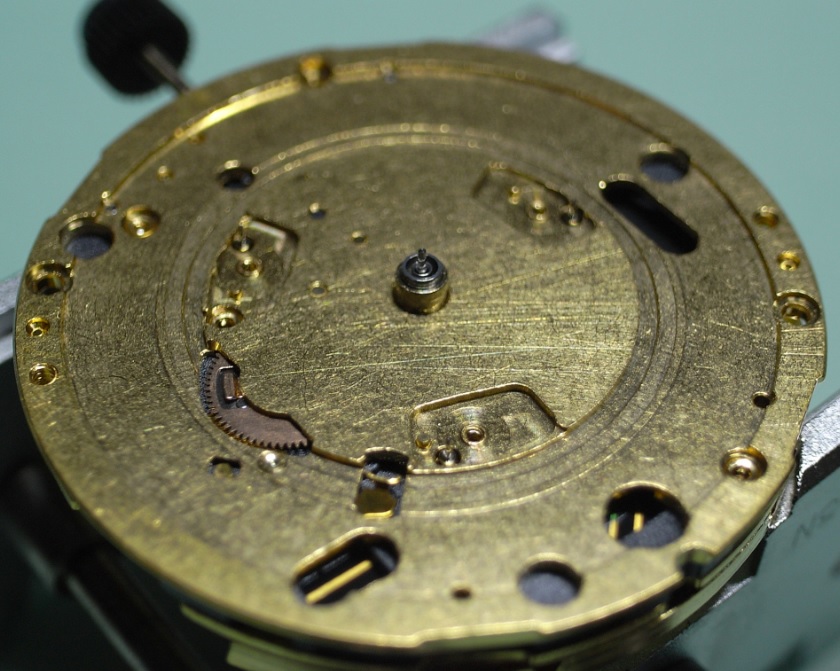
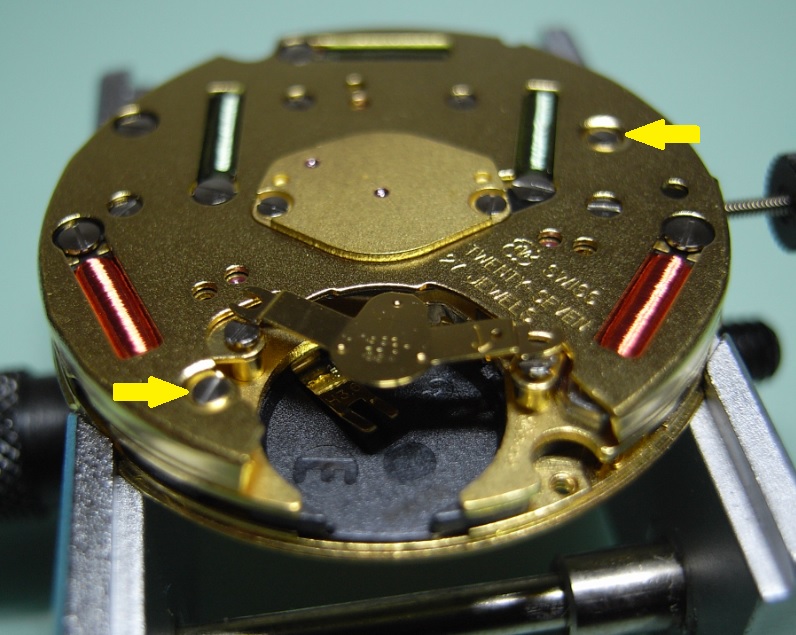
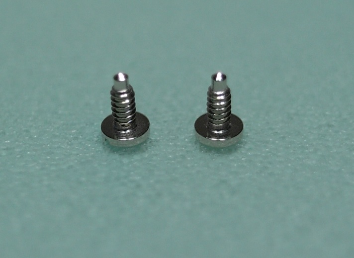
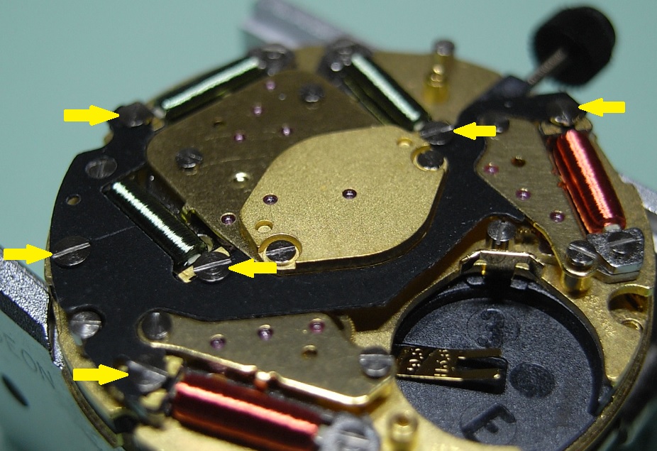
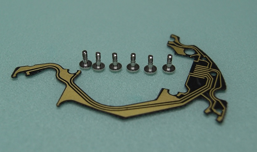
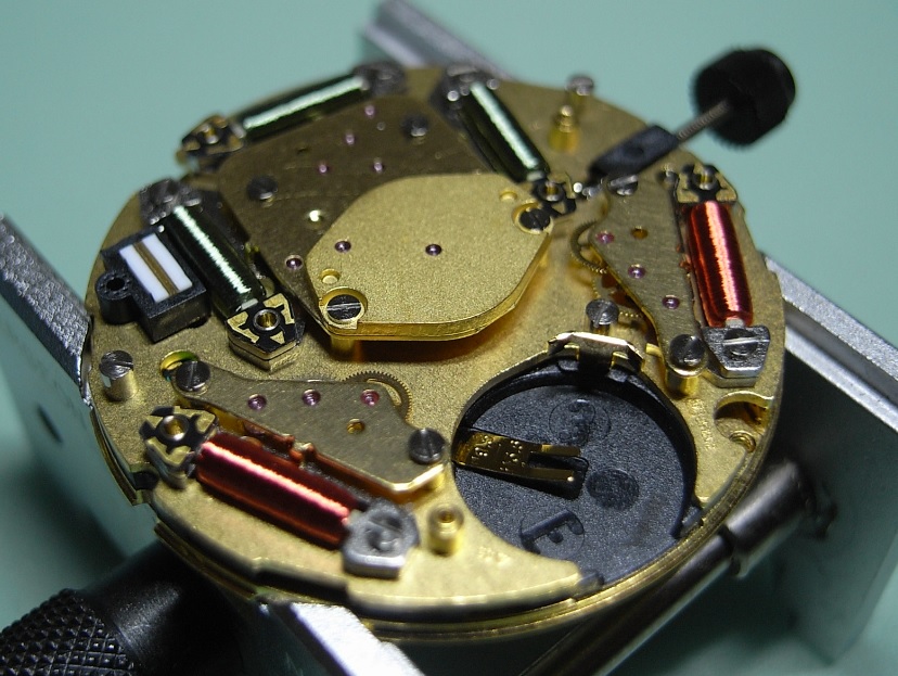
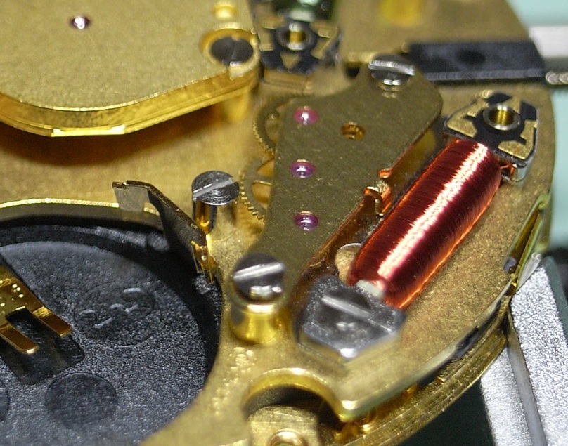
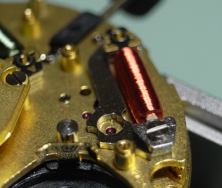
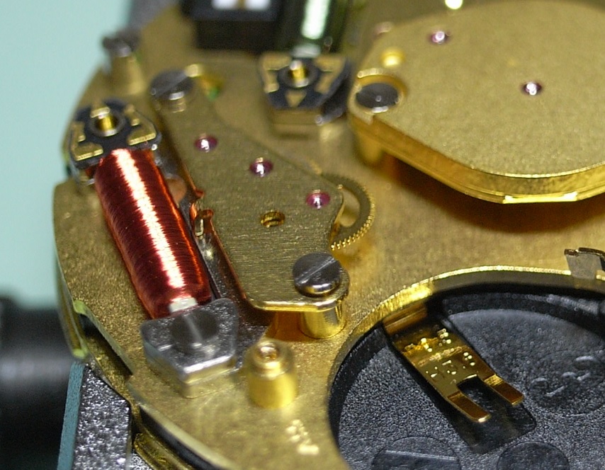
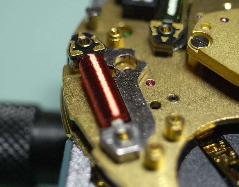
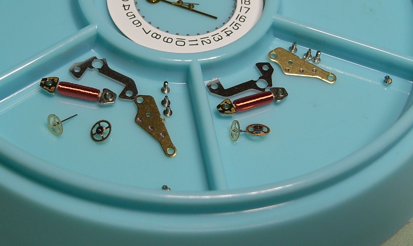
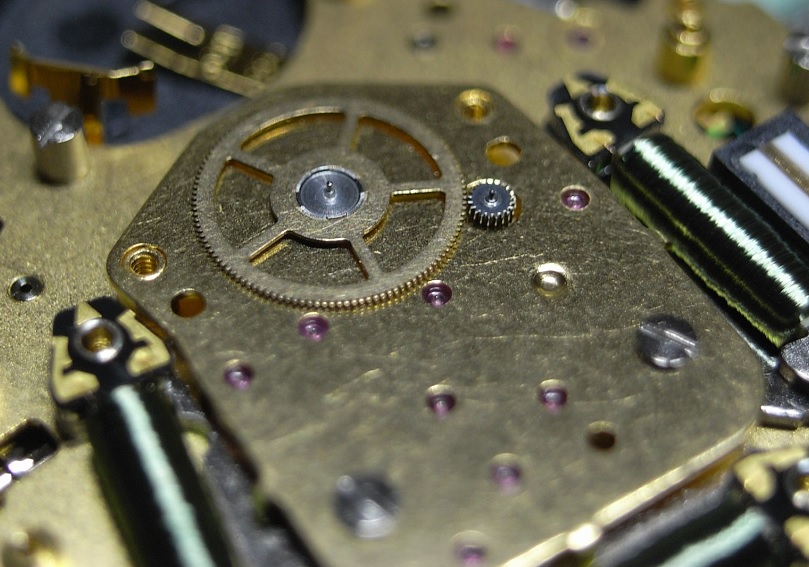
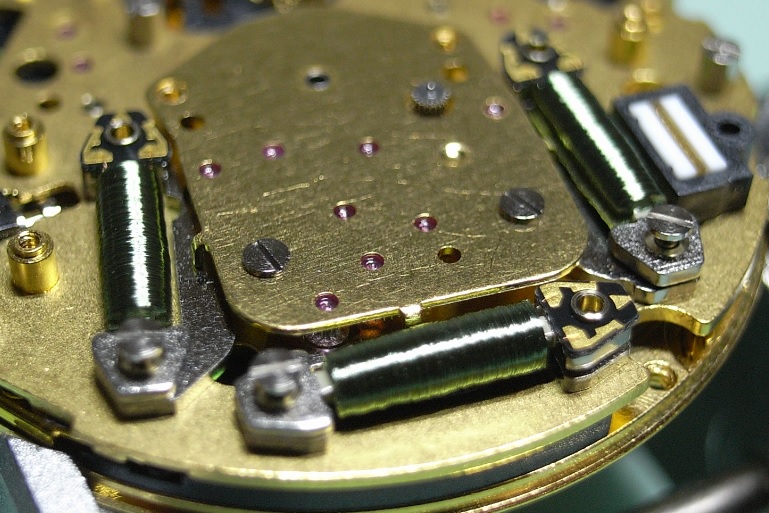
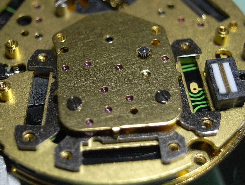
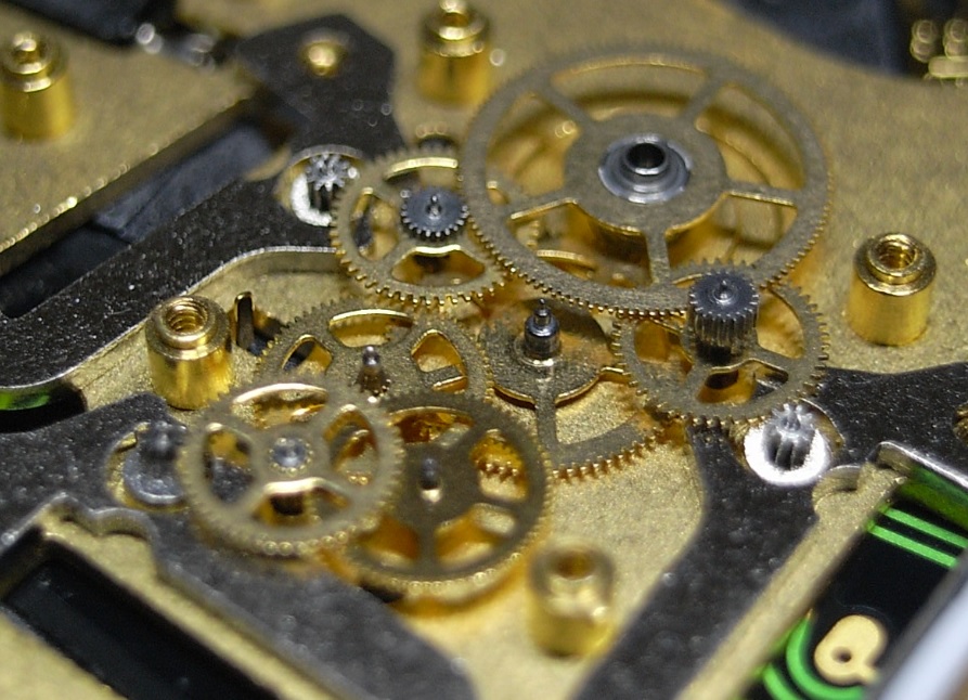
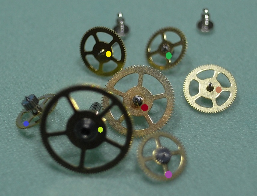
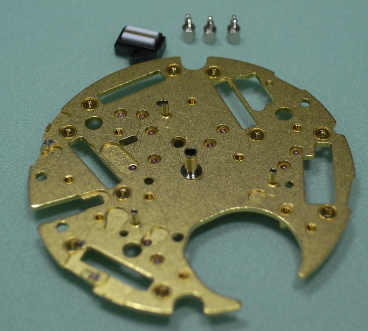
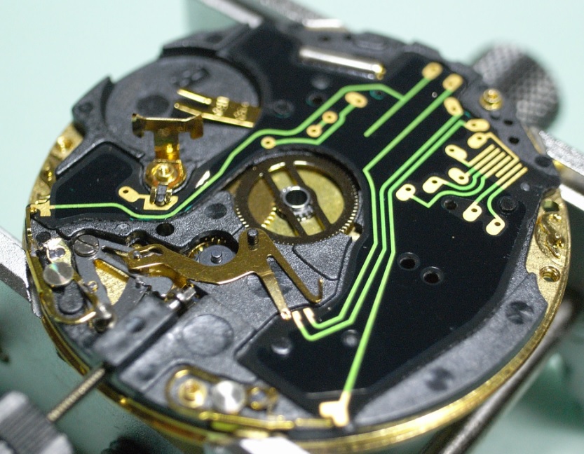
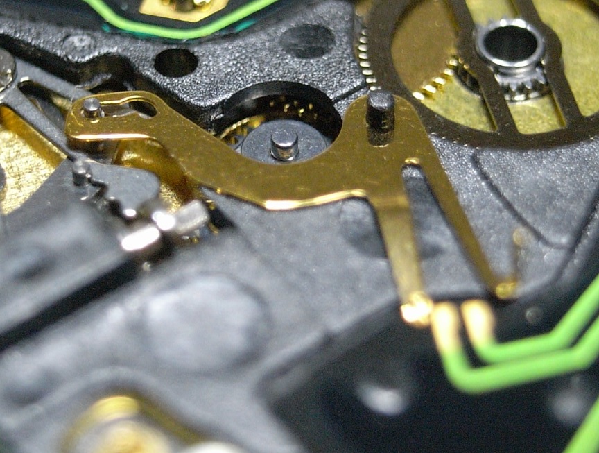
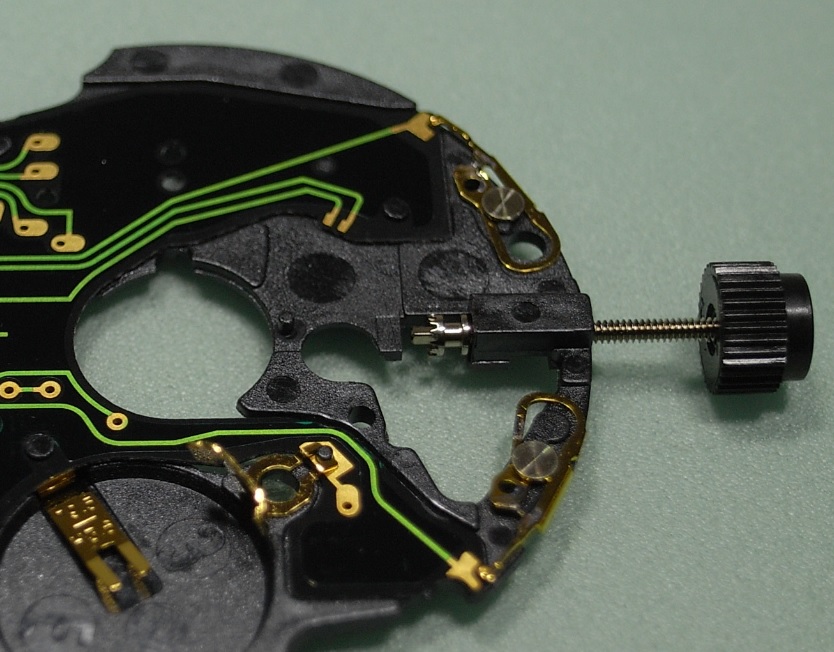
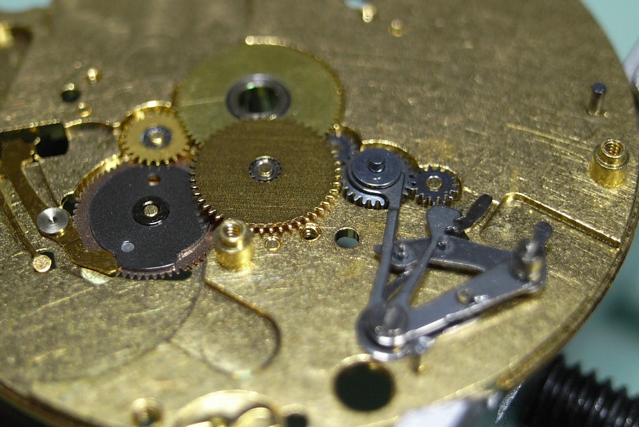
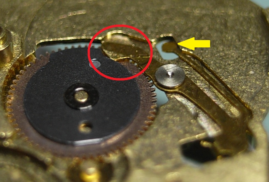
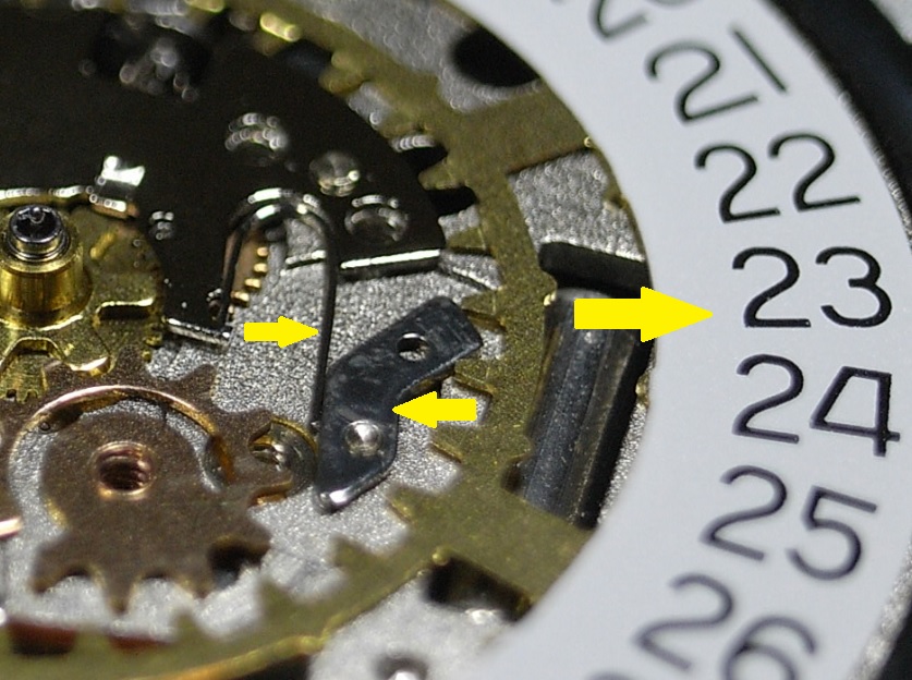
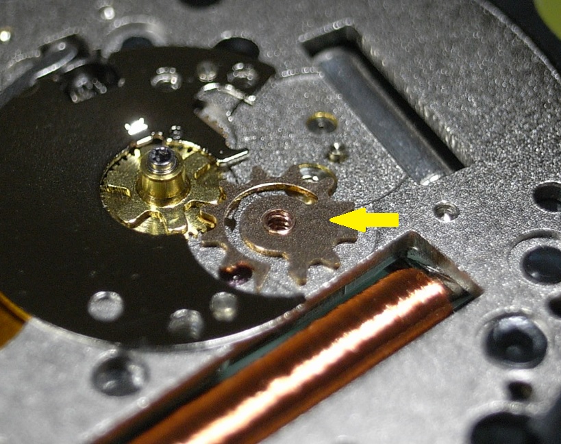
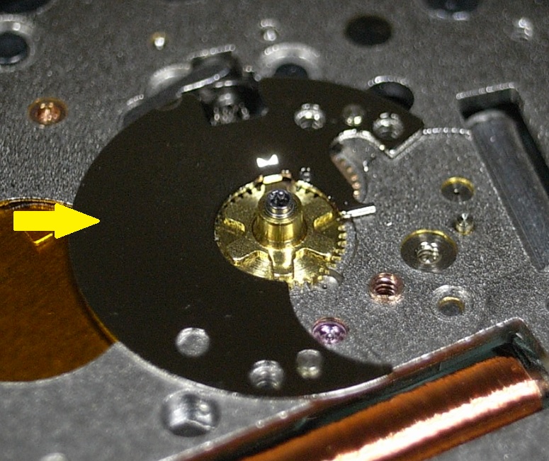
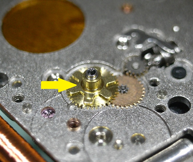
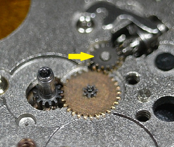
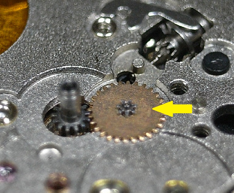
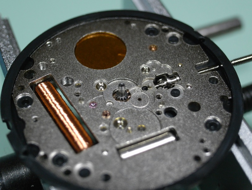
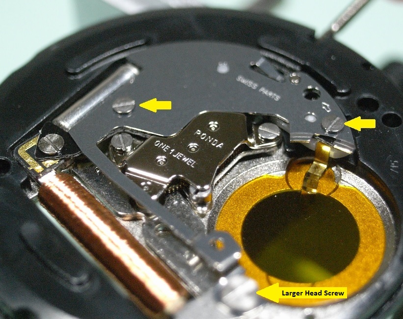
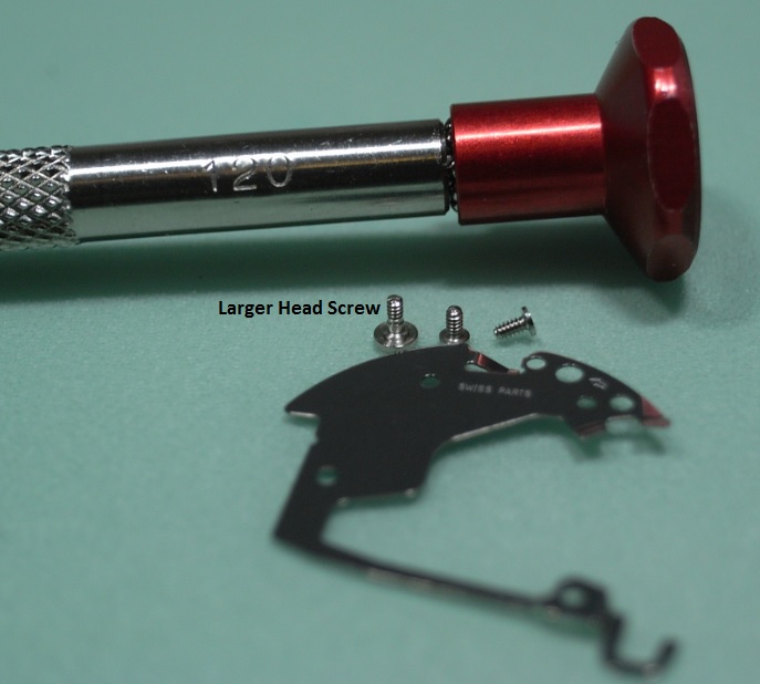
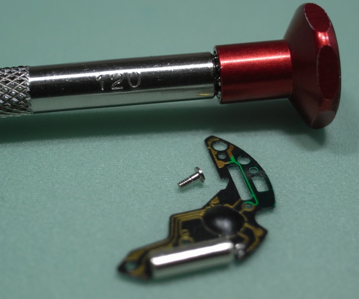
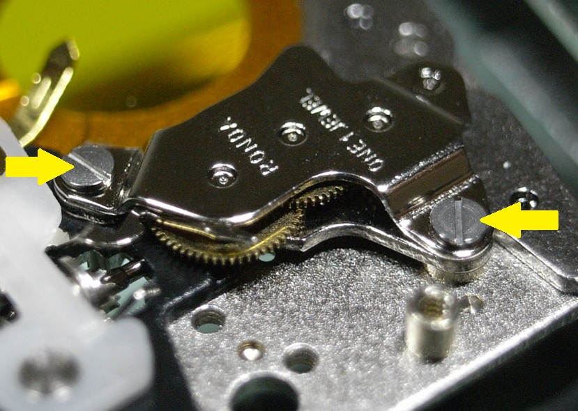
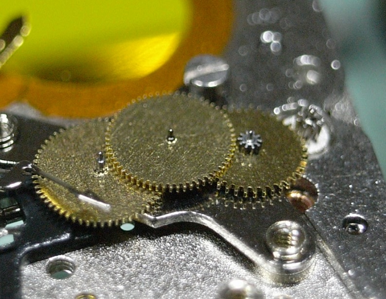
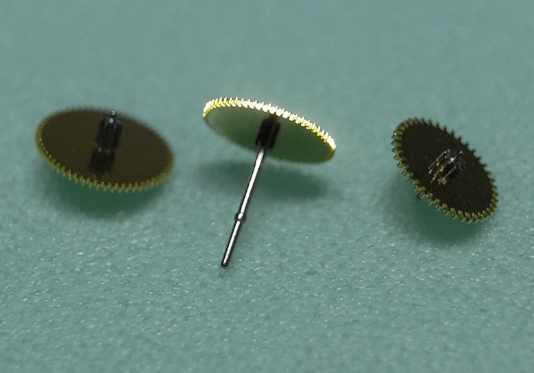
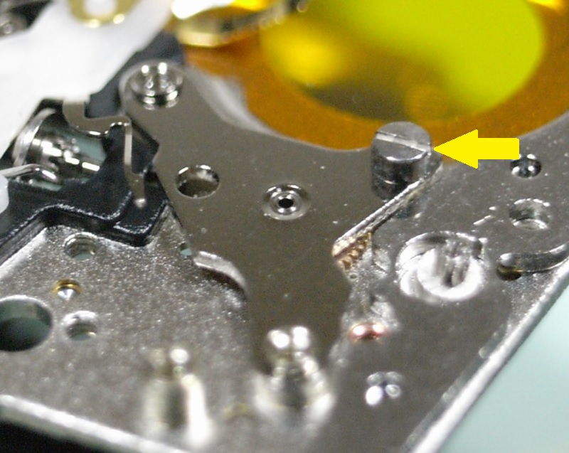
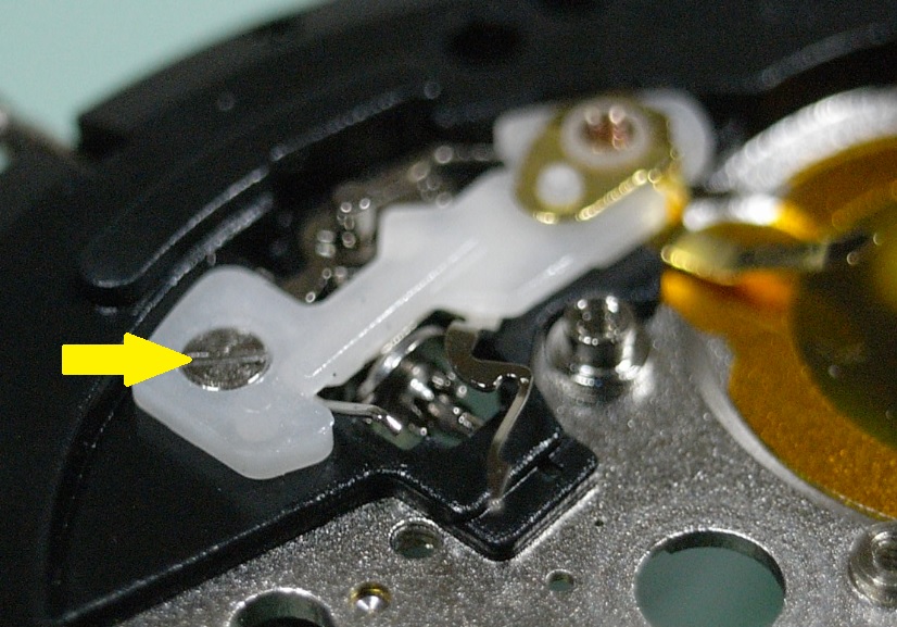
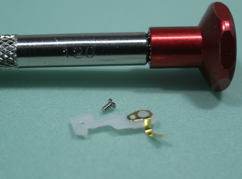
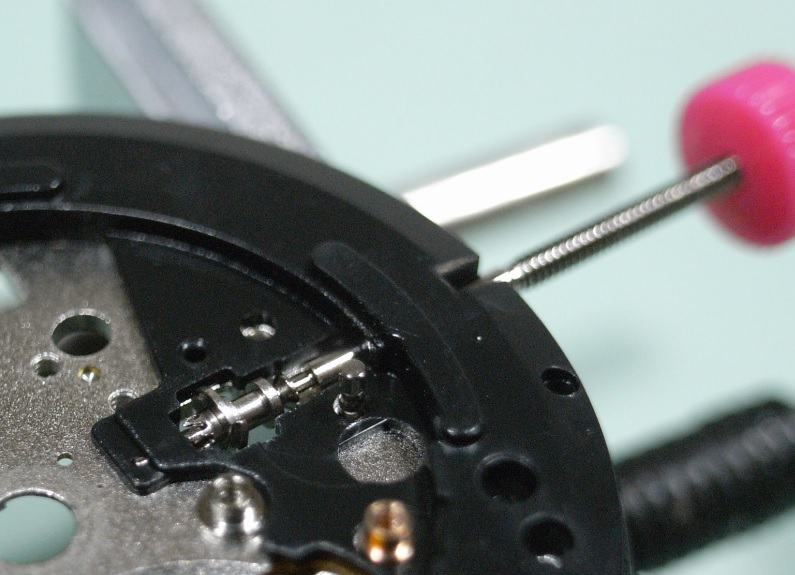
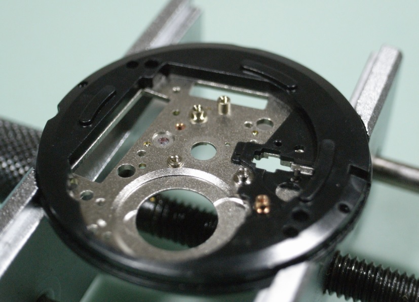
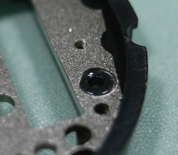
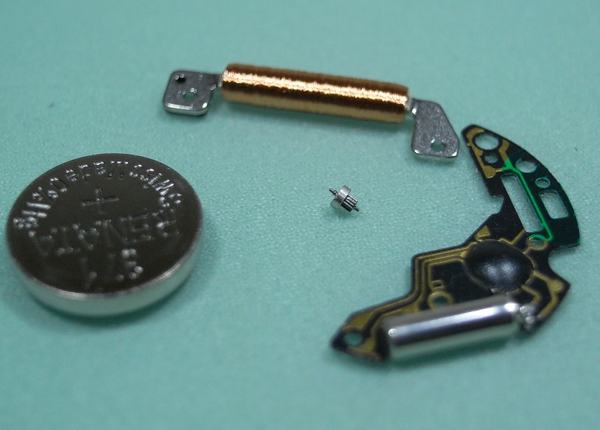
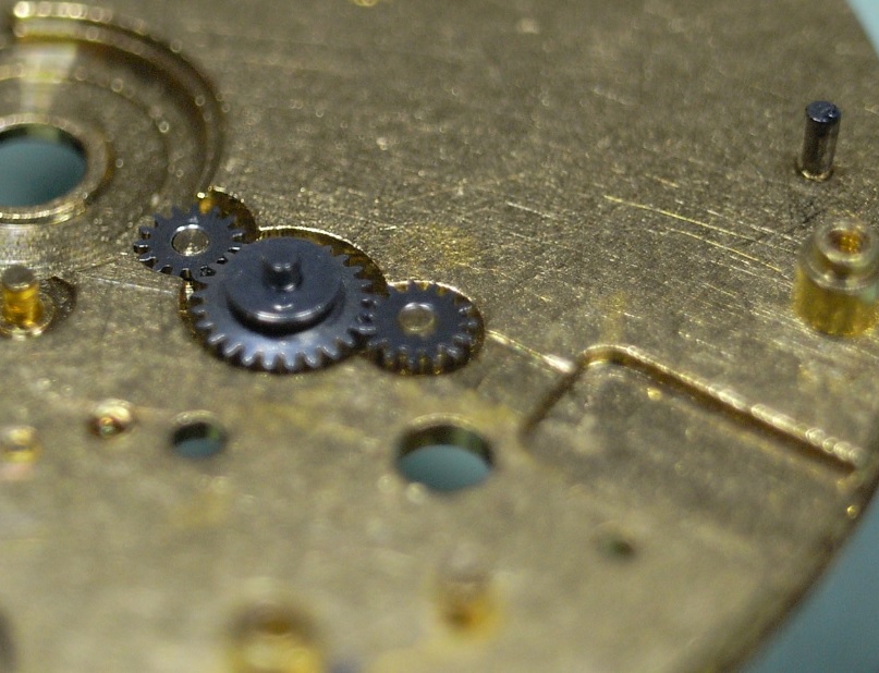
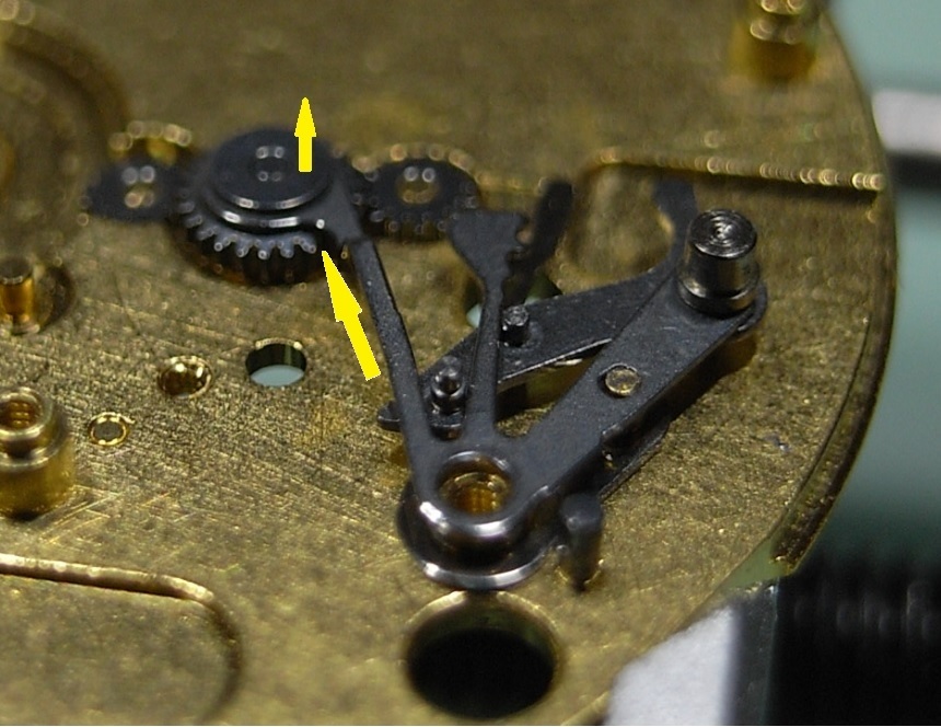
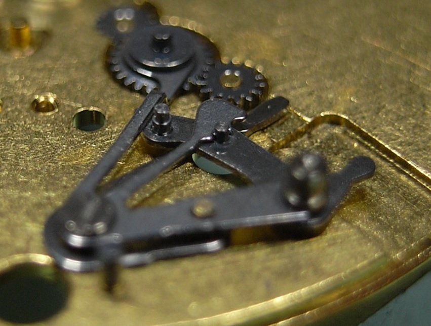
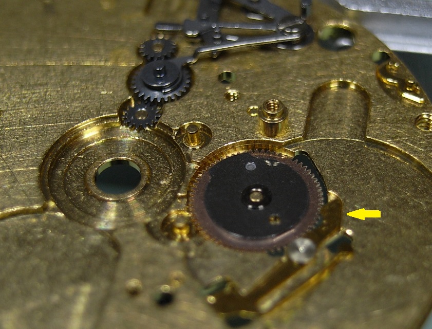
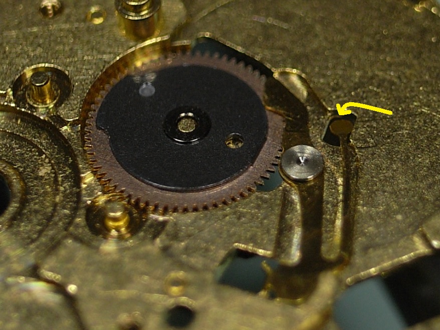
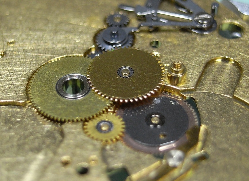
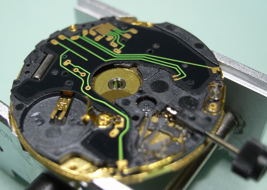
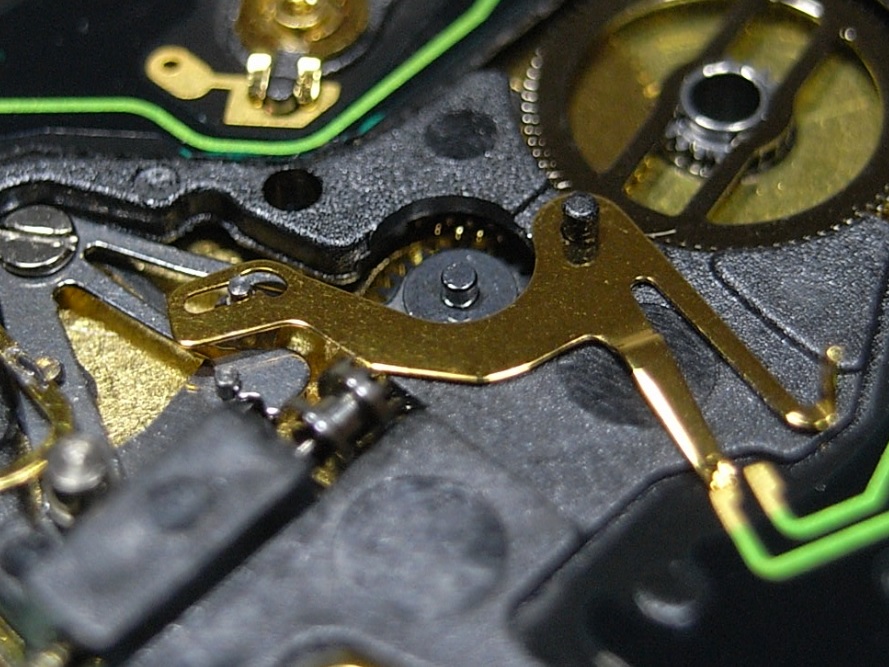
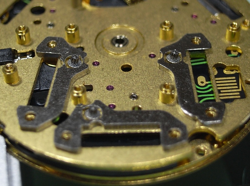
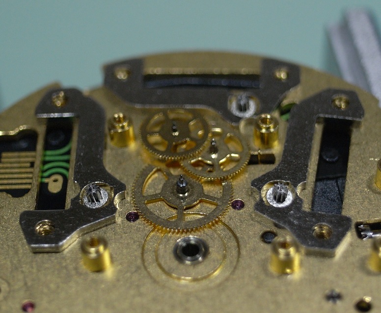
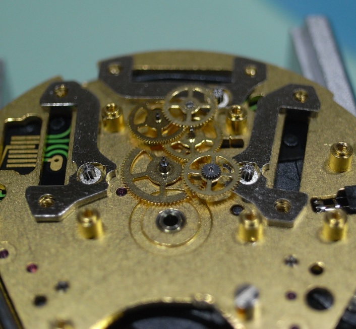
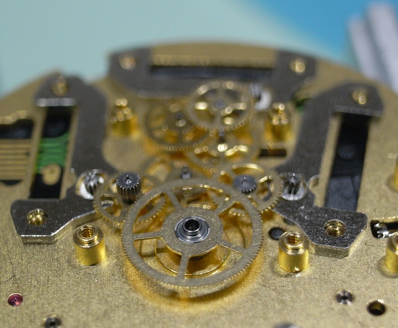
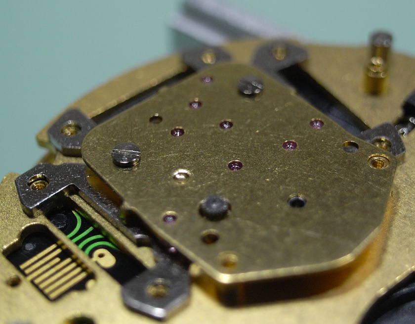
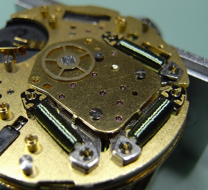
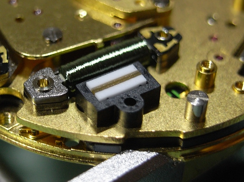
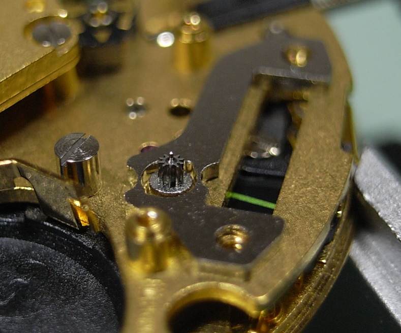
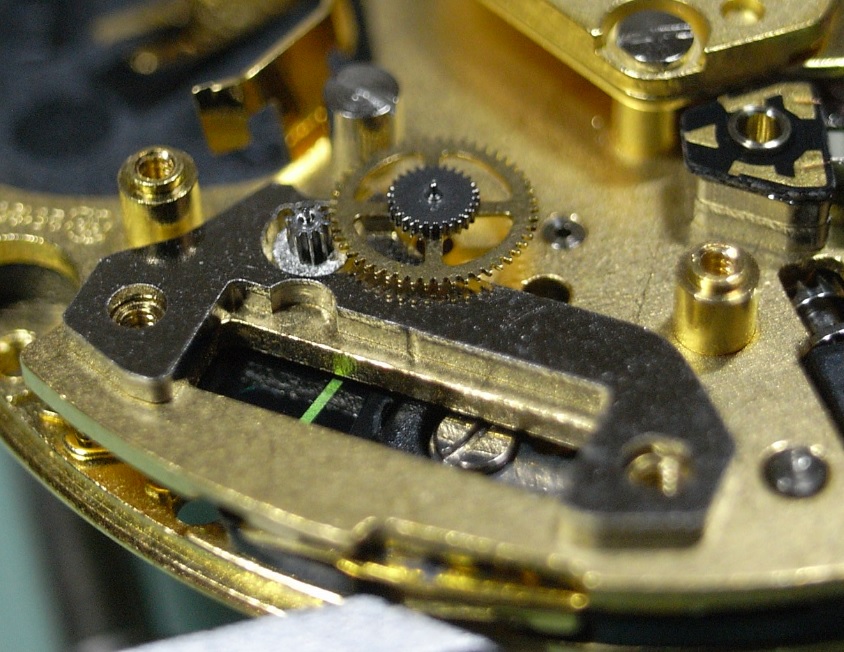
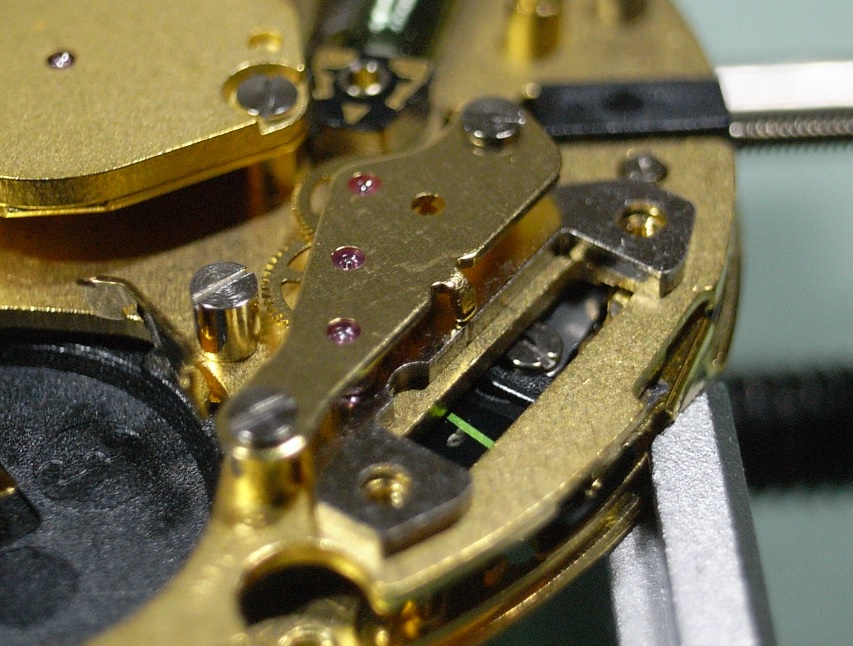
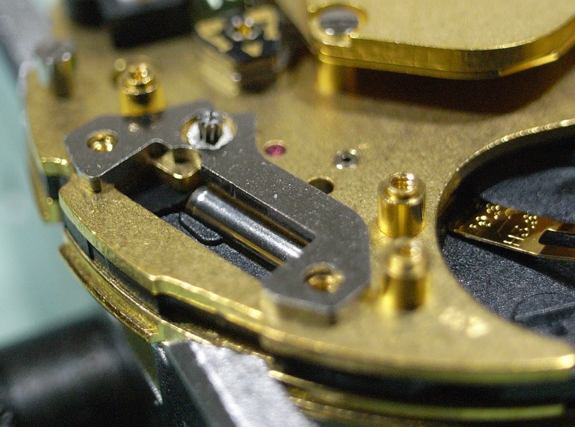
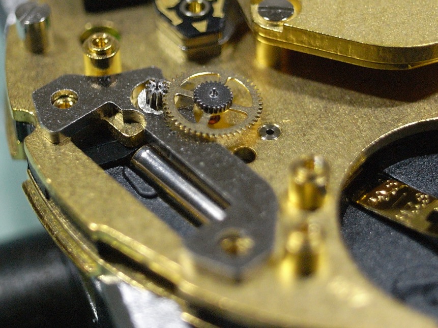
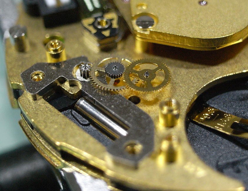
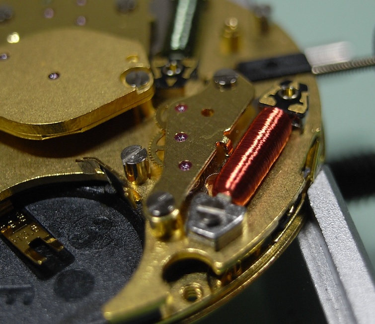
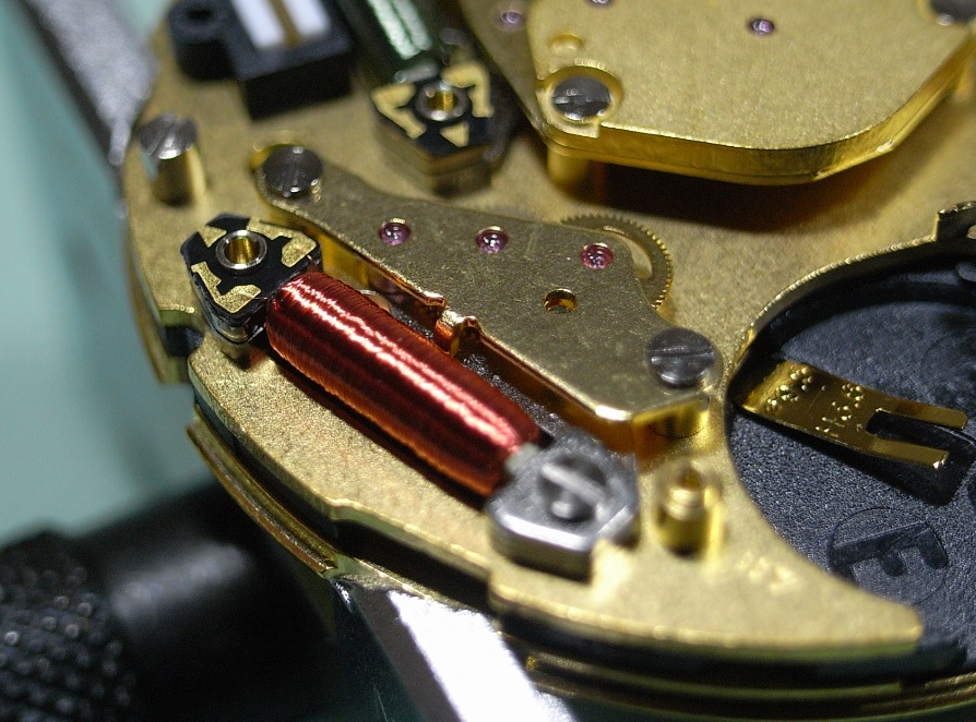
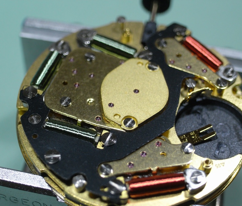
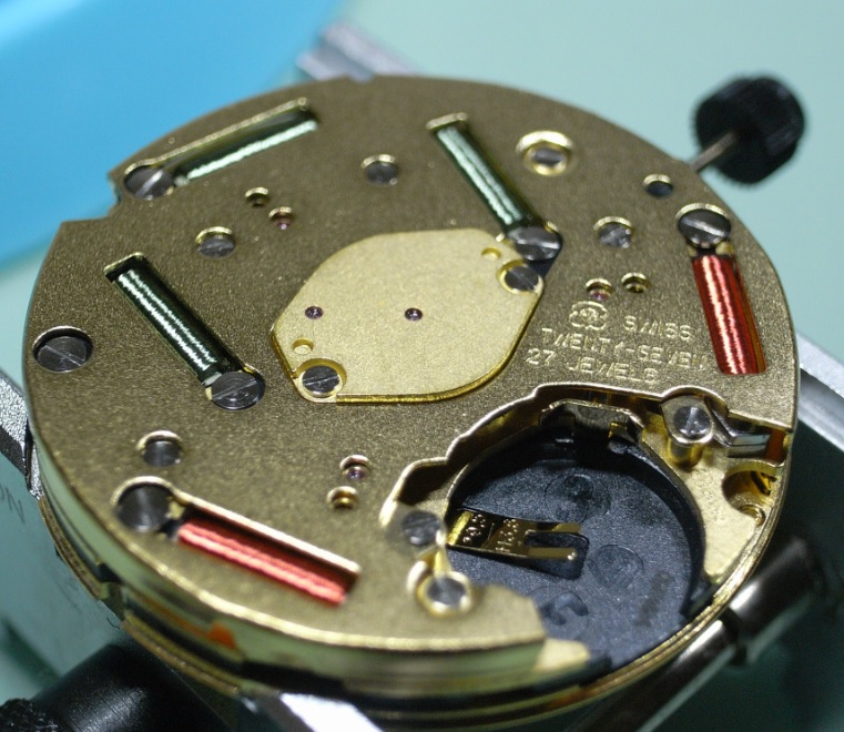
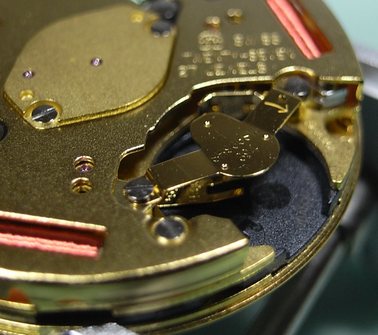
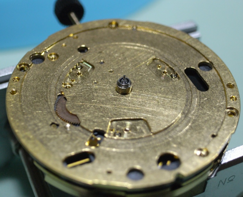
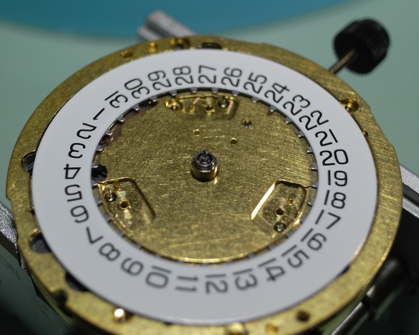
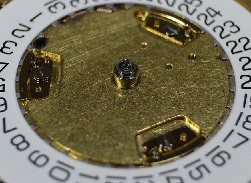
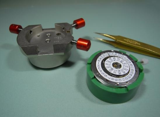
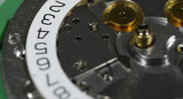
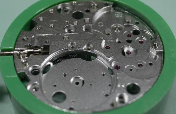
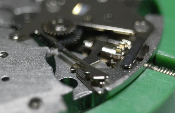
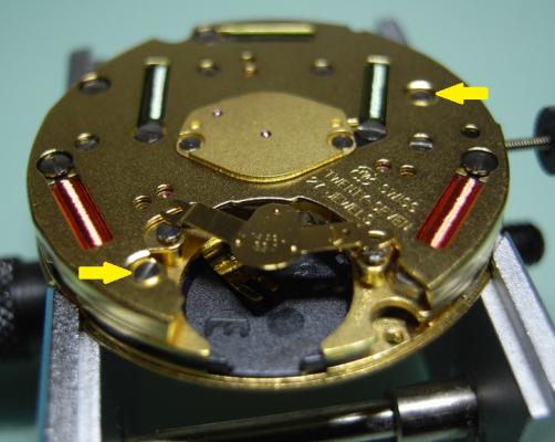
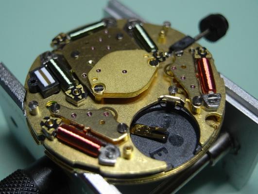
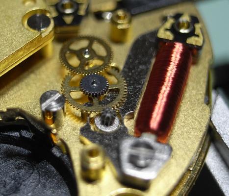
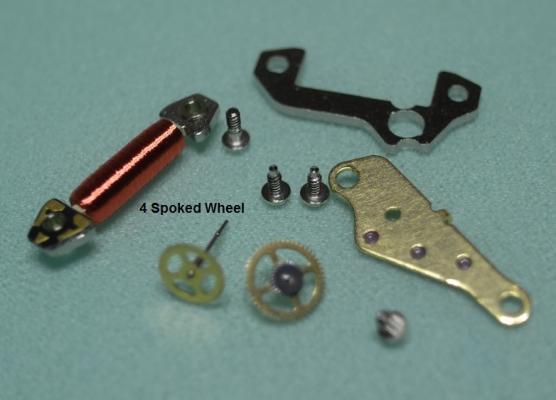
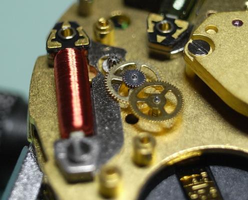
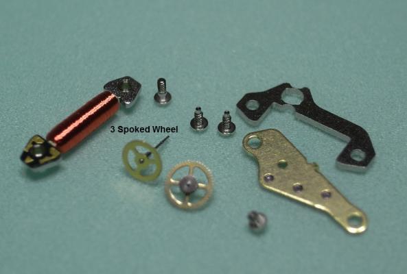
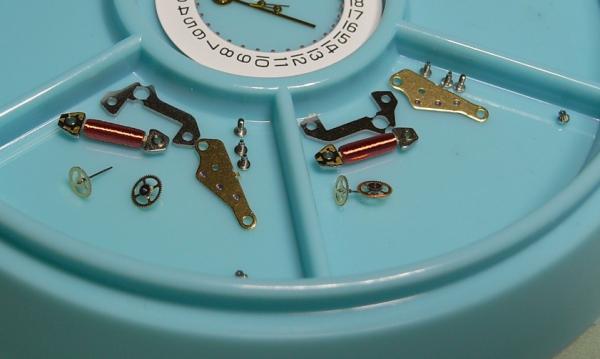
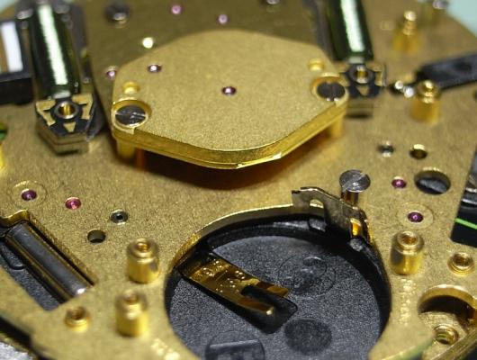
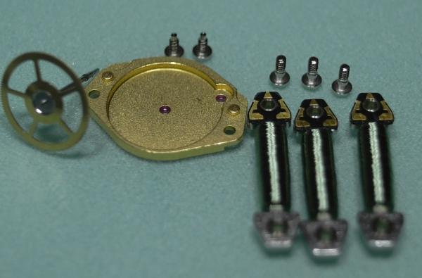
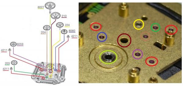
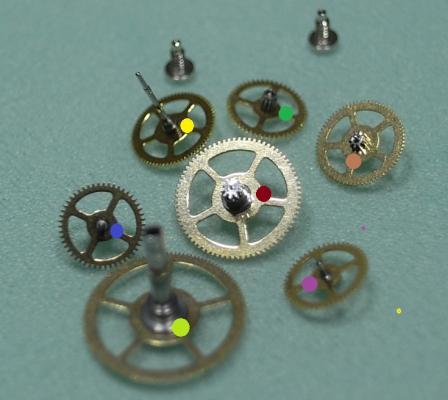
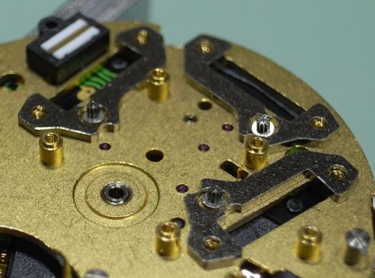
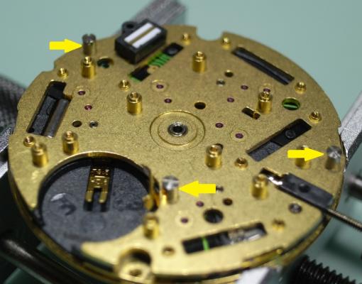
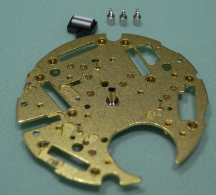
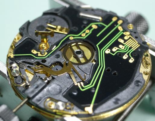
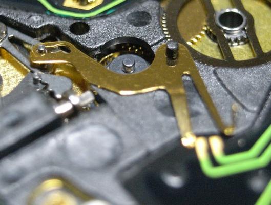
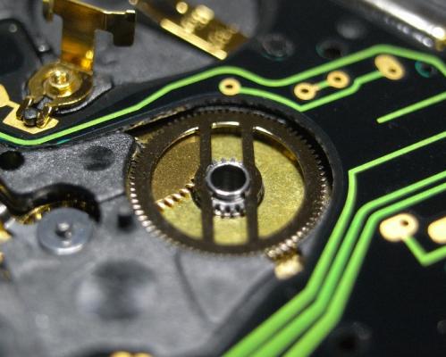
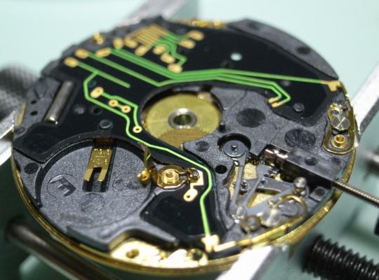
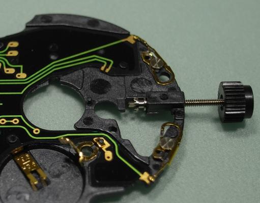
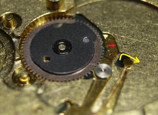
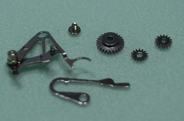
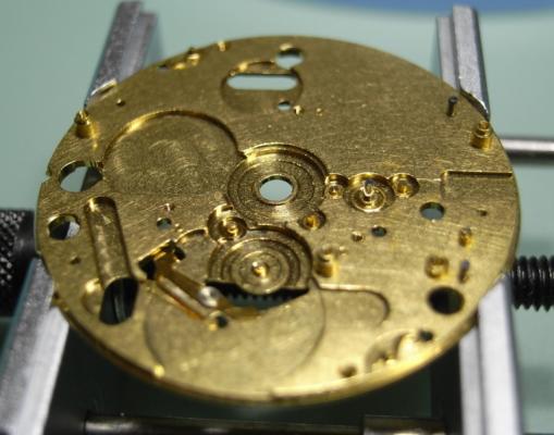
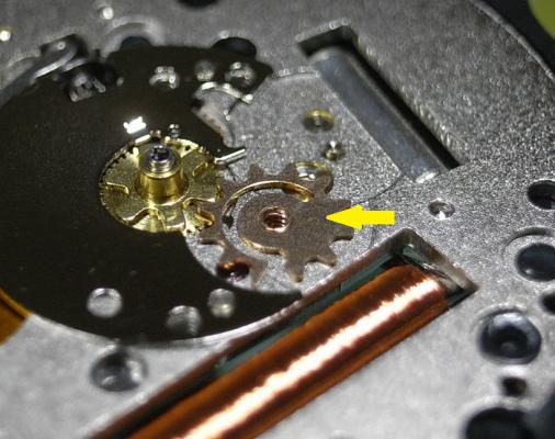
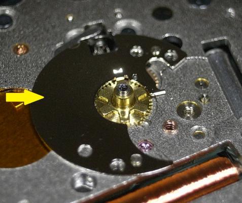
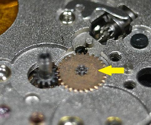
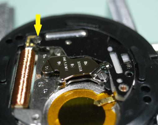
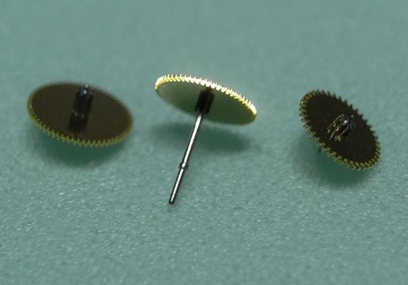
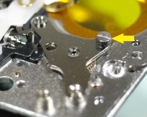
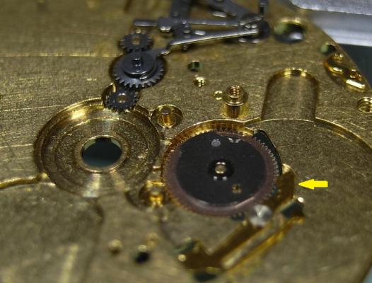
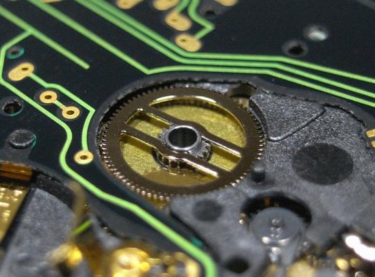
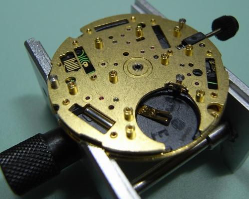
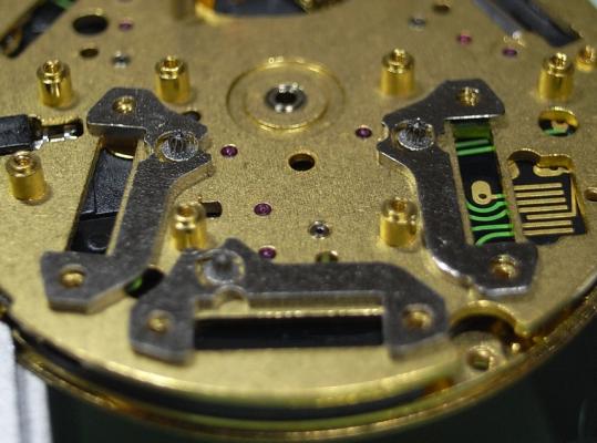
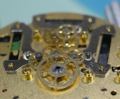
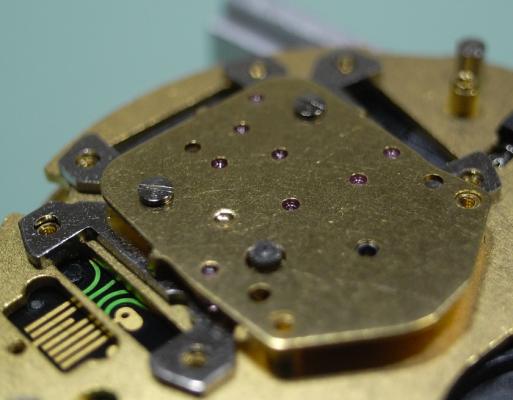
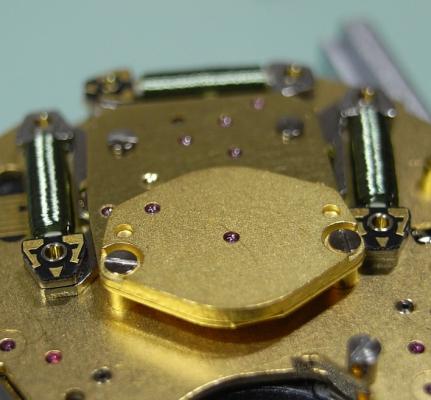
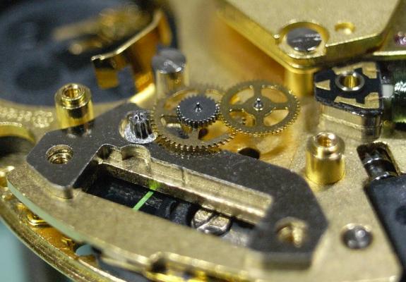
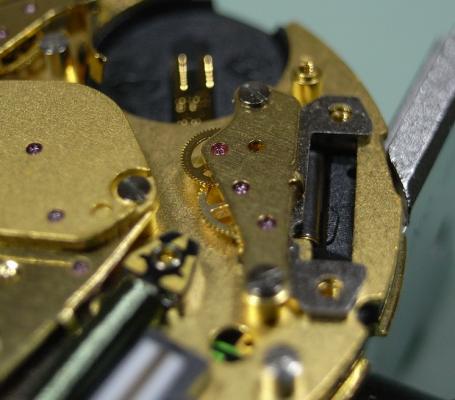
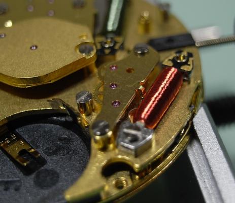
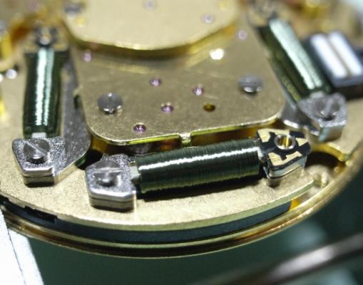
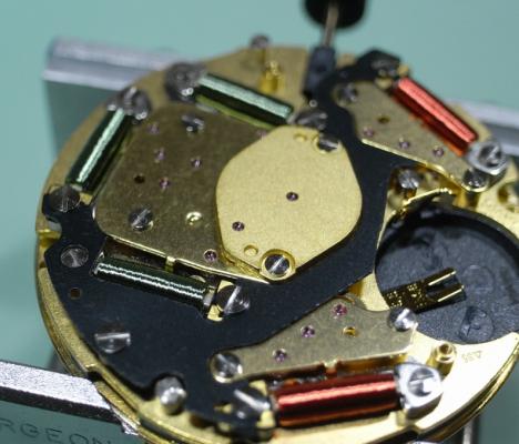
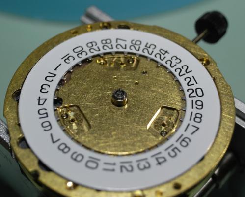
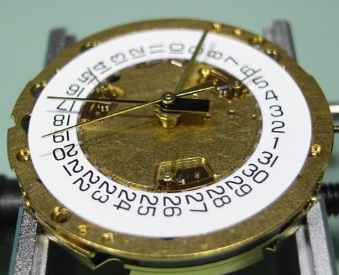
ETA 251.626 Service Walkthrough The 251.626 is often found in mid to high-end quartz chronographs on the market today. ETA 251.262.pdf It is a fairly complex quartz movement that has 5 motors, 2 with Red Coils, and 3 with Green Coils. To begin the service we start by removing the 3 Indicator Maintaining Small Plates, and Date Indicator. A 1.4mm screwdriver is all the is needed for every screw on the movement. Here's a reference photo of the 3 screws for the Indicator Maintaining Small Plates. There are no more components to remove from the dial side of the movement. Once the movement is turned over, remove the 2 screws that hold the Magnetic Screen. Once the Magnetic Screen is removed all the coils are very exposed, so work around these coils with great care. Here's a reference photo of the 2 screws for the Magnetic Screen. Next unscrew the 6 screws holding the Additional Printed Circuit and gently lift it off the movement. Store the Additional Printed Circuit away separately and safe from the rest of the parts. Here's a reference photo of the 6 screws for the Additional Printed Circuit. Next we tackle the 2 trains with the red coils. Right Side - Minute Counter Left Side - Hour Counter The right and left trains contain different size wheels and should be kept separate for ease of assembly. We shall start with the right side. Remove the Minute Counter Bridge Next remove the Gear Train and the Rotor. Next remove the Coil and Stator. Store the Coil away separately and safe from the rest of the parts. Here's a reference photo of the components and their corosponding screws. Note the 4 spokes on the Minute Counting Wheel. Remove the Hour Counter Bridge. Remove the Gear Train and the Rotor. Remove the Coil and Stator. Store the Coil away separately and safe from the rest of the parts. Here's a reference photo of the components. Note the 3 spokes on the Hour Counting Wheel. Store these 2 trains in separate sections in your parts tray, and when cleaning store them in sparate parts containers. Next remove the Chronograph Bridge Now remove the Chronograph Wheel Unscrew the Green Coils and remove them. Store the Coils away separately and safe from the rest of the parts. Here's a reference photo of the components and their corresponding screws. Remove the Train Wheel Bridge. Remove the Wheels of the Train. This is quite a complex train of wheels. So to assist you I've cleaned up the rather cluttered schematic supplied by ETA and colour coded each wheel and it's location on the Main Plate. Here's a reference photo of the top of the wheels, also colour coded to assist you. And also the underneath of the wheels, also colour coded to assist you. Remove the Rotors and Stators. Unscrew the 3 screws that hold the Upper Plate and remove it. Here's a reference photo of the Upper Plate, Connector, and the corosponding screws. This now exposes the Electronic Module. Remove the Stop Lever/Switch Remove the Cannon Pinion with Driver. Then remove the Electronic Module. Pull out the Stem and Sliding Pinion. Now store the Electronic Module away separately and safe from the rest of the parts. Remove the Minute Wheel, the Hour Wheel, and Contact Intermediate Wheel. Before we can remove the Date Indicator Driving Wheel, we need to pull back the Date Jumper. Gently lift the tab (Yellow Arrow) until it's at plate level and pull it backwards. This will pull the arm of the Date Jumper back and allow you to remove the wheel. Here's a reference photo of the wheels. Lastly we need to remove the keyless work. Unscrew the Setting Lever Spring and then remove the Setting Lever, Yoke, Driving Wheel, Internediate Setting Wheel No.1, and the Setting Wheel Here's a reference photo of the Keyless Work. The movement is now completely disassembled. I hope you've enjoyed this disassembly walkthrough and found it's given you the information and confidence to tackle this tricky but rewarding quartz movement. I will post the assembly procedures tomorrow, Lord willing :)


 1 point
 -
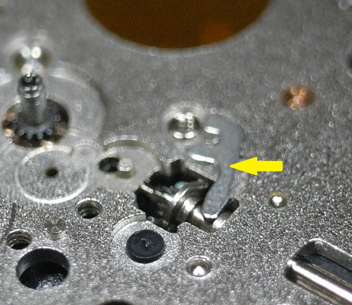
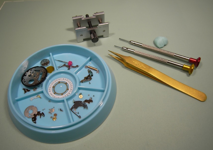
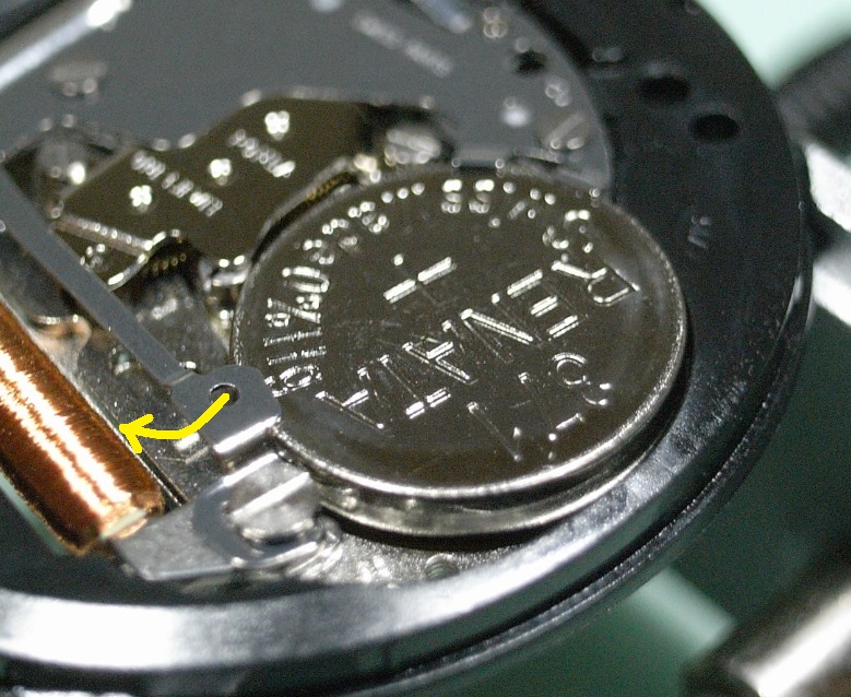
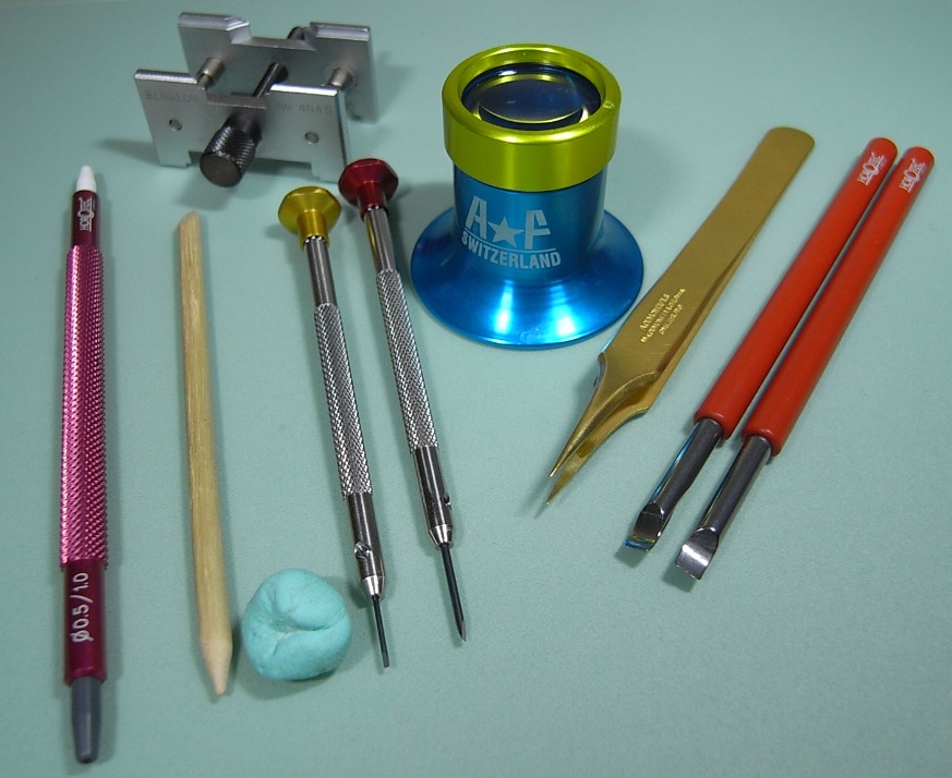
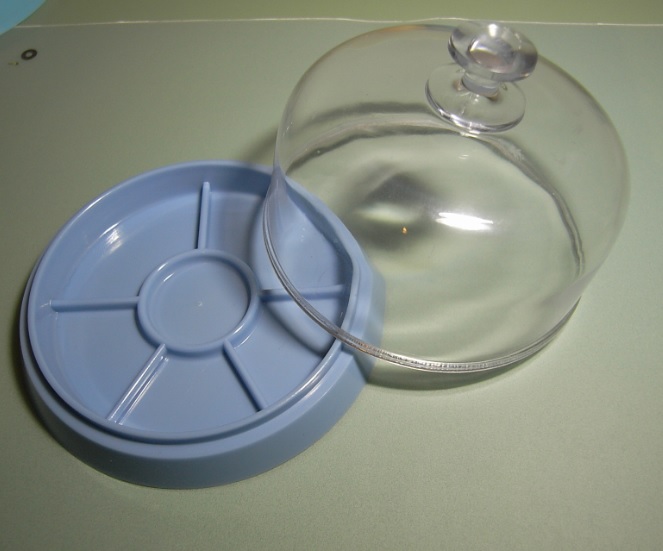
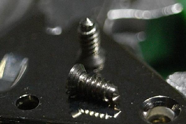
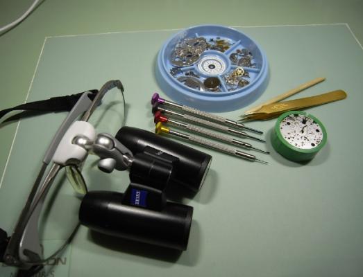
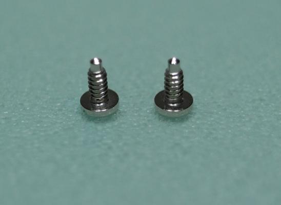
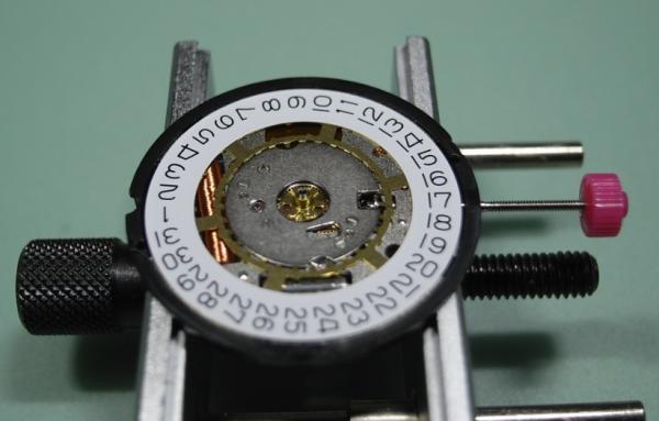
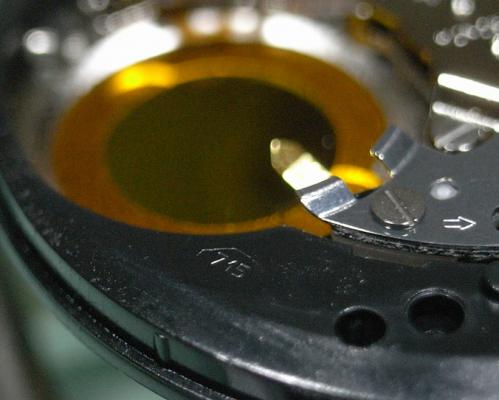
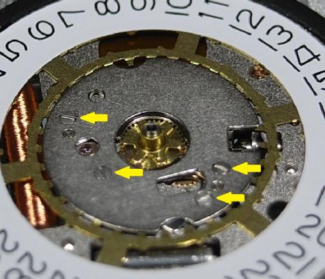
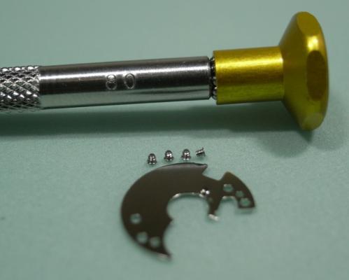
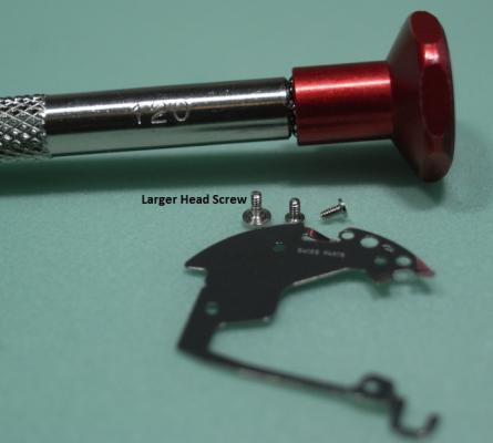
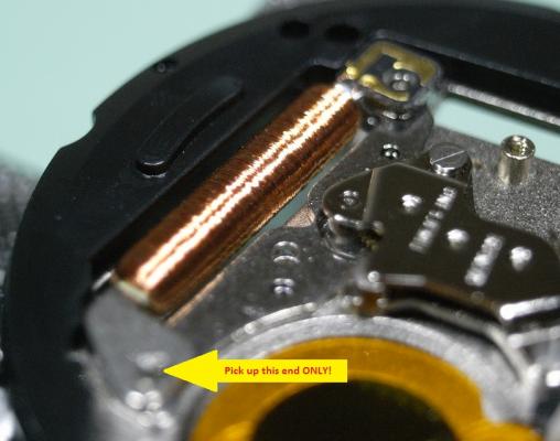
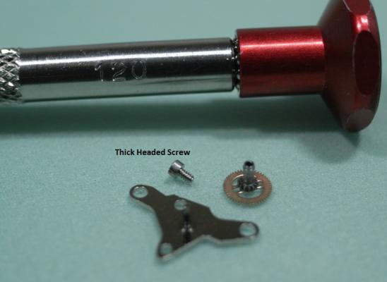
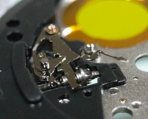
Ronda 715 Service Walkthrough I thought I'd post a walkthrough on a simple quartz movement for people who are just starting out in watch repairing. The Ronda 715 is an excellent movement to begin with, as it's simple in design; but has all the components needed to practice your skills on. Even better is that it only cost around $10 to buy this movement brand new online. So if you break it or loose a part, you learn from the experience, and just buy another one :) Perfect!! The Ronda 715 is found in many of the "Fashion" brand watches, like Guess, JAG, Loyal, etc... As this is a walkthrough for novices there will be arrows to every part as we disassemble this movement. I also recommend you download the Tech Spec PDF and get familiar with how to read them. Here's the link to down the PDF 559_Ronda702,703,705,708,712,713,715.pdf Remember to have fun!! :lol: If you start to get frustrated, just have a break and come back to it later. Patience and perseverance will get you there, and once the skills are mastered it's very rewarding. Ok, lets begin Firstly, you identify this particular caliber of movement by the number stamped into the plastic surround. As you can see this one is stamped "715" The tools you will need for this service are as follows: Bergeon 4040 Movement Holder An Eye Loupe, or some type of optics 3x or better Pegwood 0.8mm Screwdriver 1.2mm Screwdriver Tweezers Hand Lifters A Hand Setting Tool A Parts Tray with cover And a piece of Rodico Since I am using a movement purchased from CusionsUK, I unfortunately don't have Hands or a Dial to remove. If you are servicing a movement presently in a watch, I suggest you watch one of Mark's video's to see how you remove Hands and the Dial. Mark's Videos are a fantastic resource to show you proper technics, and I highly recommend viewing them. They can be found here: https://www.youtube.com/user/jewldood/videos Once the Hands and Dial are removed, we then need to remove the battery, if one is installed, before we begin disassembly. On this movement it is done by gently pulling the Keeper Arm back away from the battery. Be careful when doing this so that you don't slip and damage the Coil. Then turn the movement over and remove the 4 screws, using a 0.8mm Screwdriver, that hold down the Date Indicator Guard, and remove it. Here is a reference photo of the Date Indicator Guard and screws. Next, hold down the Jumper Spring with Pegwood to stop it pinging away, and remove it with your tweezers. Then remove the Date Jumper and Date Indictor Ring. Next remove the Indictor Driving Wheel Then the Date Indicator Plate Followed by the Hour Wheel. Next remove the Setting Wheel Remove the Minute Wheel Remove the Secondary Yoke This completes all the components on the dial side of this movement. Turn the movement over in the holder. Unscrew the 3 screws, using a 1.2mm Screwdriver, that holds the Module Cover Plate, and remove it. NOTE: One of the screw is unique and larger than the others, remember it's location. Here is a reference photo of the Module Cover Plate and the 3 screws. Next remove the single screw that holds the Circuit and the Coil. Then remove the Circuit VERY carefully and store it somewhere very safe. Here is a reference photo of the Circuit and screw. Next remove the Coil by lifting it with the end with no circuit tracks on it, as shown below. Now unscrew the 2 screws, using a 1.2mm Screwdriver, that holds the Train Bridge and lift it off gently. Here is a reference photo of the Train Bridge and screws. Next remove the wheels of the train carefully, then the Rotor and Stator. From left to right there names are: Third Wheel, Second Wheel, and Intermediate Wheel. And here are the Rotor and Stator. Unscrew the single screw, using a 1.2mm Screwdriver, that holds the Centre Bridge and remove it. The Cannon Pinion should be on the centre post of the bridge and come away with it. NOTE: This screw is also unique with a thicker head, remember it's location. Here is a reference photo of the Centre Bridge, Cannon Pinion and screw. Next remove the screw, using a 1.2mm Screwdriver, that holds the Plastic Setting Lever Cover, and remove it. Here is a reference photo of the Setting Lever Cover and screw. Then lift out the Setting Lever and Primary Yoke. Lastly, pull out the Stem and the Sliding Pinion should fall to your work mat. You have now completely disassembled the movement ... WELL DONE!! :) The black plastic outer ring can not be removed, it is riveted to the Main Plate All the parts can be put in the cleaning machine or Ultrasonic ... EXPECT THE FOLLOWING PARTS! Battery Circuit Coil Rotor I hope this was a fun movement to begin your journey into watch repairing, and that it builds your confidence to advance further. Assembly will be posted soon...stay tuned!


 1 point
 -
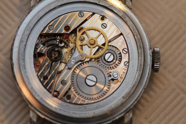
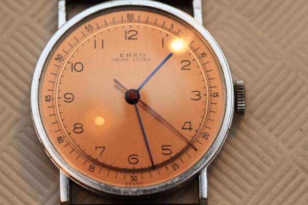
Today i'm wearing an "Erso" with a copper dial which I just finished servicing. Can't decide whether I like it or hate it.. but the ETA 810 movement sure is pretty!
 1 point
 -
Vitaly, if you're going through that much trouble to make sure the watch is as it should be, and you would describe yourself as a complete novice, then that leads me to think this might not be a watch you want to attempt a service on, that being said you're free to do as you like and you will always find help here. In regards to the buckle, it's entirely likely that stainless steel buckles were mass produced and stamped and then they would take a portion of those stainless buckles and have them plated.1 point
-
A rather expensive way of screwing anything.1 point
-
it is quite difficult to do this on the inner coil of the mainspring. It may be better to purchase a new one.1 point
-
+1 WillFly. I knew a music teacher who described 4 stages of learning Unconscious Incompetence (you don't know you're crap) Conscious Incompetence (you know you're crap) <--me Conscious Competence (you know you're good but you need to work at it!) Unconscious Competence (Nirvana!) Hairsprings are, it must be said, evil, evil things. I feel your pain.1 point
-
No worries! If I had a tenth of your technical knowledge, I'd be a happy man.1 point
-
Hi, With the help of your photos the picture is absolutely clear now. I guess we went through the same path. The movement I am working on shows: 158 31/7 and based on that I ordered the wrong balance. With your photos I am now confident to order the 1582793. I also ordered the regulator for that watch and again, the one I received was way to short. I will post photos and movement analysis when I complete the project. Thanks again!1 point
-
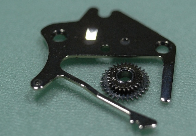
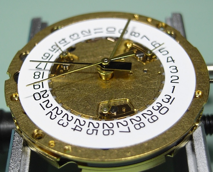
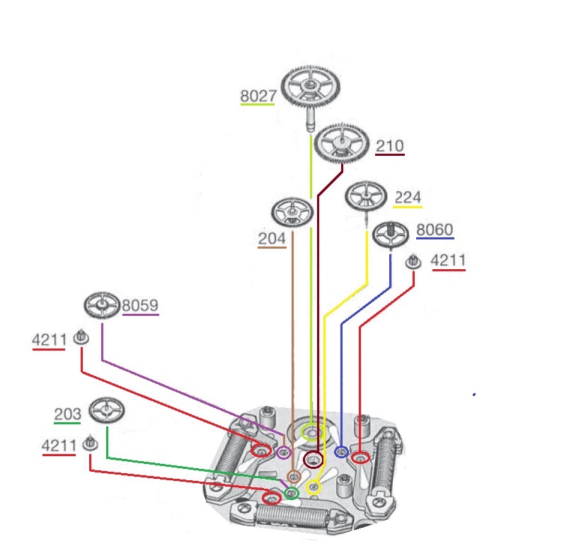
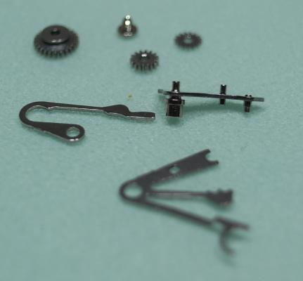
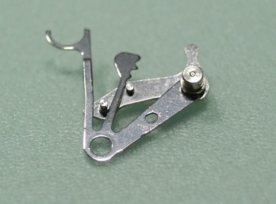
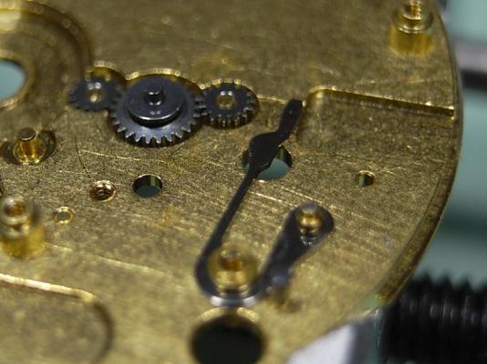
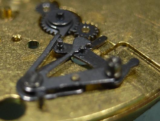
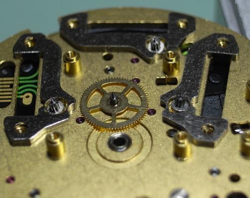
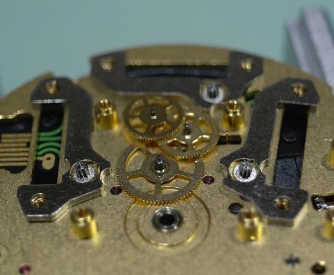
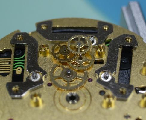
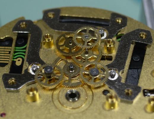
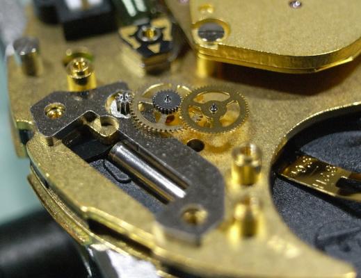
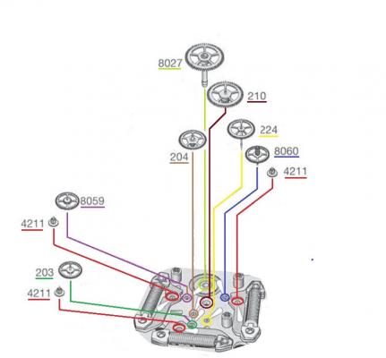
ETA 251.626 Service Walkthrough Part 2 Assembly We begin the assembly with the keyless work. Fit together the Setting Lever and Setting Lever Jumper. Then install the Driving Wheel, Intermediate Setting Wheel No.1, and the Setting Wheel Install the Yoke Then slide the saddle at the end of the Setting Lever Jumper Arm into the groove in the Intermediate Setting Wheel No.1. You will have to then lift the Intermediate Setting Wheel No.1 slightly to position the Setting Lever Assembly as shown below. Then locate the Setting Lever and Jumper onto their respective posts and slots. Once screwed down engage the position arm of the jumper onto it's post on the Setting Lever. Next install the Date Indicator Driving Wheel. Remember that you need to slide back the Date Jumper Once the Date Jumper is back in position check that the spring arm is once again down in it's correct position. Install the Contact Intermediate Wheel, the Hour Wheel and then the Minute Wheel. Replace the Electronic Module, then fit the Sliding Pinion and the Stem. Install the Cannon Pinion with Driver. Replace the Stop Lever/Switch. Then gently place the Upper Plate back on the movement, making sure the Yoke and Setting Lever are positioned correctly, and that you do not disturb any of the other components underneath. Refit the bank of Stators and Rotors which have the Green Coils. Now we come to the trickiest part of this service: installing the Main Gear Train. To assist in the order in which to install the wheels I will give the part numbers, and colour code the text, to match that of the diagram above. Start with the Third Wheel [210]. Then the Additional Intermediate Wheel [204] Then the Second Wheel [224] Then the Intermediate Wheel [203] Then the Driving Wheel for Second Counter [8059] Then the Driving Wheel for Chronograph Wheel 60s [8060] And lastly replace the Counting Wheel for Seconds or Minutes [8027] Once the train is in place, take some time to tweak the wheels so that are standing up as straight as possible. Remember that you have 10 pivots to align with their respective jewels, so taking some time to position the wheels and rotors now can save you a LOT of frustration fitting the Train Wheel Bridge. I would go so far as to take a little break, have a drink, relax your muscles and mind before proceeding to the next step. Fit the Train Wheel Bridge and align all the pivots to their jewels, and check the free running of all wheels before tightening down only the 2 rear screws. Install the Chronograph Wheel. Next fit the Chronograph Bridge and align the 2 pivot points to their jewels. This has to be done without the ability to manipulate the wheels directly, so make sure you inspect the jewels with high magnification to be sure the pivots are in their holes. And again, check the free running of the train. Replace the Connector Next we will install the small trains for the Counting Wheel, 1/10s and Hour Counters. These are the ones with the Red Coils driving them. Remember that the wheels are specific for each train and should have always been separated ... DO NOT MIX THEM UP. We shall begin with the right side. Install the right side Stator and Rotor for the 1/10s Counter. Next replace the Driving Wheel for Counting 1/10s [8059/1] Then replace the Counting Wheel, 1/10s [8027/1] Note this has 4 spokes to the wheel. Fit the Counting Wheel Bridge, making sure to align the pivots and test the free running before tightening. We repeat the process for the left side Hour/Minute Counting Train. Install the right side Stator and Rotor for the Hour/Minute Counter. Replace the Hour/Minute Counter Driving Wheel [8630/1] Then replace the Hour/Minute Counting Wheel [8600/1] Note this has 3 spokes to the wheel. Fit the Hour/Minute Wheel Bridge, making sure to align the pivots and test the free running before tightening. Fit the Red Coil to the right side Counting Wheel Assembly and screw down. Fit the Red Coil to the left side Counting Wheel Assembly and screw down. At this stage also screw down the 3 Green Coils. Refit the Additional Printed Circuit. Replace the Magnetic Screen. Secure the Battery Clamp. Then turn over the movement to the dial side. Fit the Date Indicator. And secure the Date Indicator with the 3 Indicator Maintaining Small Plates. Then fit the dial and hands and test all the functions of the movement. ETA 251.262 operating instructions.pdf The service is complete. As always, I hope this walkthrough was informative and instructive, and gives you the confidence to complete this service on your ETA 251.626


 1 point
 -
Here's a very interesting piece on what Seiko did to "upgrade" the 7s26 to 6r15. Http://seikoholics.yuku.com/topic/48/Inside-the-Seiko-6r15-with-a-comparison-to-the-7s26-1 point
-
Yes, Hattori is a subsidiary of Seiko, named after Seiko CEO Shinji Hattori. I'm not sure but, I think when they decided they were going to sell movements to other watch manufacturers they didn't want the conflict of having their watch brand name 'Seiko' in non Seiko watches, because it might lead to intellectual property issues and also lead to people thinking Seiko make Animal watches and such, Hattori is basically their line of movements for the general watch manufacturing market, at least that's the best guess I can make.1 point
-
When i was swimming i use to put spit my googles to stop them from fogging up . But i am not sure it works in the loupes ? :)1 point
-
Lawson, when do you find time to sleep? I know how long it takes me to put together a walk through and mine have only a fraction of the detail that yours do. This is yet another excellent publication, many thanks for time and effort that you must put into them. Your photography and presentation are absolutely of the highest.1 point
-
Witschi Has some other things on timing you might find interesting. First one is kind of similar to the other link but different. The second PDF explains were all those numbers come from related to timing. Test and measuring technology mechanical watches http://www.witschi.com/assets/files/sheets/Test%20and%20measuring%20technology%20mechanical%20watches.pdf Calculation of the values X-D-DVH-Di-Im-N http://www.witschi.com/assets/files/sheets/Calculation%20of%20the%20values%20X-D-DVH-Di-Im-N.pdf The problem with the watch are working on is it is really small. The problem with really small watches is everything becomes super critical.1 point
-
Any improvement in art and skill is a case of two steps forward, one step back, with various plateaus at to be scaled as you progress. It's exactly the same playing a musical instrument - and I've been playing several for over 50 years! I've been playing a tune for years - and then I fumble, for no reason, at a particular spot, and it takes a while to sort it out again. As Affnan says, relax, take five, and start again.1 point
-
It sounds familiar. Try this solution from Lawson: http://www.watchrepairtalk.com/topic/1272-a-hairspring-puzzle/ Good luck - sometimes a little of this is needed.1 point
-
A note regarding the missing regulator it's not missing. Regulators cause timing problems free sprung balances don't have that problem so Elgin came up with a innovative solution to the regulator problem the Durabalance. The unfortunate problem with their solution is it tends to frustrated and confused the watchmaker who probably never seen one of these before. Fortunately it is in the service manual which can be found at the link below. http://www.flynwill.com/Watches/ElginManual/ElginMan18.htm Then a note regarding the timing machine it's not going to really show any meaningful numbers unless it's over 200° amplitude. When the watches been freshly serviced it should be much closer to 300° only falling into the 200 range at the end of 24 hours running. Trying to regulate the watch when the amplitude is way below 200° will definitely not be a good thing for you. Here's a link to a PDF with a lot of useful information even though the timing machine is different the information is still valid. http://www.witschi.com/assets/files/sheets/Witschi%20Training%20Course.pdf When you cleaned the watch did you remove the mainspring from the barrel?1 point
-
Get yourself a large steel or brass washer, big enough for the hole to be slightly smaller than the inside diameter of the mainspring barrel. Wind the mainspring into your winder, left handed or right handed, it doesn't matter. Install the mainspring into the hole in the washer. Transfer mainspring from washer to barrel as you would a new mainspring. Save yourself a fortune by equipping yourself with a good selection of large washers.1 point
-
I think its more of a question of which press rather than which dies. A poorly made press will have a greater risk of damaging a watch regardless of the die used.1 point