Leaderboard
.thumb.jpg.cb17a66989f1e796fd4217db2e9ca9df.jpg)

Popular Content
Showing content with the highest reputation on 06/19/24 in Posts
-
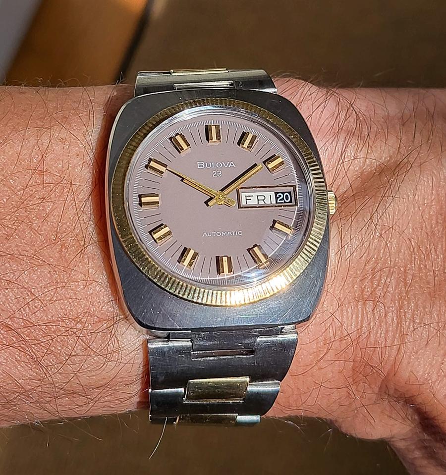
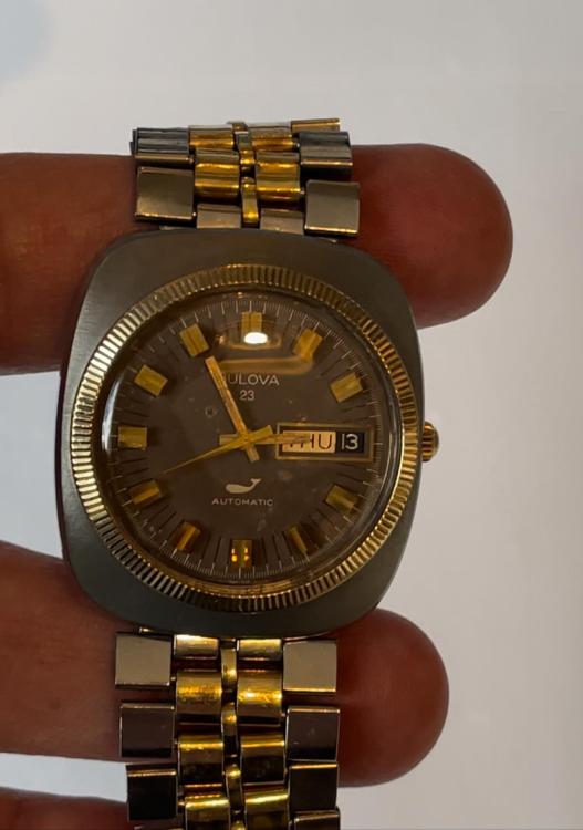
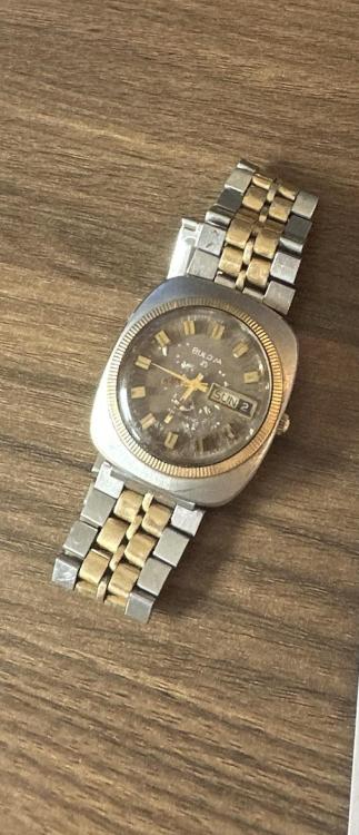
Restored as best I could with original dial/hands/case and numerous NOS parts my son-in-laws father’s Vietnam era bulova 11AOACB watch. lot of time spent into getting the case, dial, bracelet and hands sorted due to significant salt water corrosion (he was in the navy). Movement had numerous rusted parts, mostly in the motion and dial works. Fortunately a salvage movement was available as well as NOS parts from McCaw’s in the US. It is a sentimental piece, so visual perfection wasn’t he wanted wanted—he intends to wear it as his father did over 50 years ago (like all old bulovas after being serviced, runs really strong).

 6 points
 -
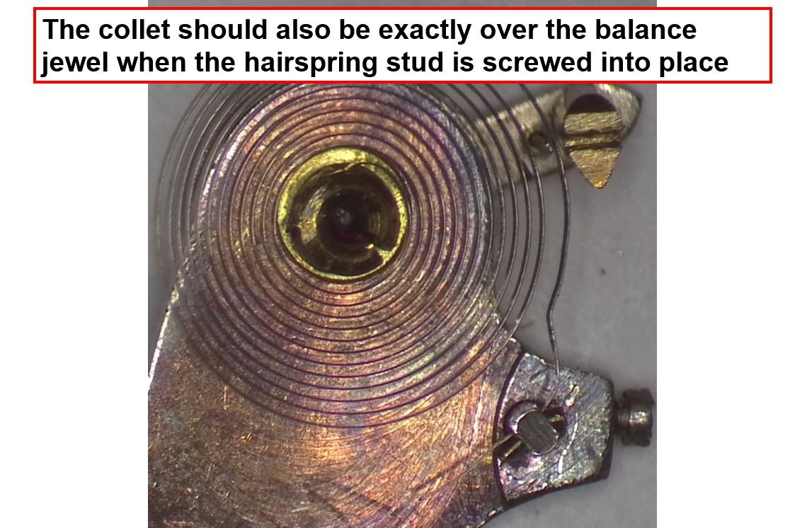
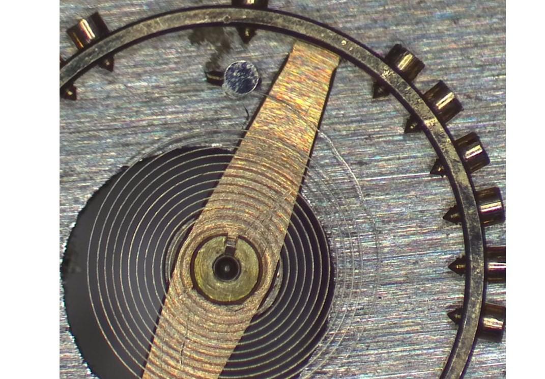
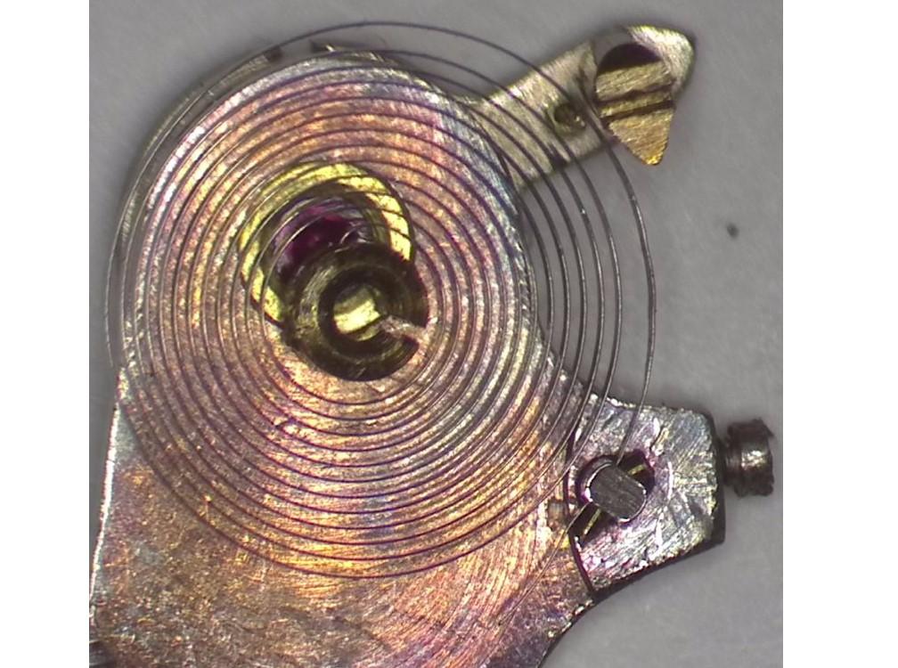
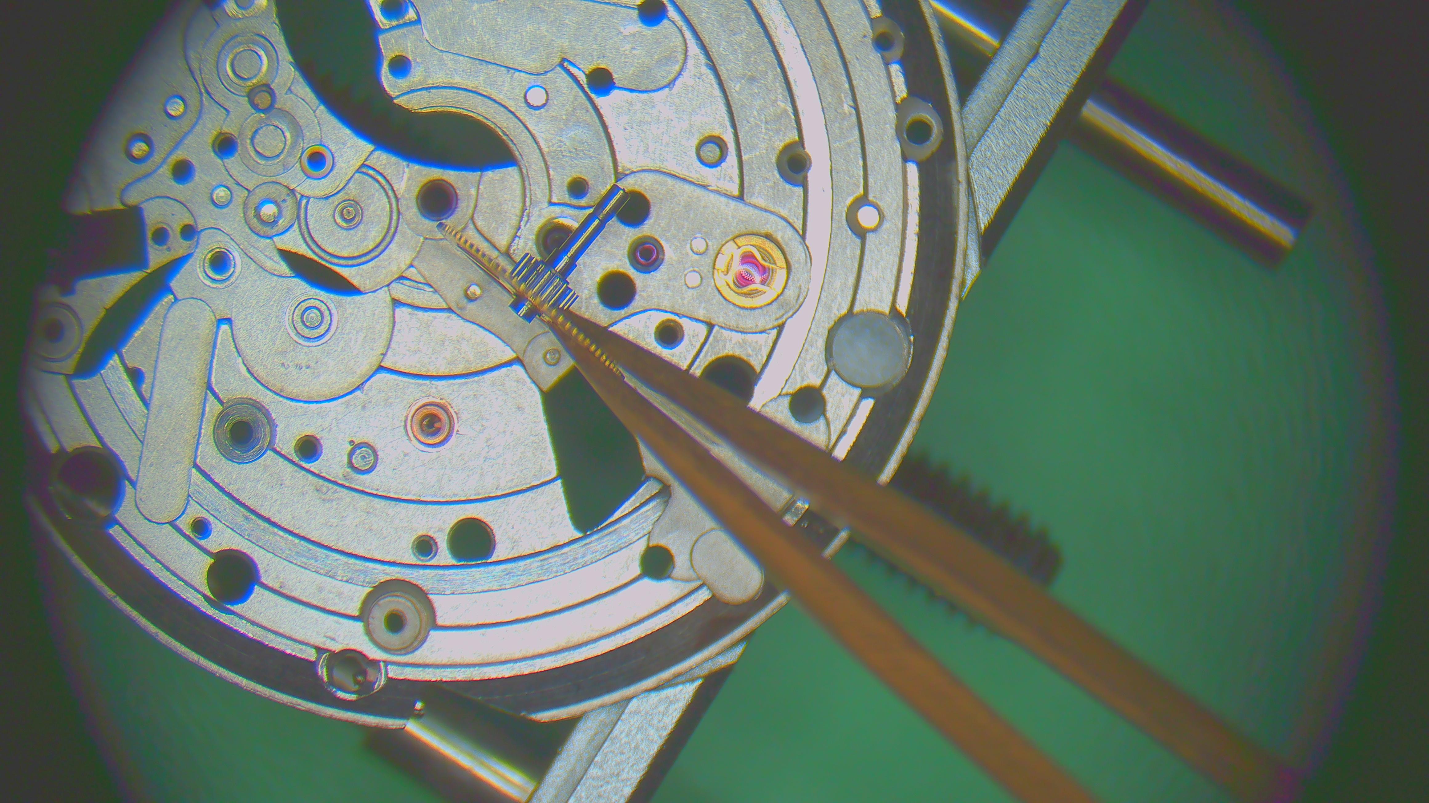
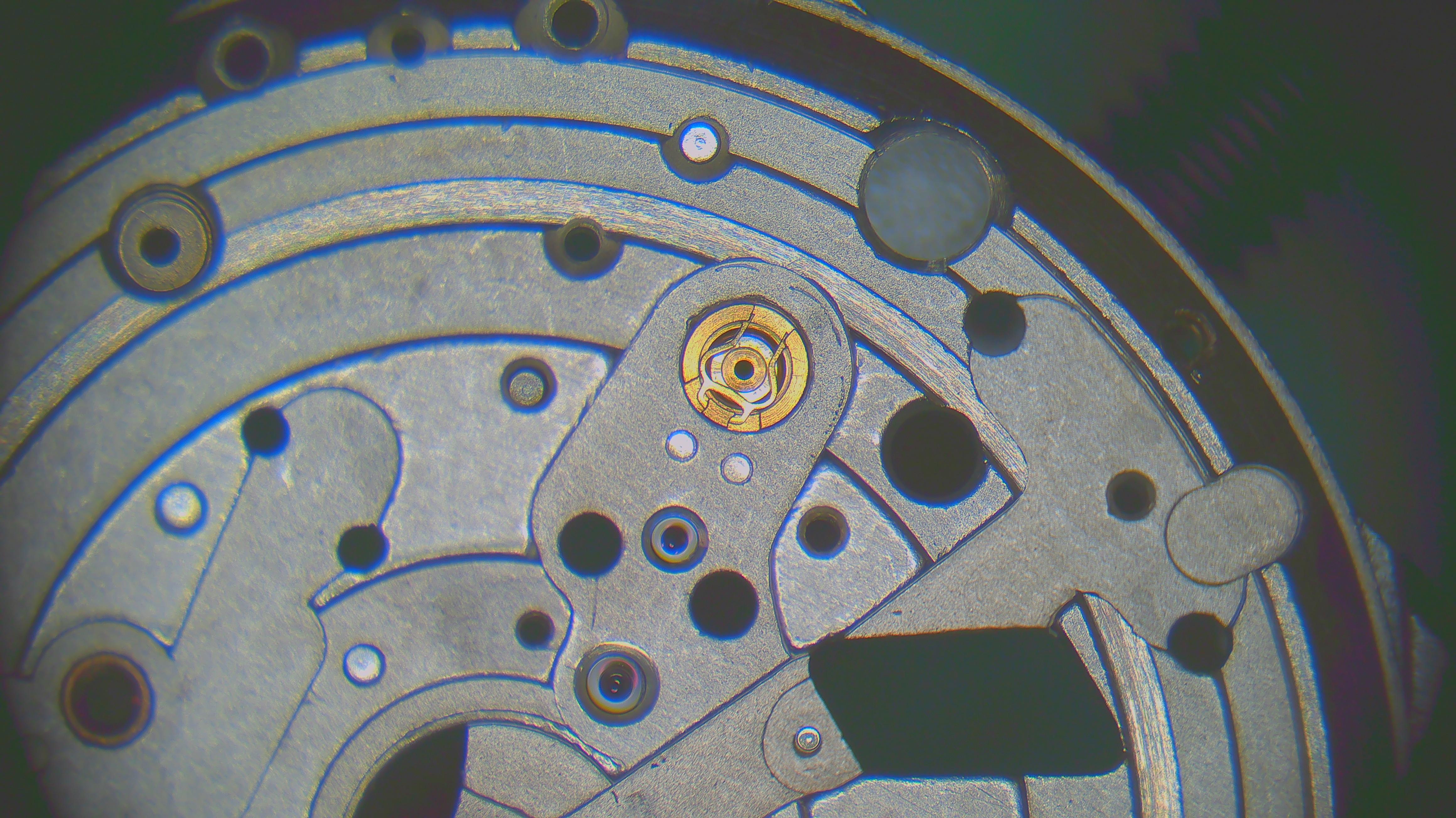
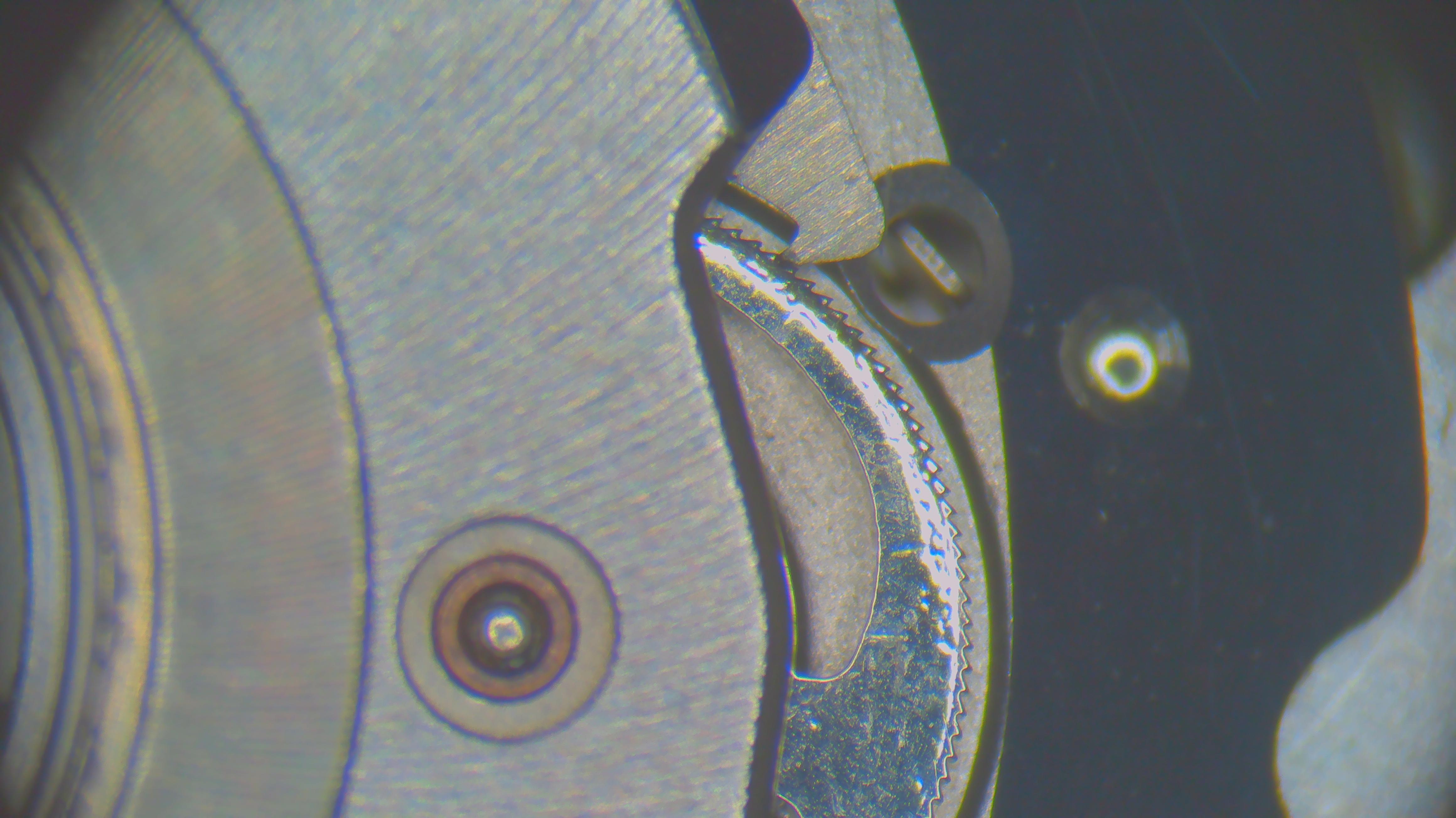
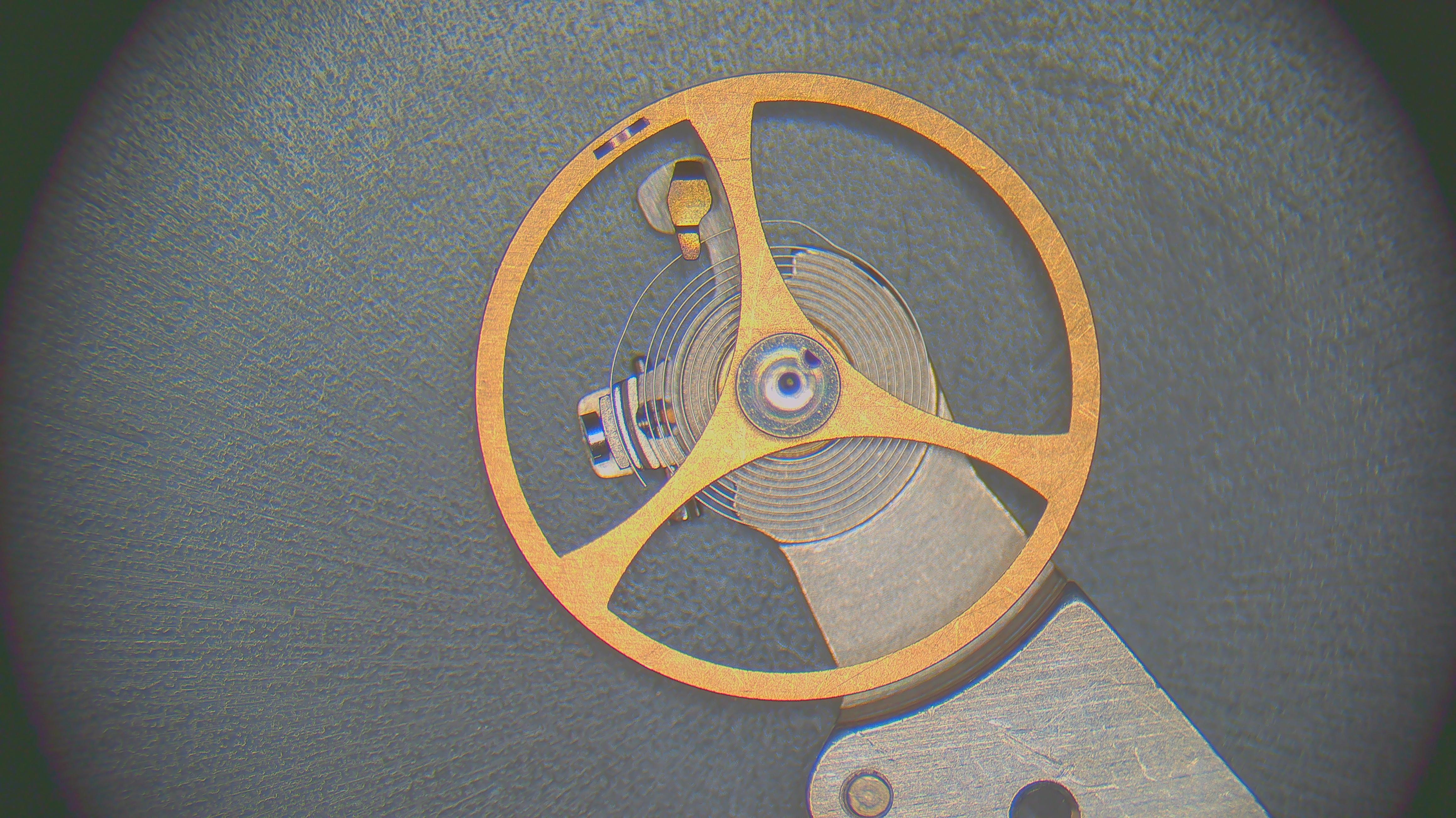
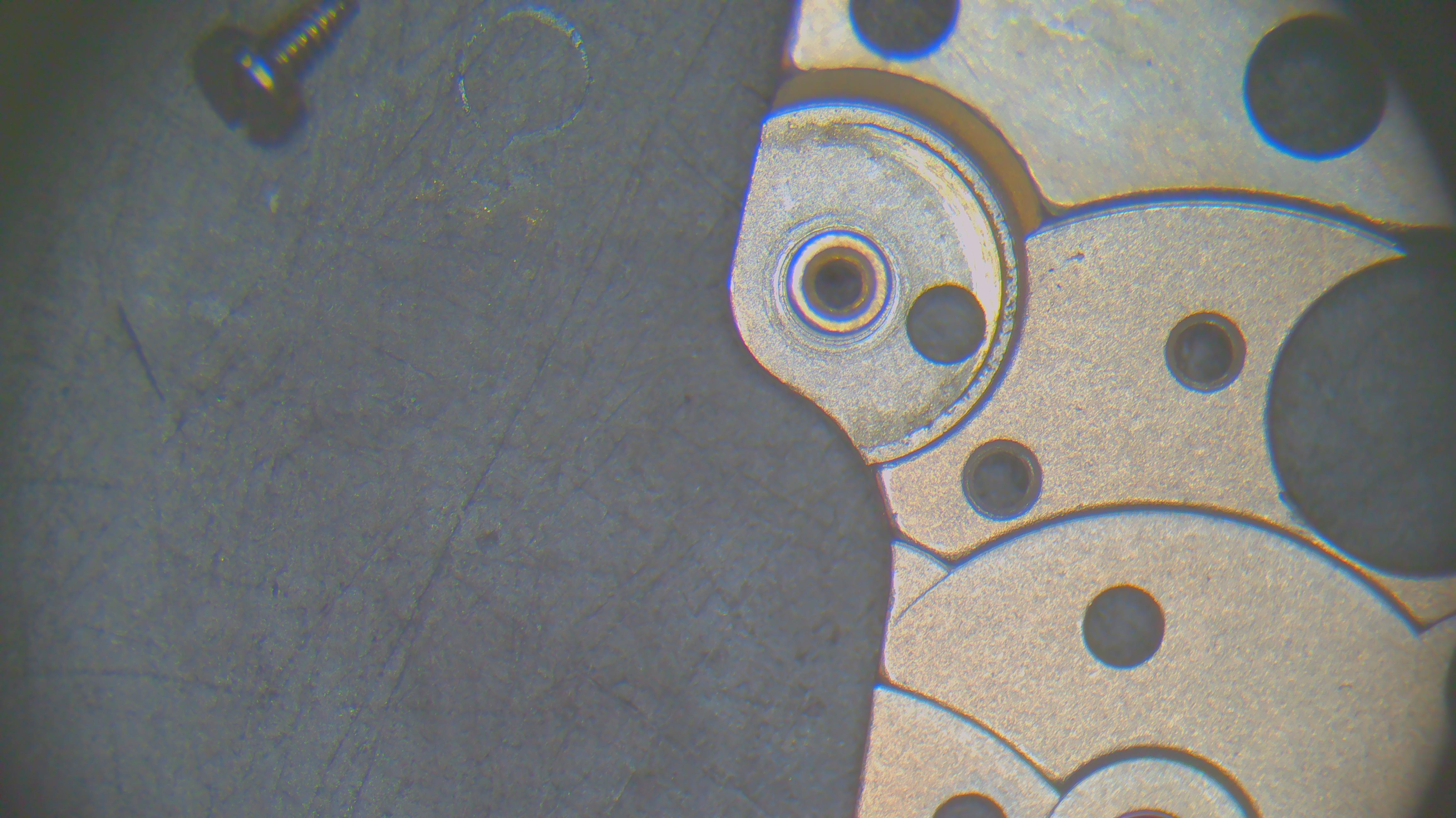
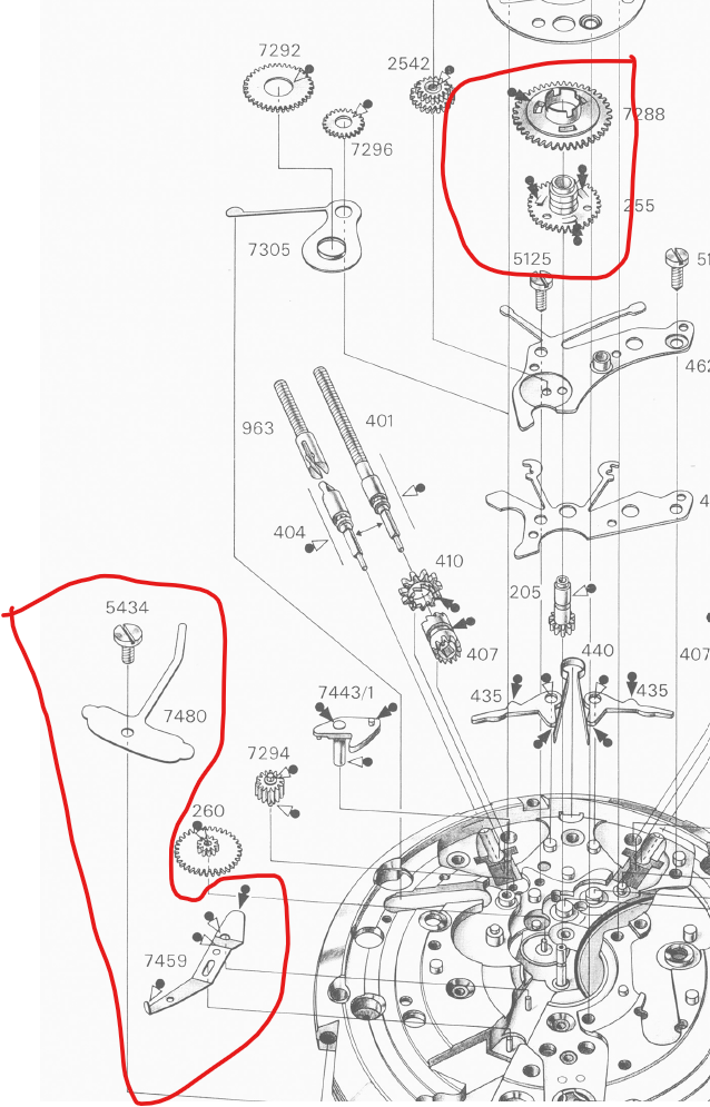
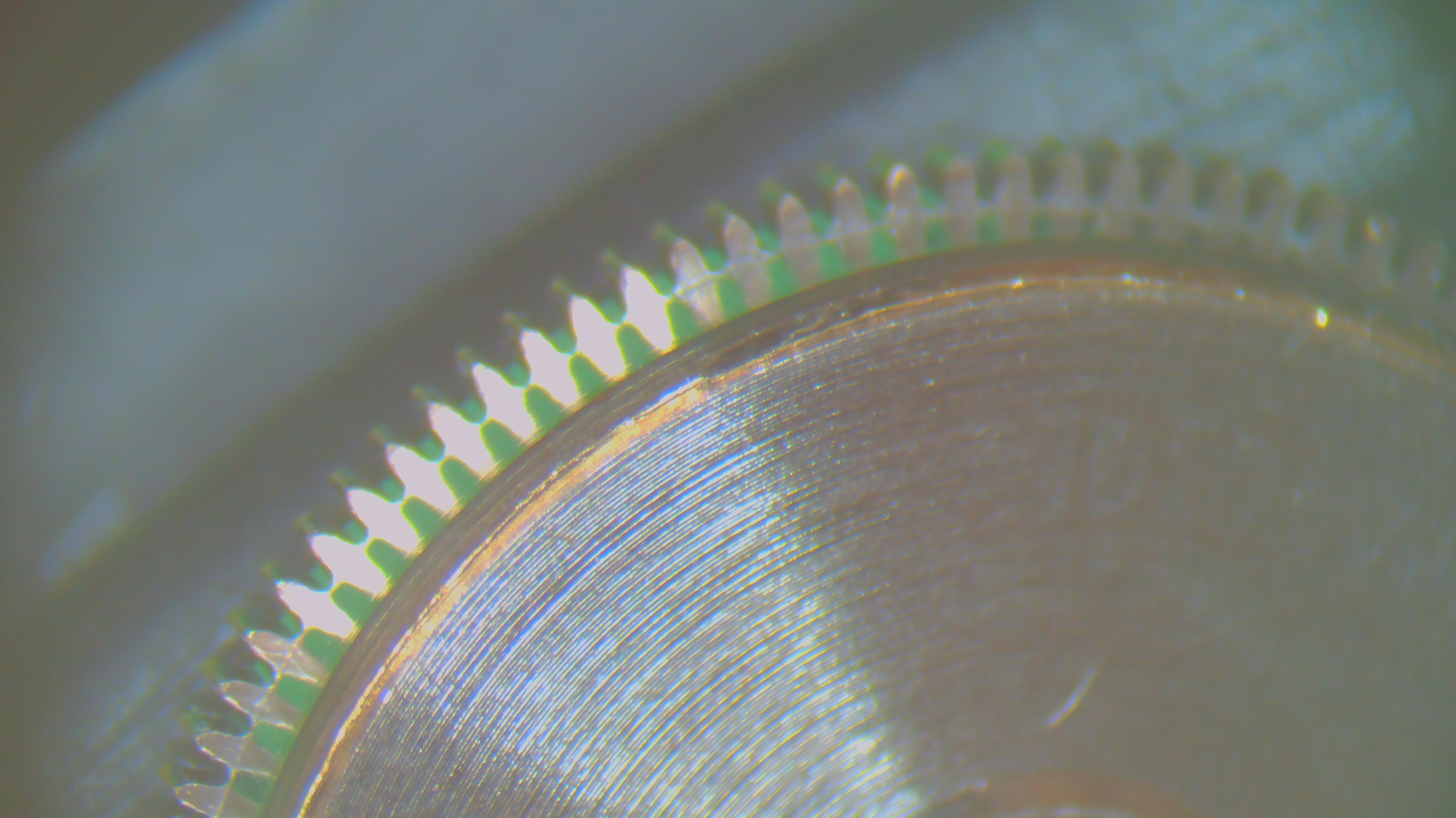
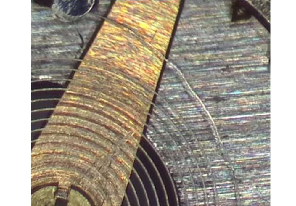
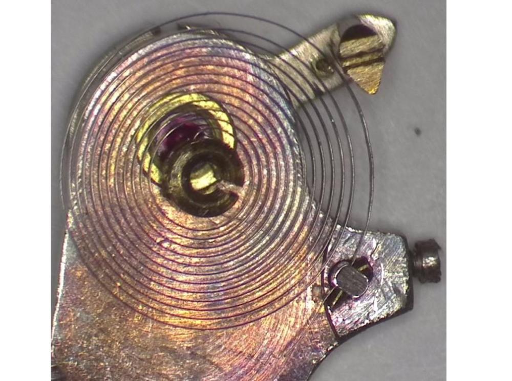
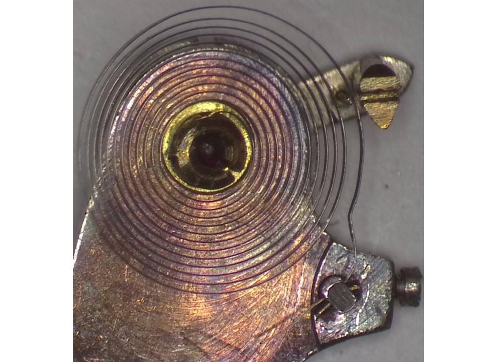
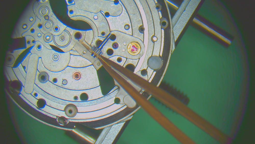
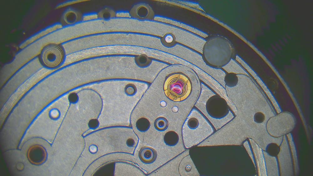
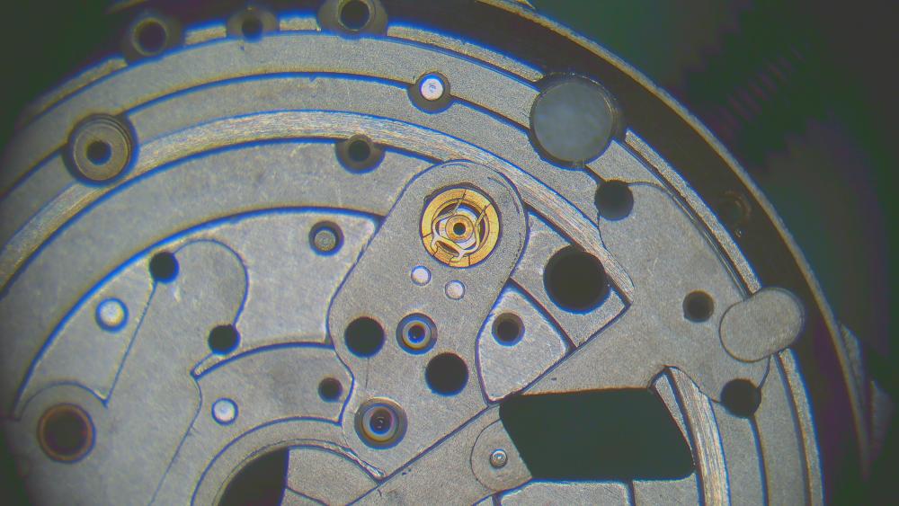
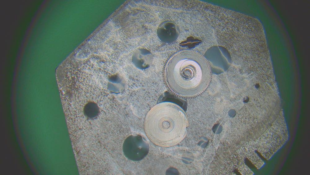
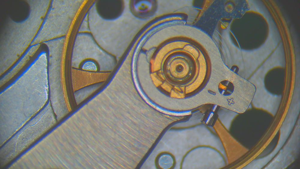
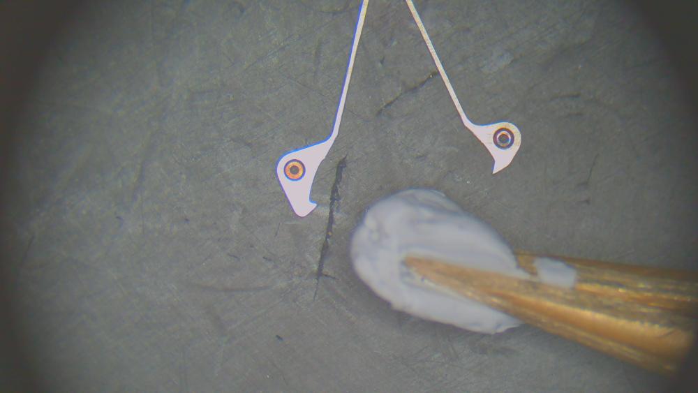
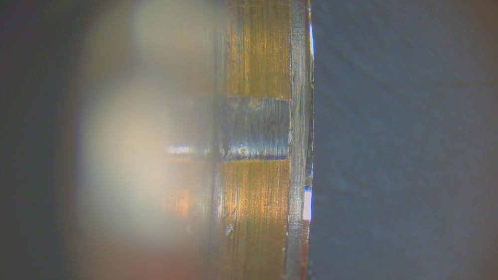
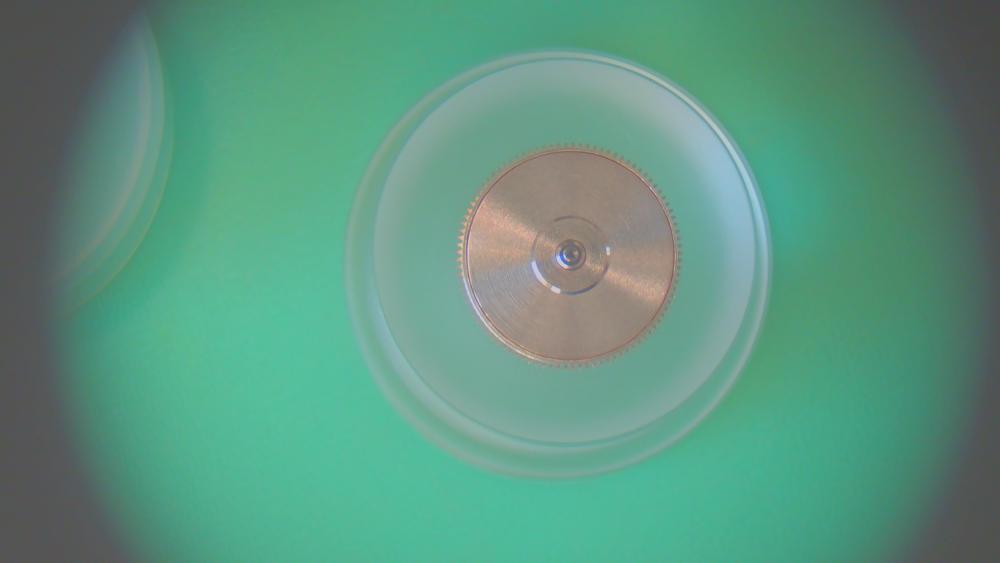
The only real way to know if the hairspring end-curve, collet position, etc are correct is to remove the hairspring from the balance and place it over the underside of the balance cock to see if everything lines up. The first pic is a hairspring with a gentle end-curve. Where the second coil is close to the regulator pin (curb pin) is of no worry, because a flat hairspring such as these don't breath much at that one side, only free-sprung and Breguet hairsprings have an even expansion and contraction on all sides. Don't get hung up on what you think you can and can't do to a hairspring to get it to sit correctly as in this slide. if it requires a kink just before the stud, then do it, but be very sure where the bends need to be to get the hairspring constantly between the regulator pins (pic 1) and the collet bang on over the balance jewel (pic 2) This is one I did recently, where the end-curve was way out with lots of little kinks in this part of the spring, which needed addressing first. So, once the kinks have been removed and the end-curve formed, then I can think about getting the collet over the jewel and keeping the hairspring between the regulator pins, because left like this a big changes in beat error will be the evidence the collet isn't central when the index is moved from extremes of 'advancing' or 'retarding' So, I worked out some bends close to the stud were required. I'm not getting side-tracked thinking the spring wasn't like this to begin with, so why am I putting such extreme bends into it to get it to work properly, as that is assuming anything was correct to begin with. And, I know doing what I'm doing is going to work, so I'm not interested in how it was, because how it was didn't work! The last pic with the acute bends near the stud worked a treat and the second coil closest to the curb pin hardly breathes on that side, so doesn't touch the curb pin, but it is always good to check if that is happening. I hope the pics help. As long as the hairspring is true on the flat when the stud is screwed to the stud holder on the balance (very important to screw up to gain the correct position as the stud positions itself) and the coils are evenly concentric and the end-curve is formed so the regulator pins don't ever push or pull them in the extremes of the index and the collet is exactly over the jewel and ensuring the second coil doesn't touch the curb pin, then your ready to attach it back to the balance and see the fruits of your labour! But before you do, move the index from left to right and make sure the hairspring remains central and doesn't move. Until you have ensured the hairspring is in this condition, as in the end slide, there is no need to touch the curb pin in my experience. It looks fine. Exactly!


 5 points
 -
Restored as best I could with original dial/hands/case and numerous NOS parts my son-in-laws father’s Vietnam era bulova 11AOACB watch. lot of time spent into getting the case, dial, bracelet and hands sorted due to significant salt water corrosion (he was in the navy). Movement had numerous rusted parts, mostly in the motion and dial works. Fortunately a salvage movement was available as well as NOS parts from McCaw’s in the US. It is a sentimental piece, so visual perfection wasn’t he wanted wanted—he intends to wear it as his father did over 50 years ago (like all old bulovas after being serviced, runs really strong).
 4 points
 -
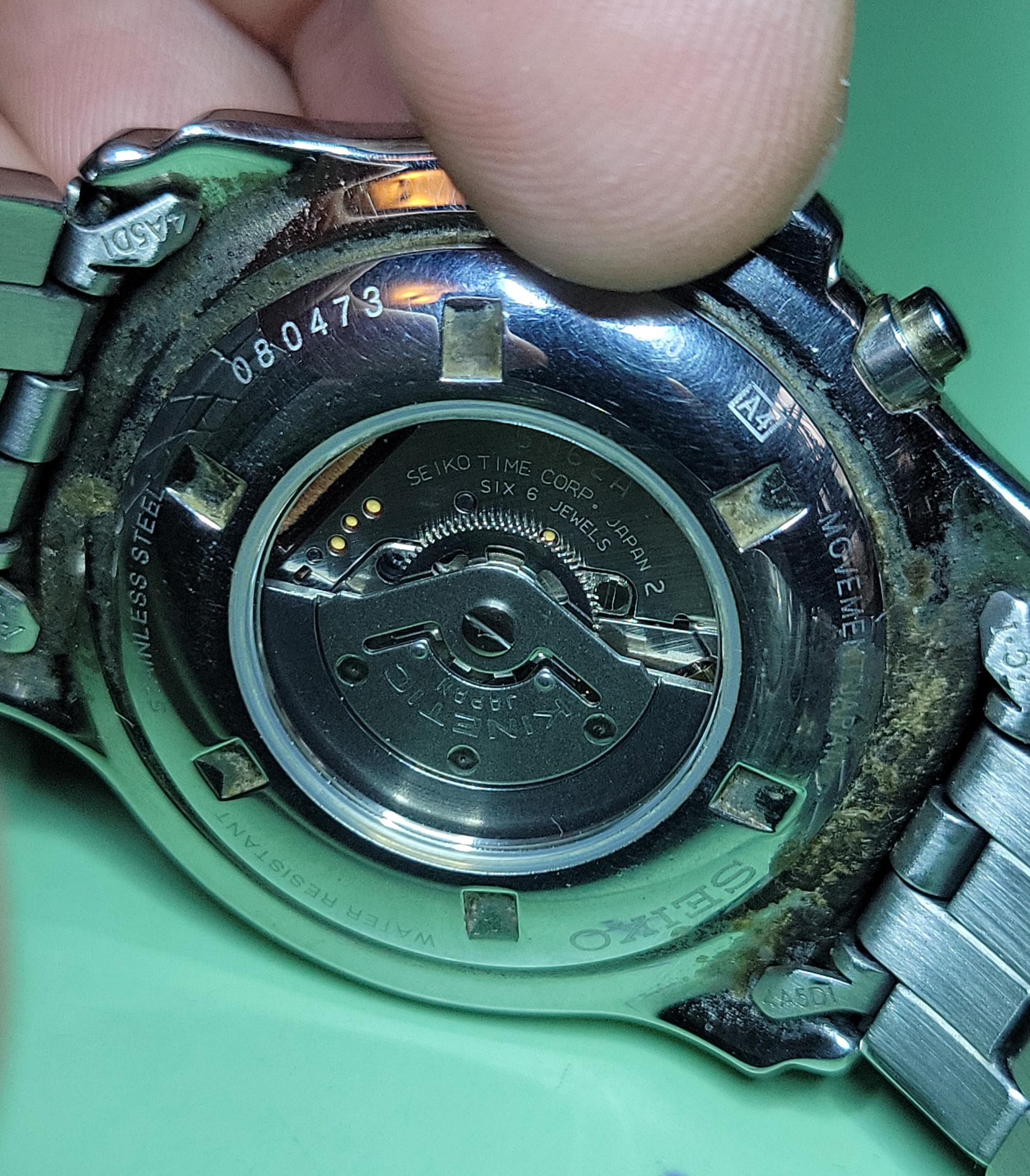
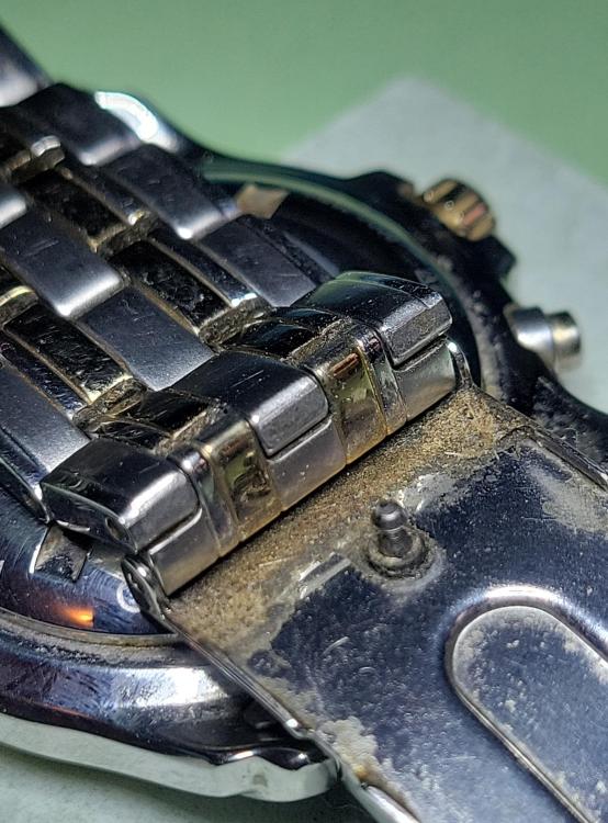
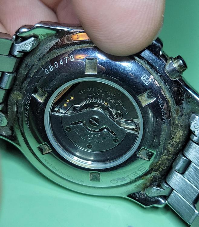
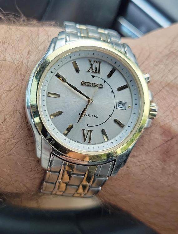
Seiko Kinetic that I picked up at a local jewelry shop on a whim. I occasionally walk in to ask if they have any broken old watches, so I like to buy a few every now and then even if they're not my favorite. After replacing the capacitor and cleaning the atrociously filthy case and bracelet, I have to say it's grown on me and I wear it a lot.
 4 points
 -
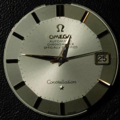
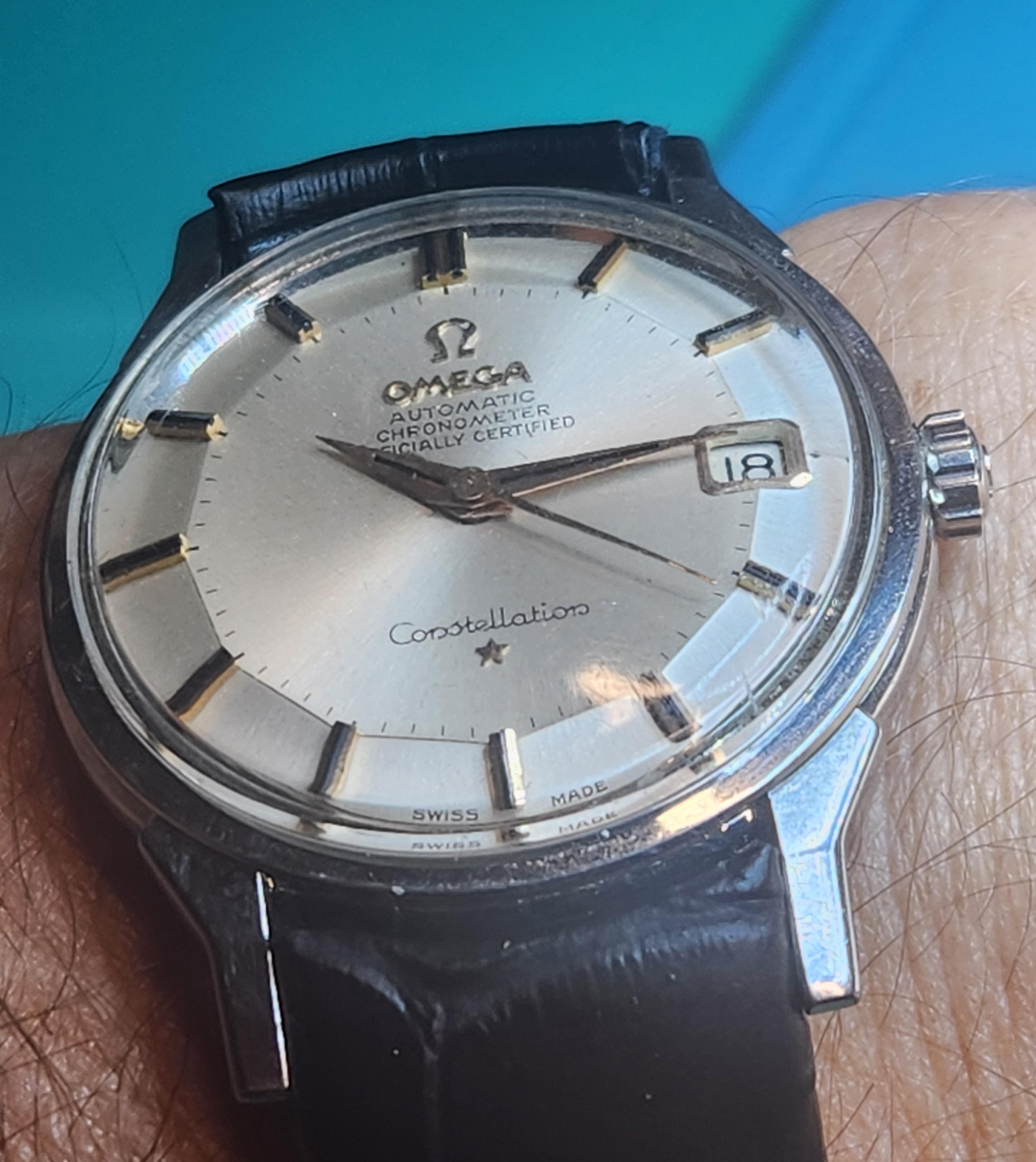
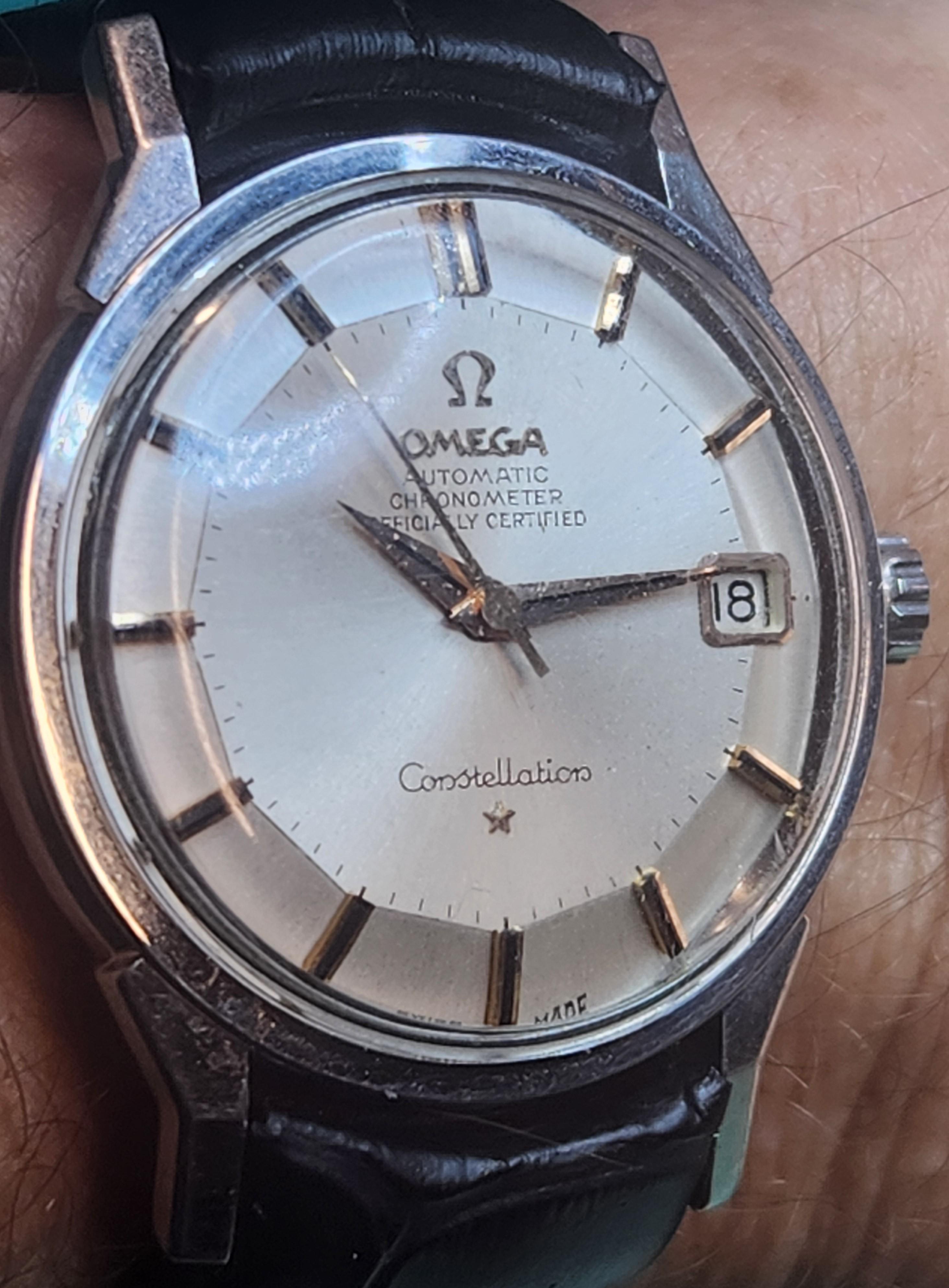
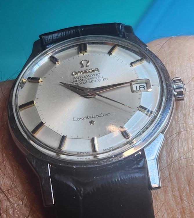
For me it is my 3 pieces from my Gramps. We all will be passing at some point and these will likely stay with me until then. Of the 3 the 1964 Omega Constellation pie pan chronometer is top pop. However I think never say never. It needs an original crystal, the small hour marker next to the date window, and a replacement strap and buckle, but otherwise nice. Here it is on a curved-end strap, not original to the design but looking to see what might be visually appealing.
 3 points
 -
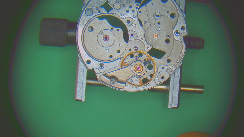
Hi Dan, I think You need to understant the main principles of watch regulation first, and then all the answers will come by themselves. No, the problem now is not the bent regulator pin. And yes, You can straighten it and just a tweezer is needed, and steady hand. What You say that You are not ready for such work is strange, this is just like a piece of wire that needs to be straightened. Yes it can break, but it will depend on how many bents/attempts it has taken previously, not by You skills. If You don't feel comfortable with it, just leave it alone, as I said the problem is not there. There is a thing - You complain about faster rate, but we don't see on You pictures regulator in end of it's movement to the '-'. This makes me suggess that in this position the things get even worse, am I right? If I am right, this will confirm that the problem is in hairspring end shape. What You need to do is to work on the hairspring terminal curve in a manner that will make hairspring to stay concentric and not change it's position when regulator is moved. Turn the cock with the balance up and move the regulator to the max in '-' direction. I mean the physical end of the motion, not the marks on the scale for example. You will see that the spring is pressed then and out of concentricity. Do no warry, just use a needle to press the end that comes out of the regulator in order to bend it a little so the pressure on the spring is released and it will position concentrically. After it is done, press the spring right where it is out of the stud in order to bend it a little so it will not be prssed firmly to none of the regulator pins, and if it changes the spring position, repeat the first part. Then start to move the regulator to '+' and observe the spring. If it changes it's position out of consentricity, then use the needle to press nere where the spring goes out of the regulator pins in order to bend it to direction needed to recover concenricity. When it is done to the end of the movement of the regulator to '+' return it back to the end of '-', see if something changed and correct it again. What You need to acheave is the hairspring to be not touching anything, not only in neutral position of the balance, but in all positions of it's movement. To observe it , You will need to dissassemble the movement and put in place only the balance wit it's cock, then slowly rotate the balance wheel while observing the spring.3 points
-
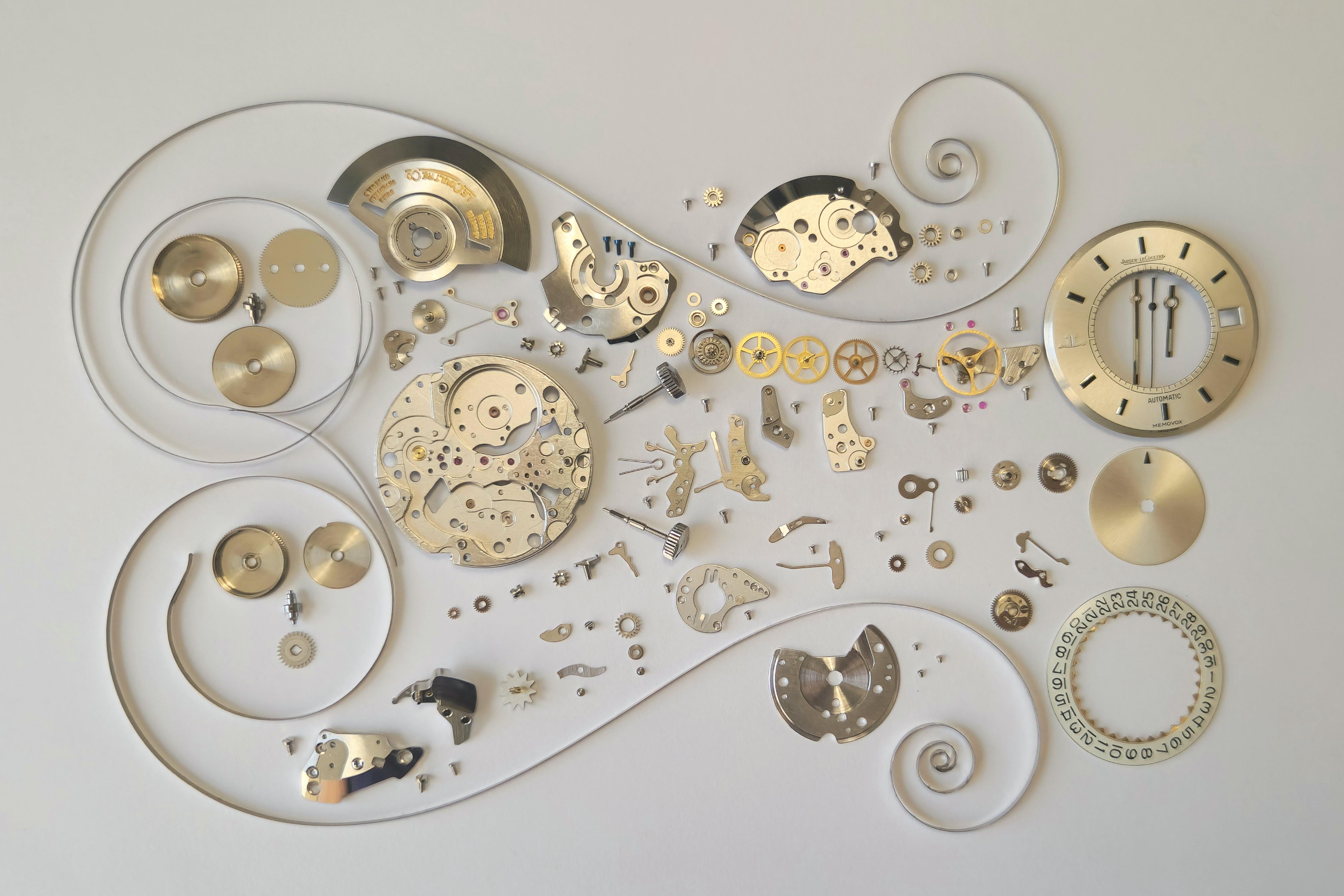
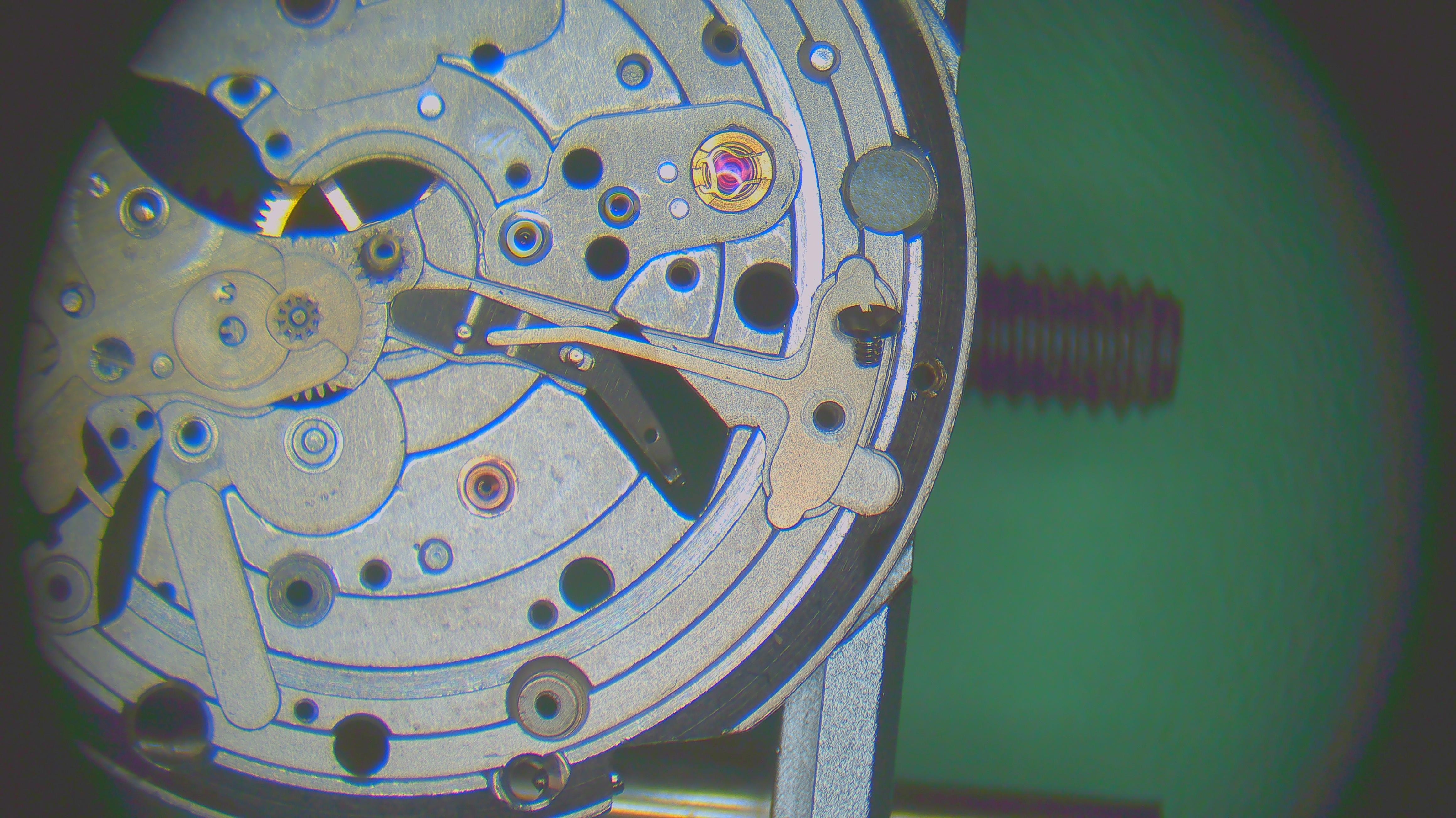
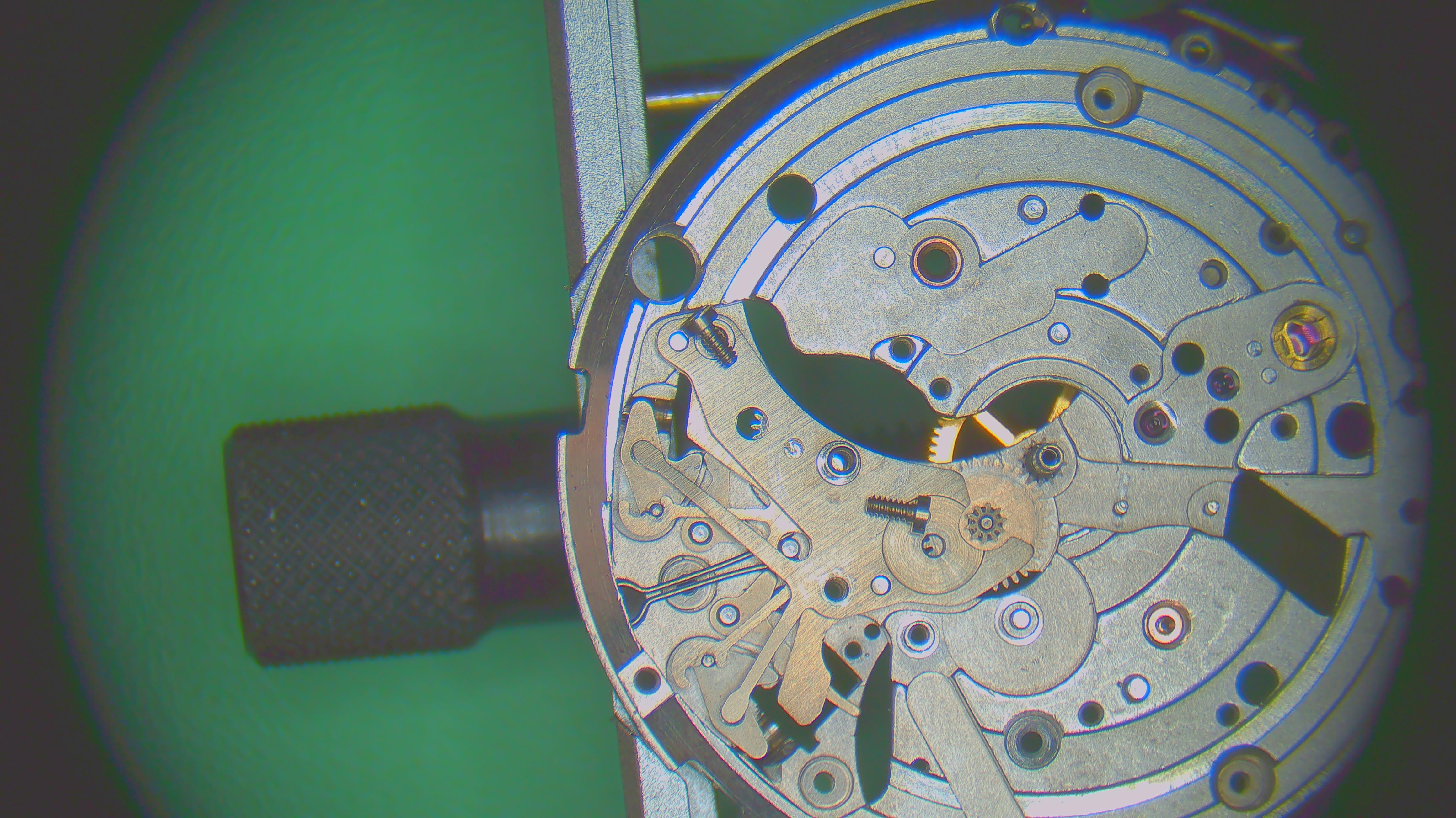
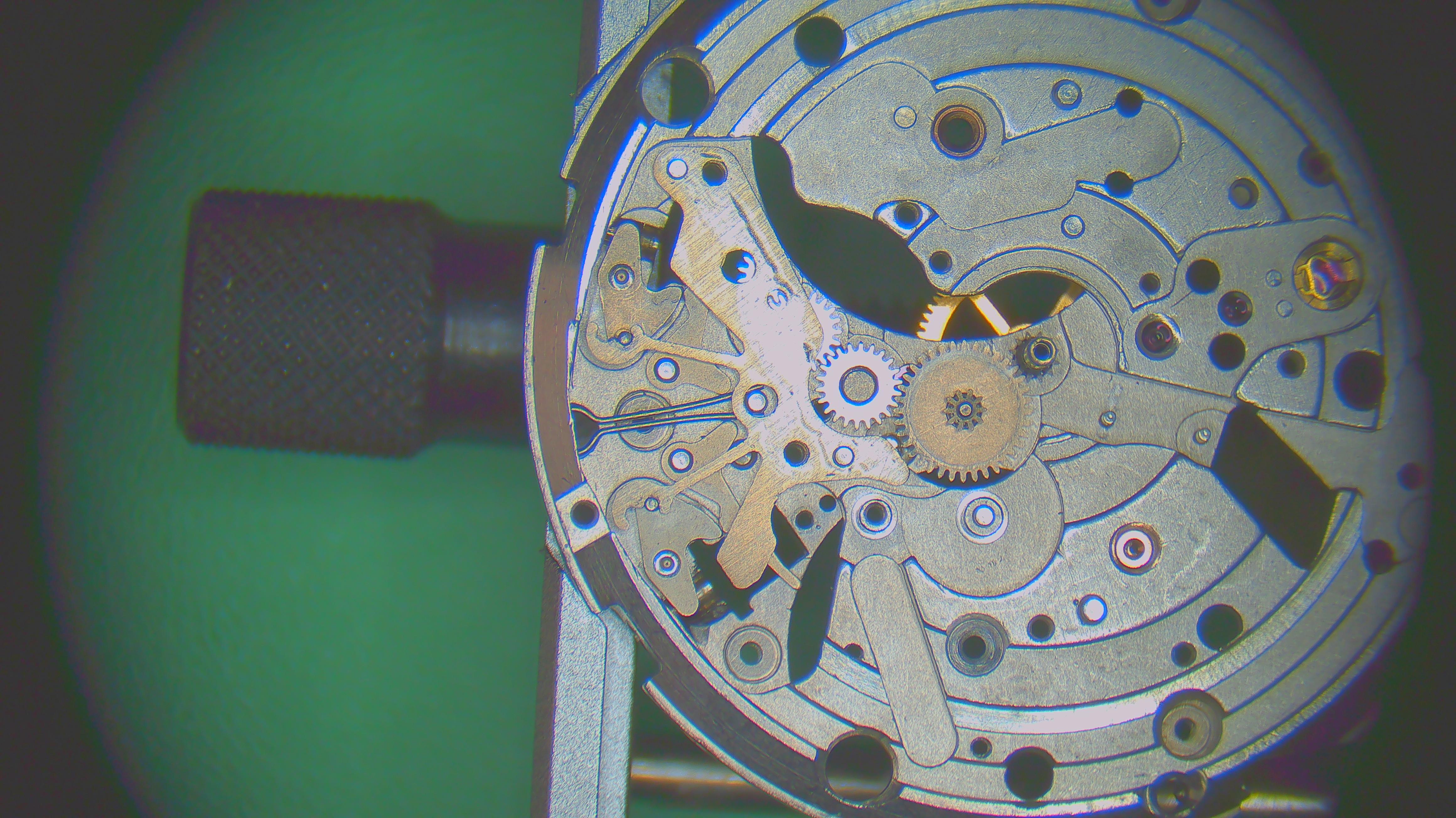
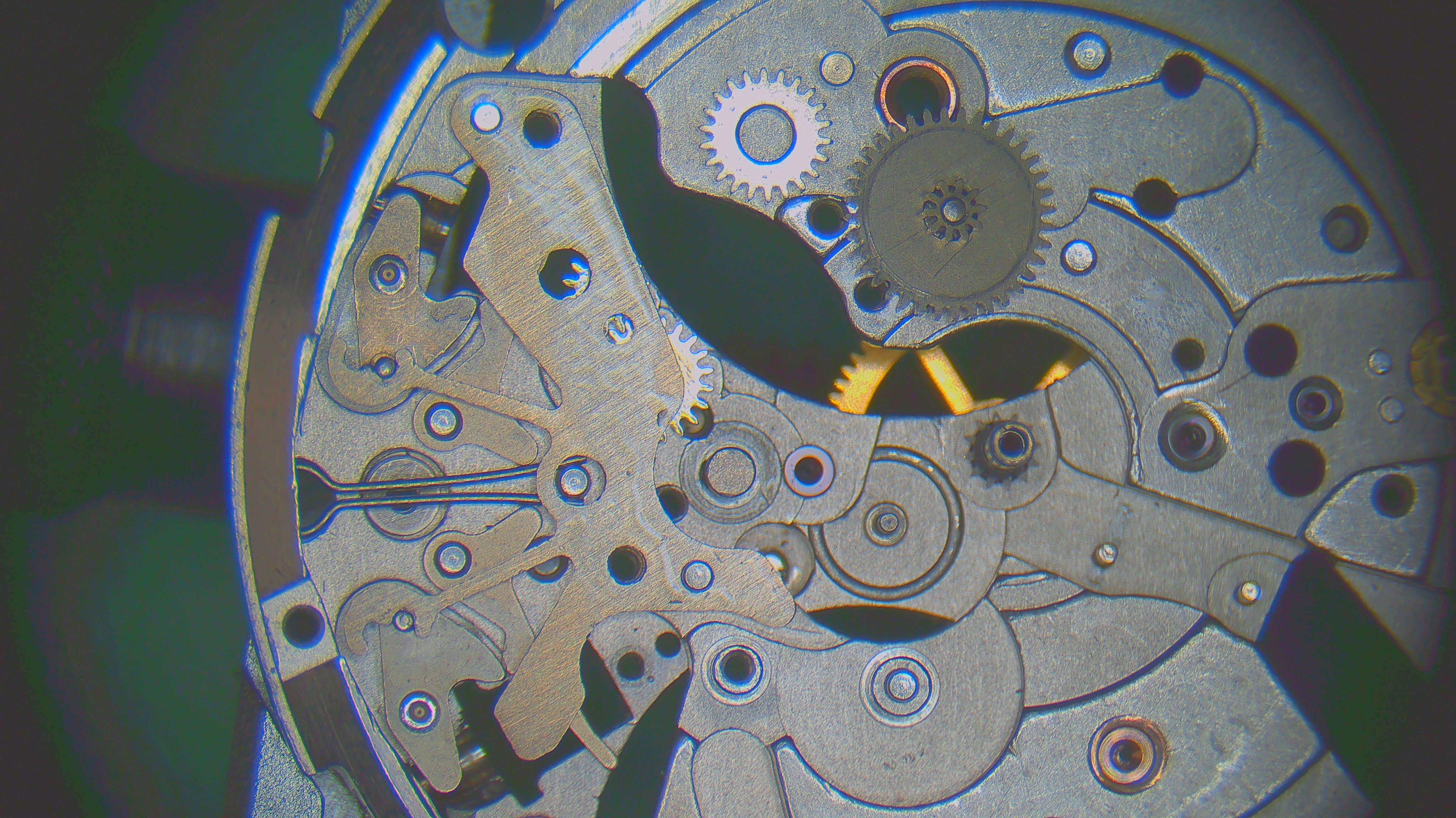
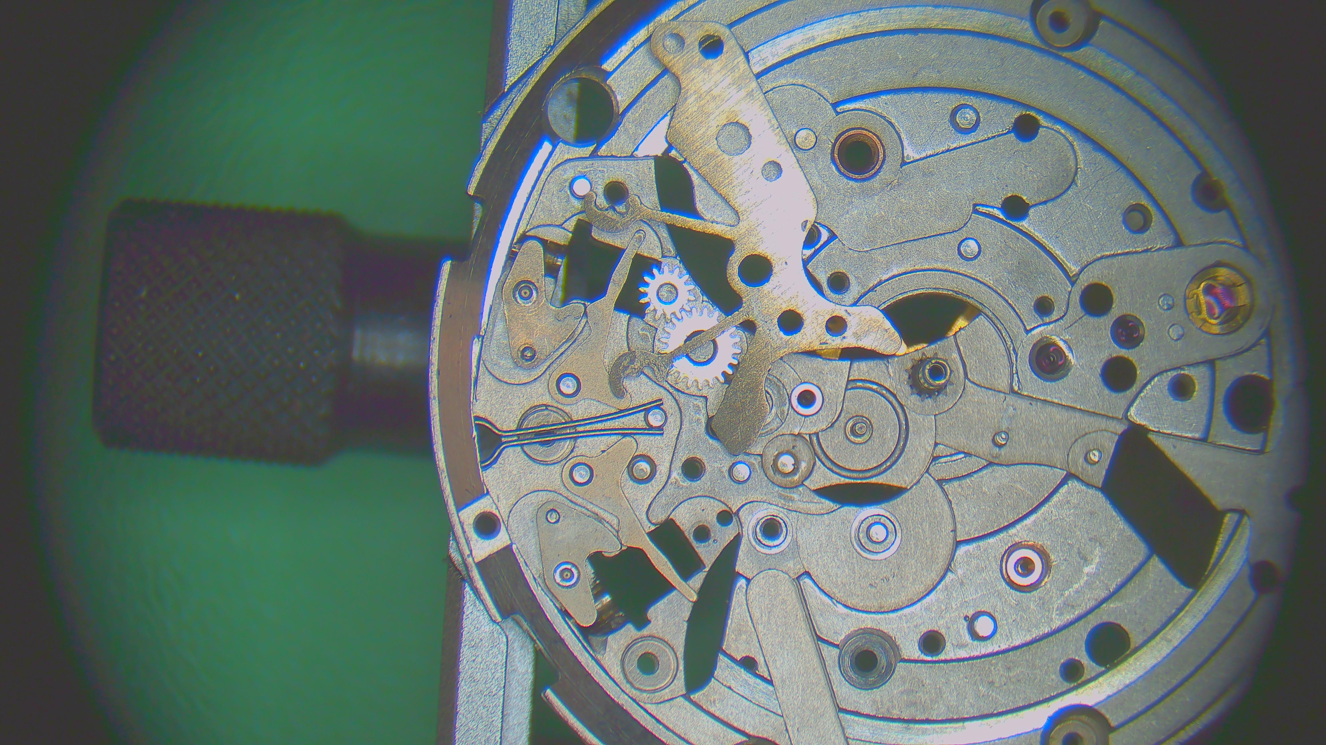
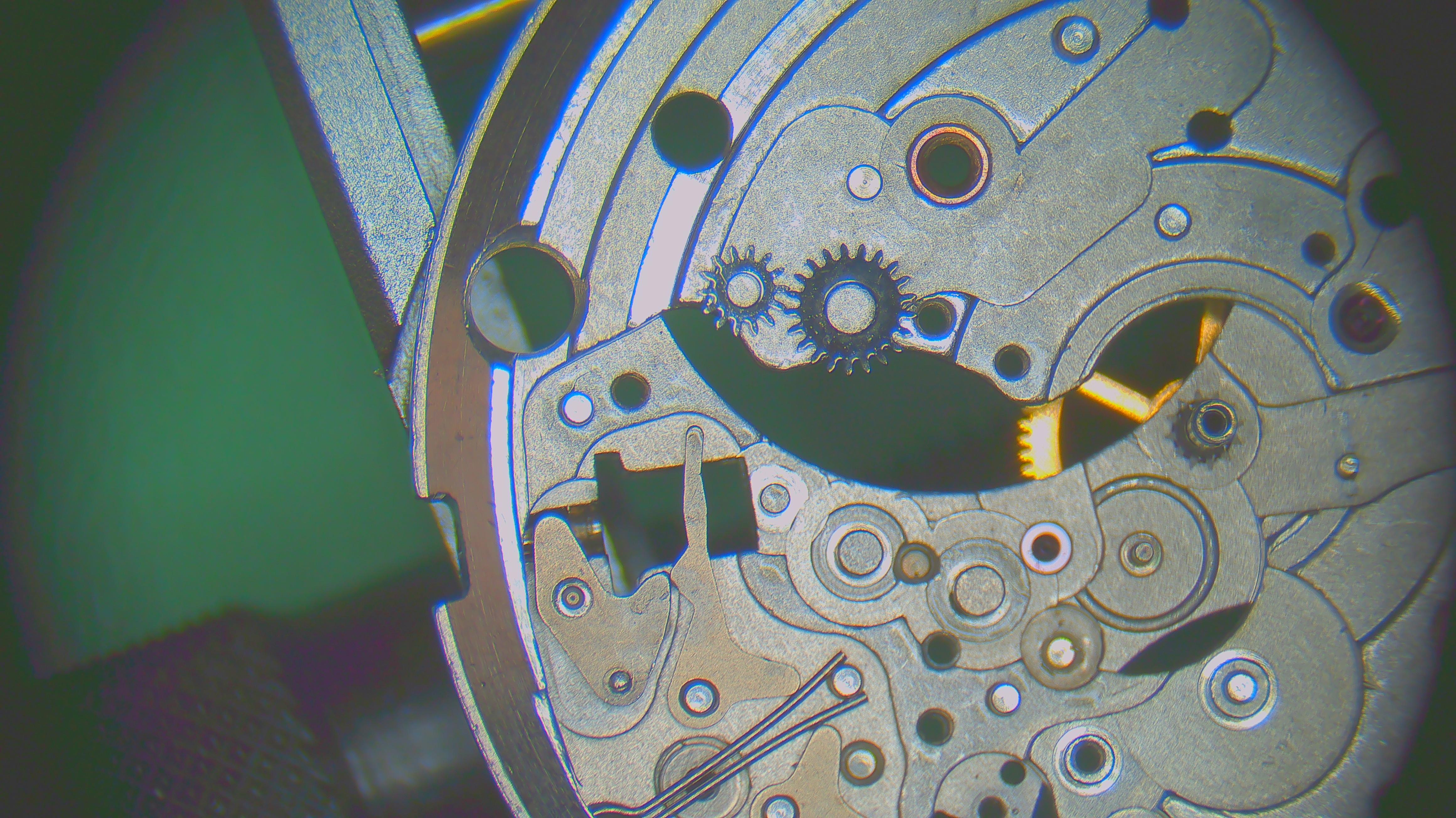
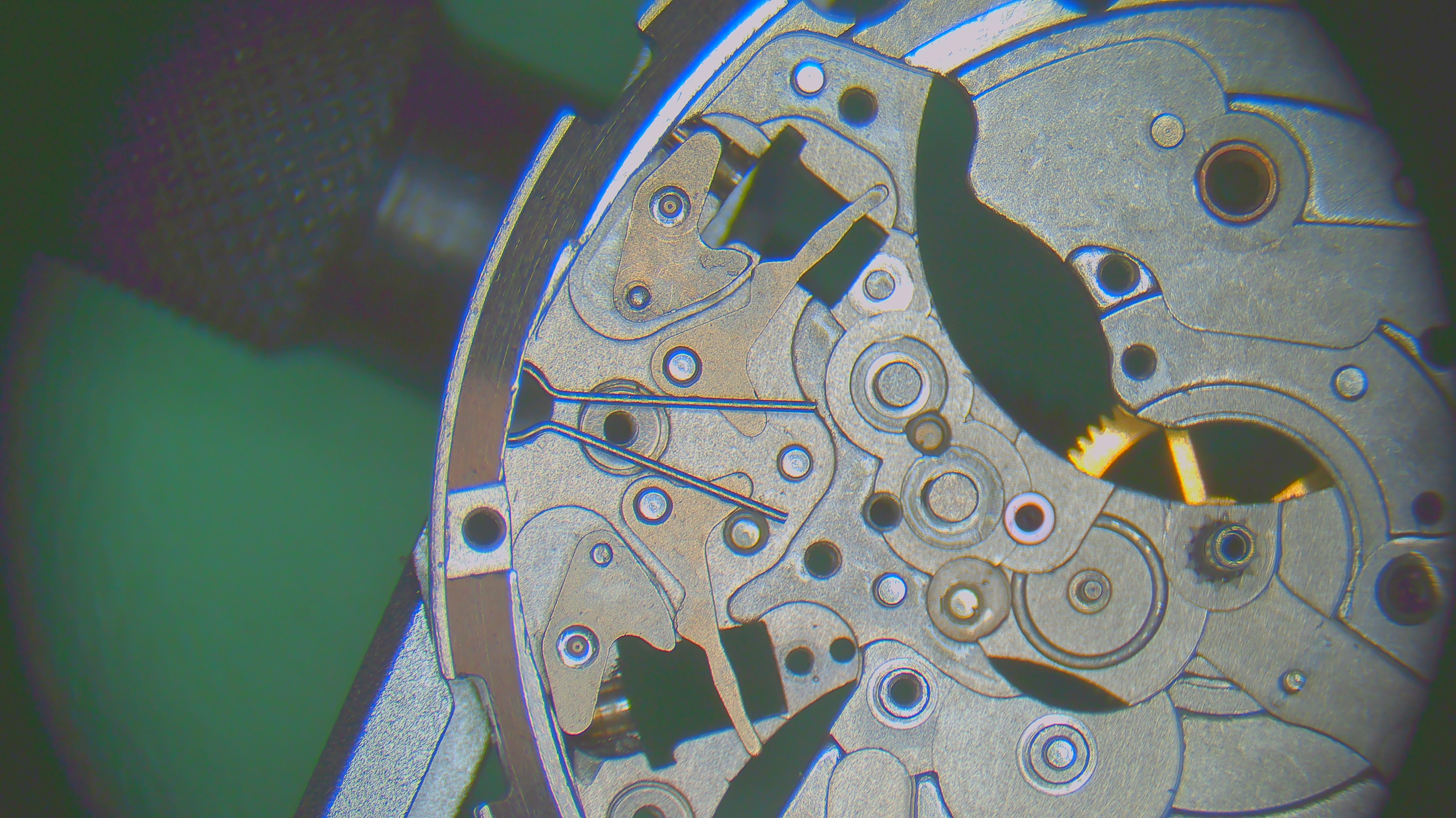
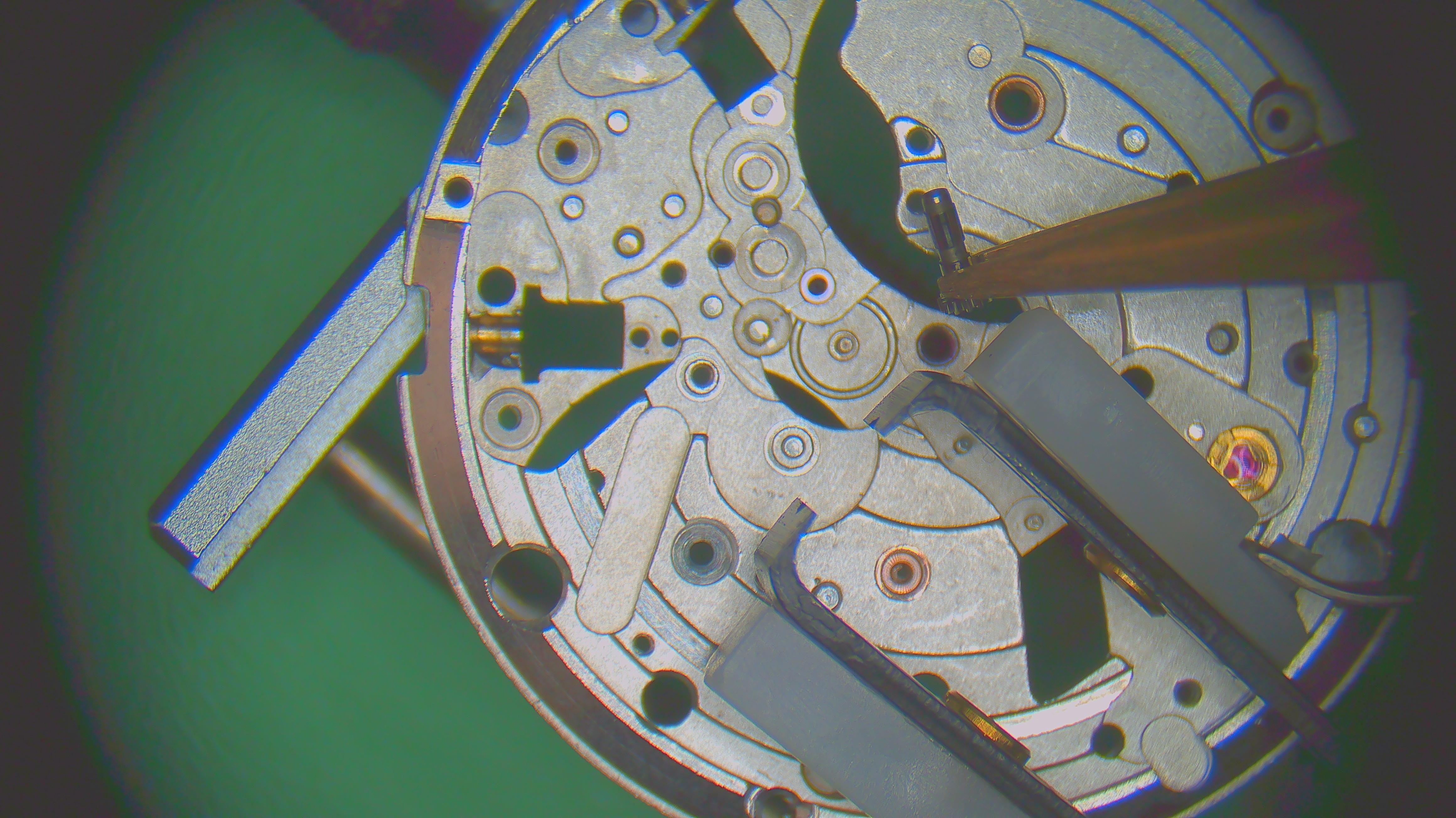
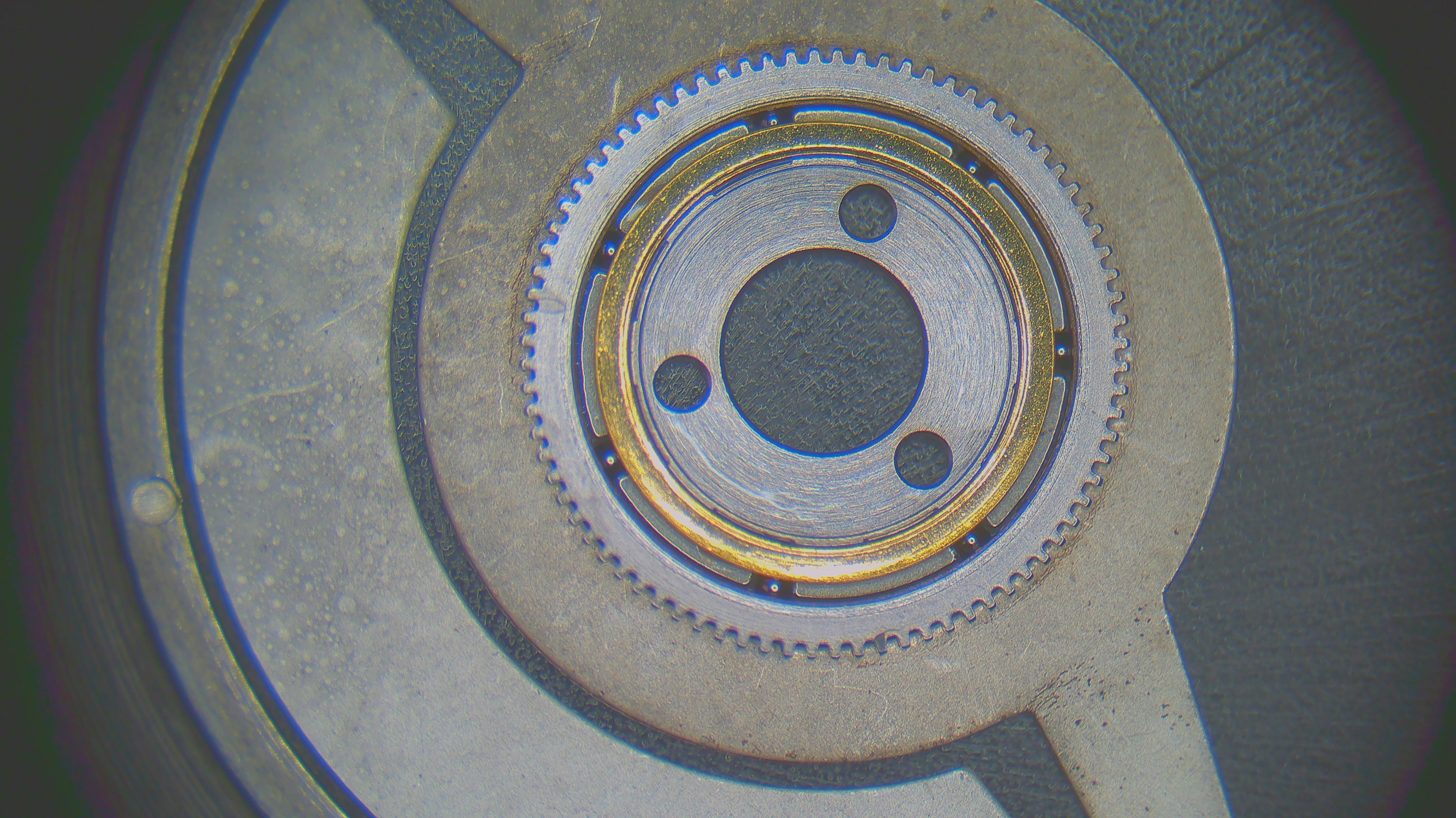
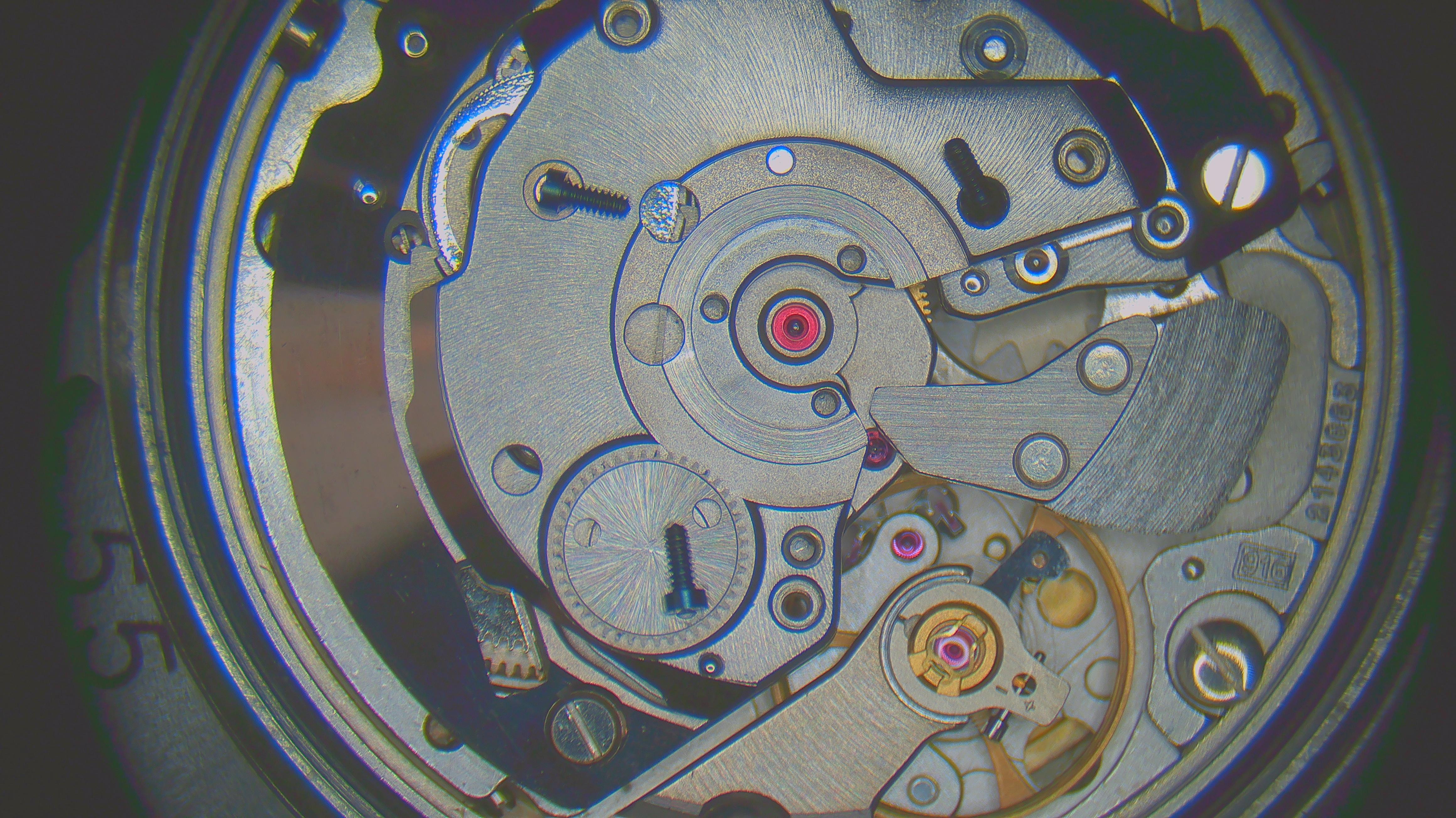
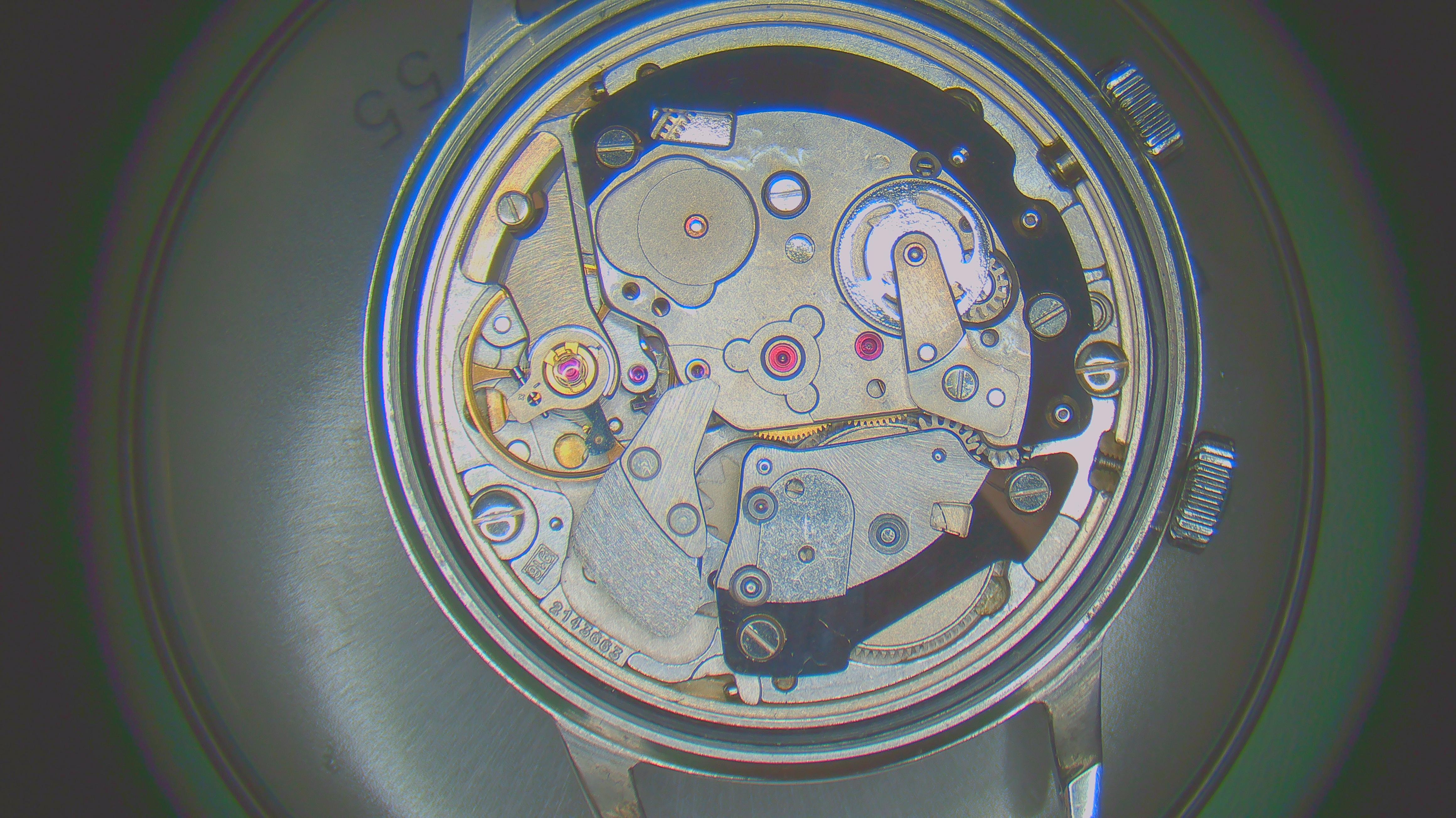
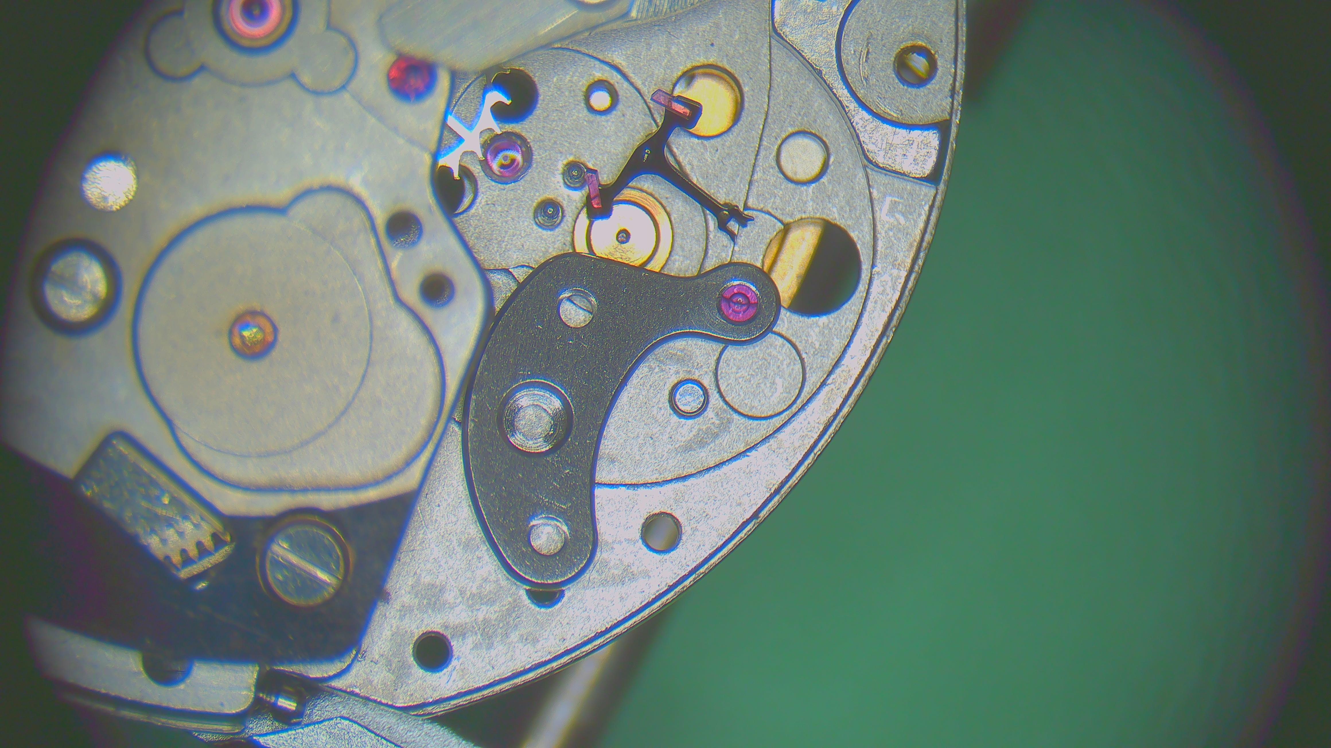
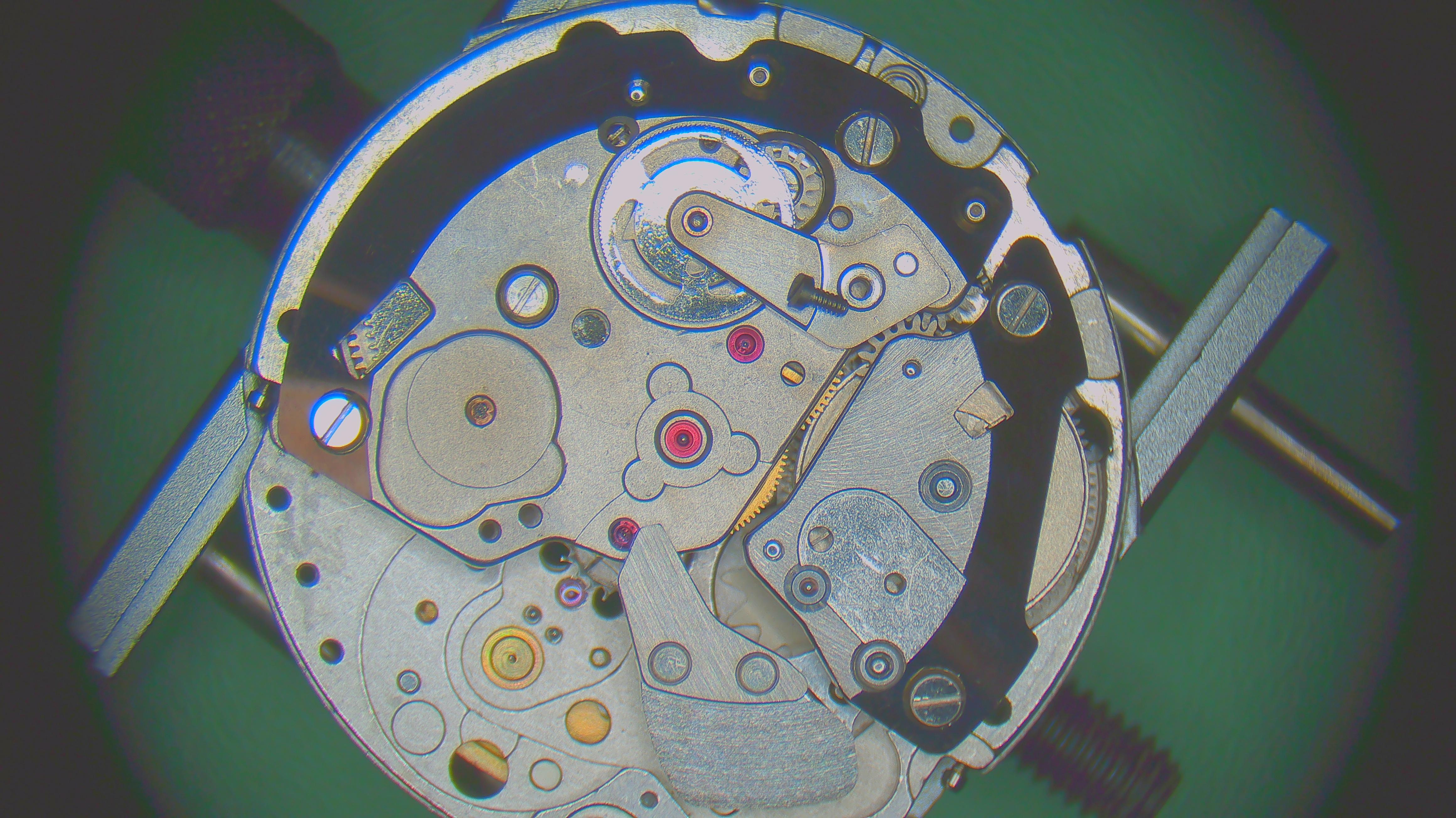
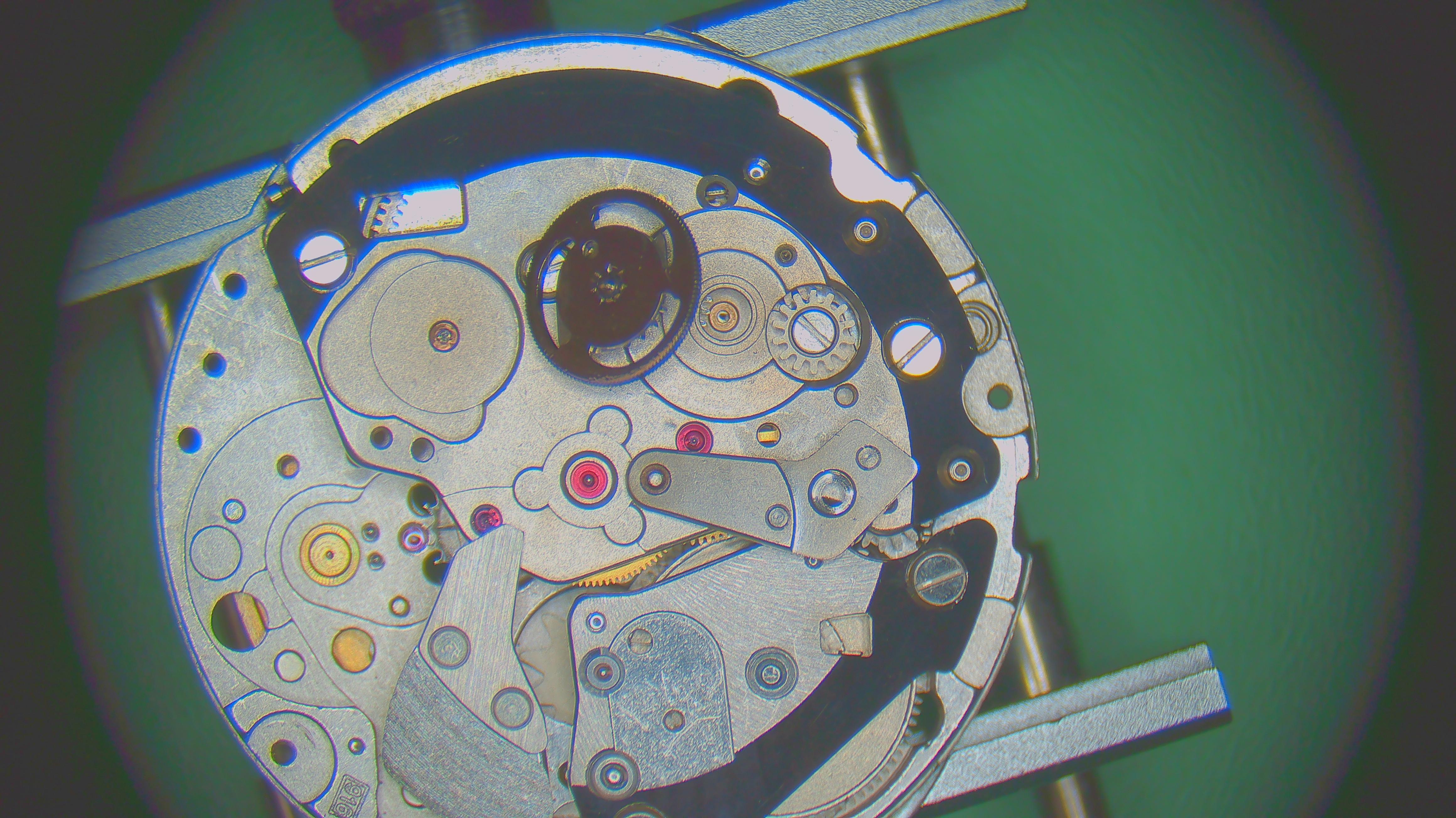
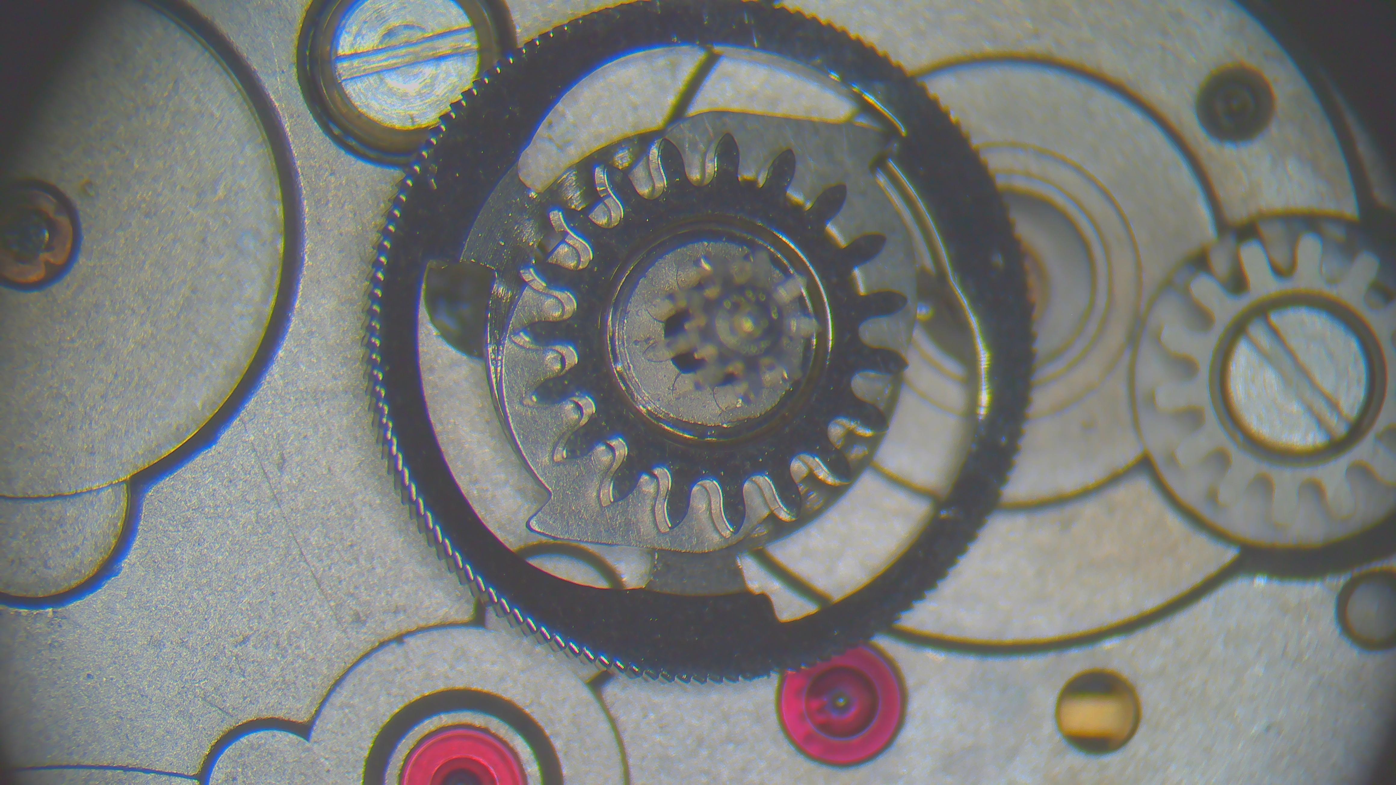
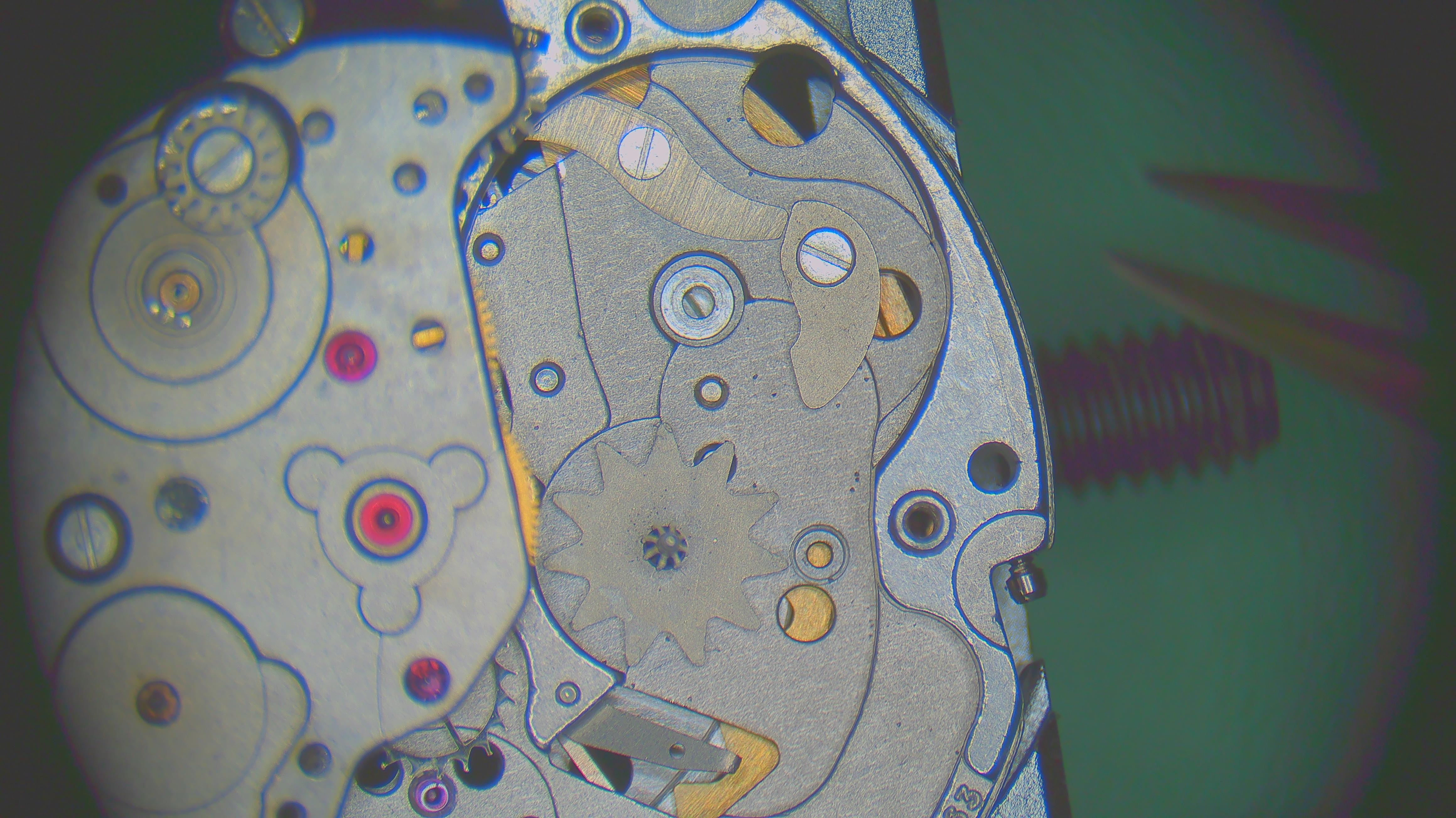
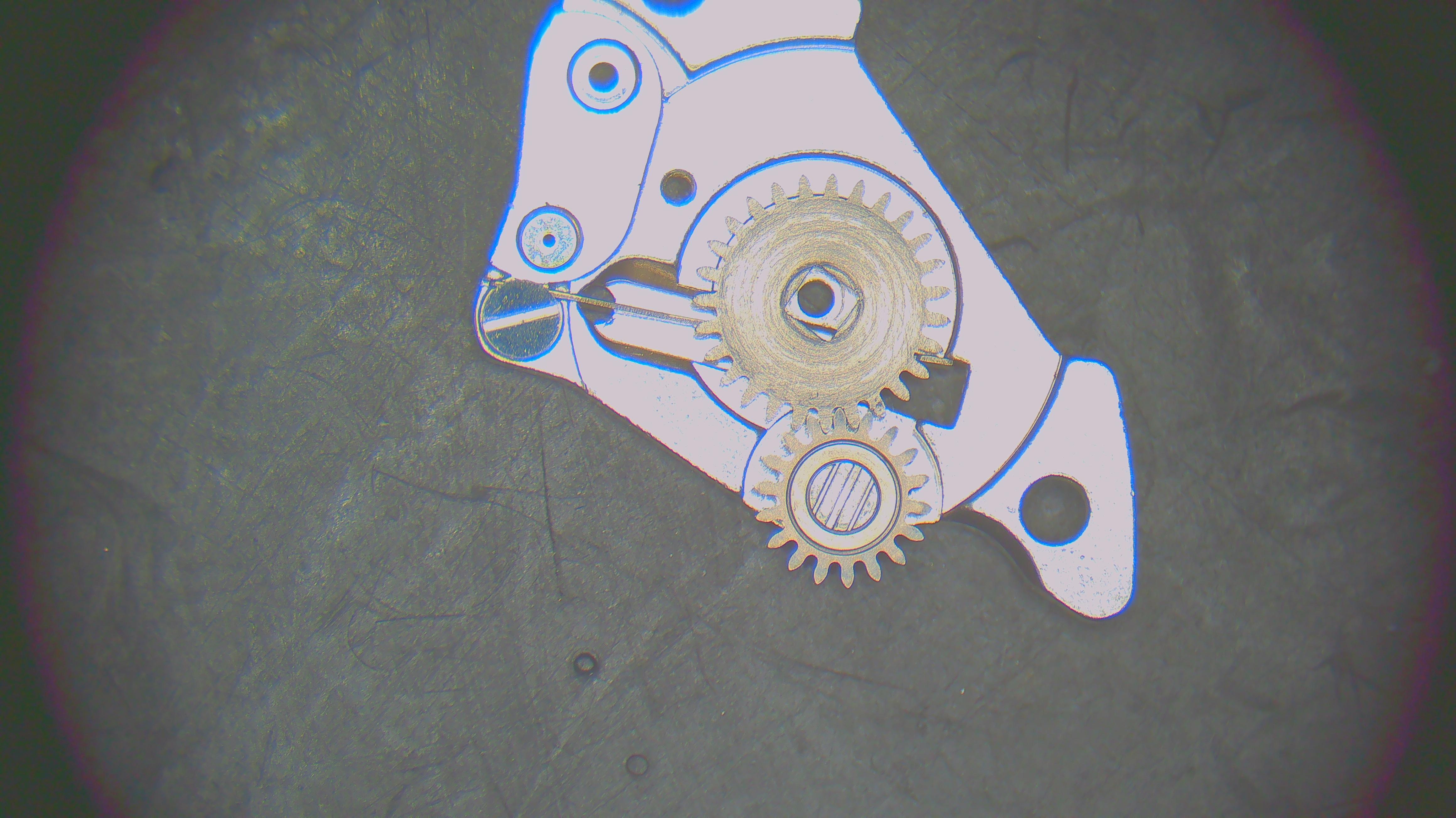
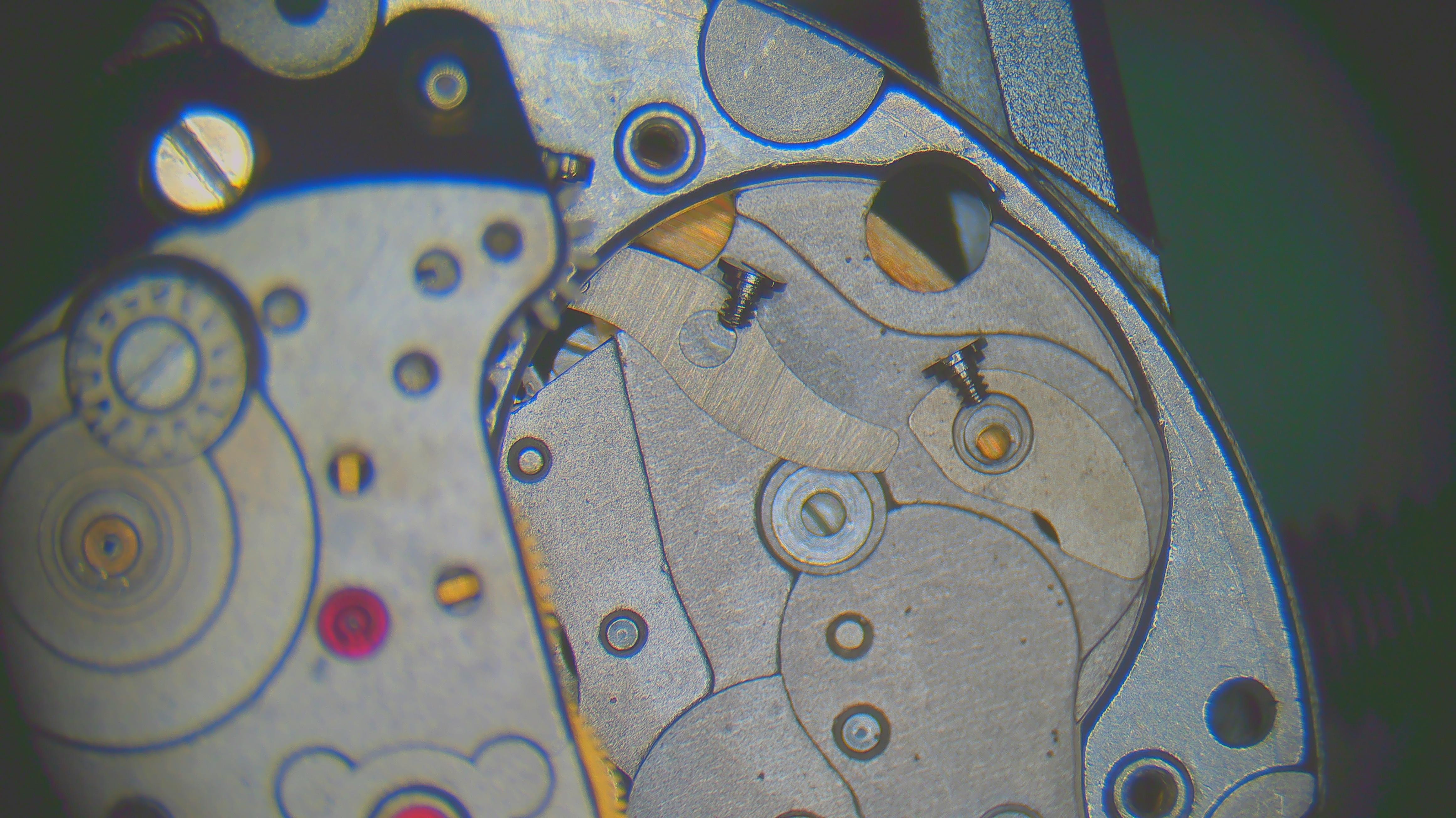
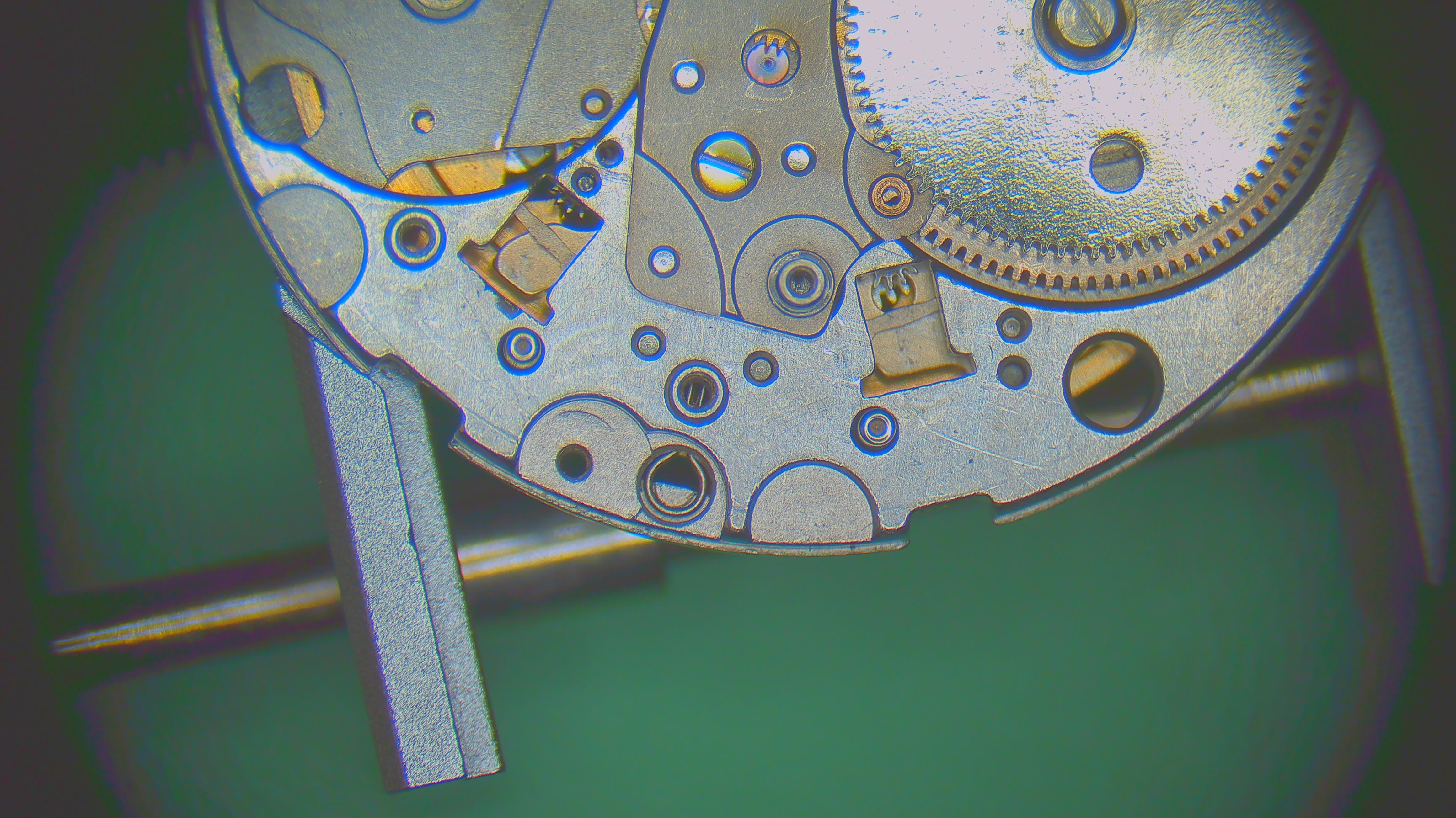
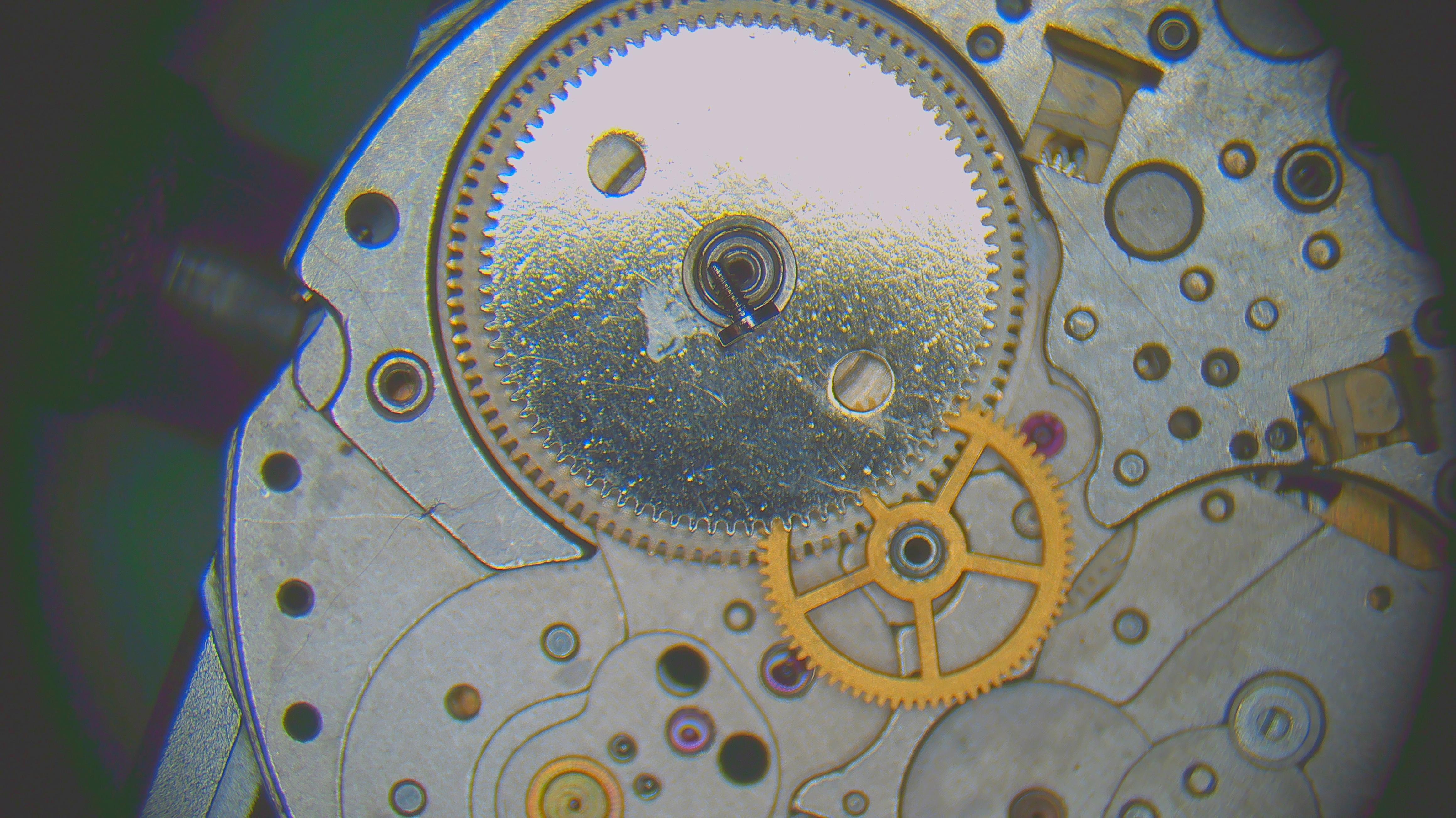
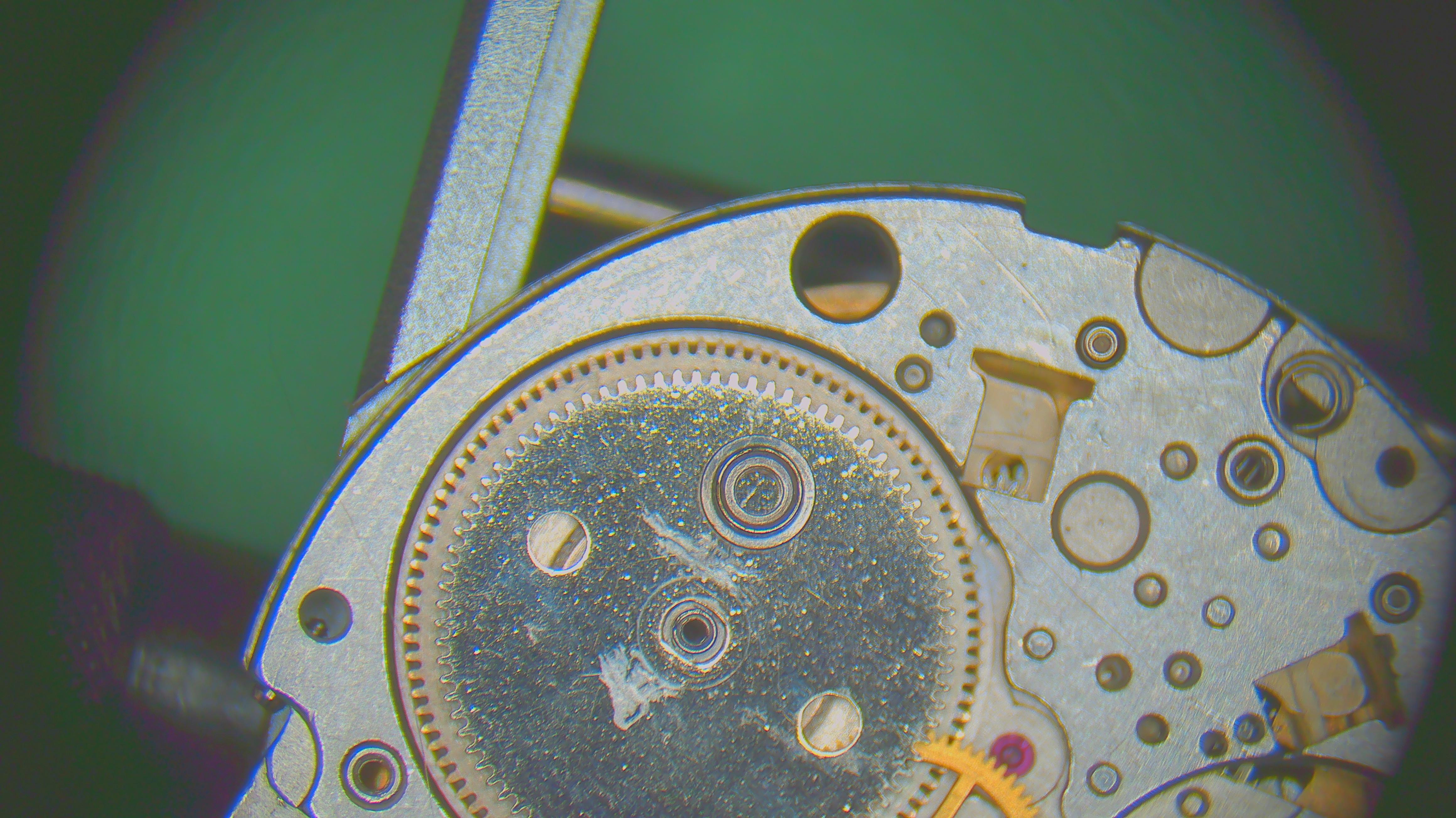
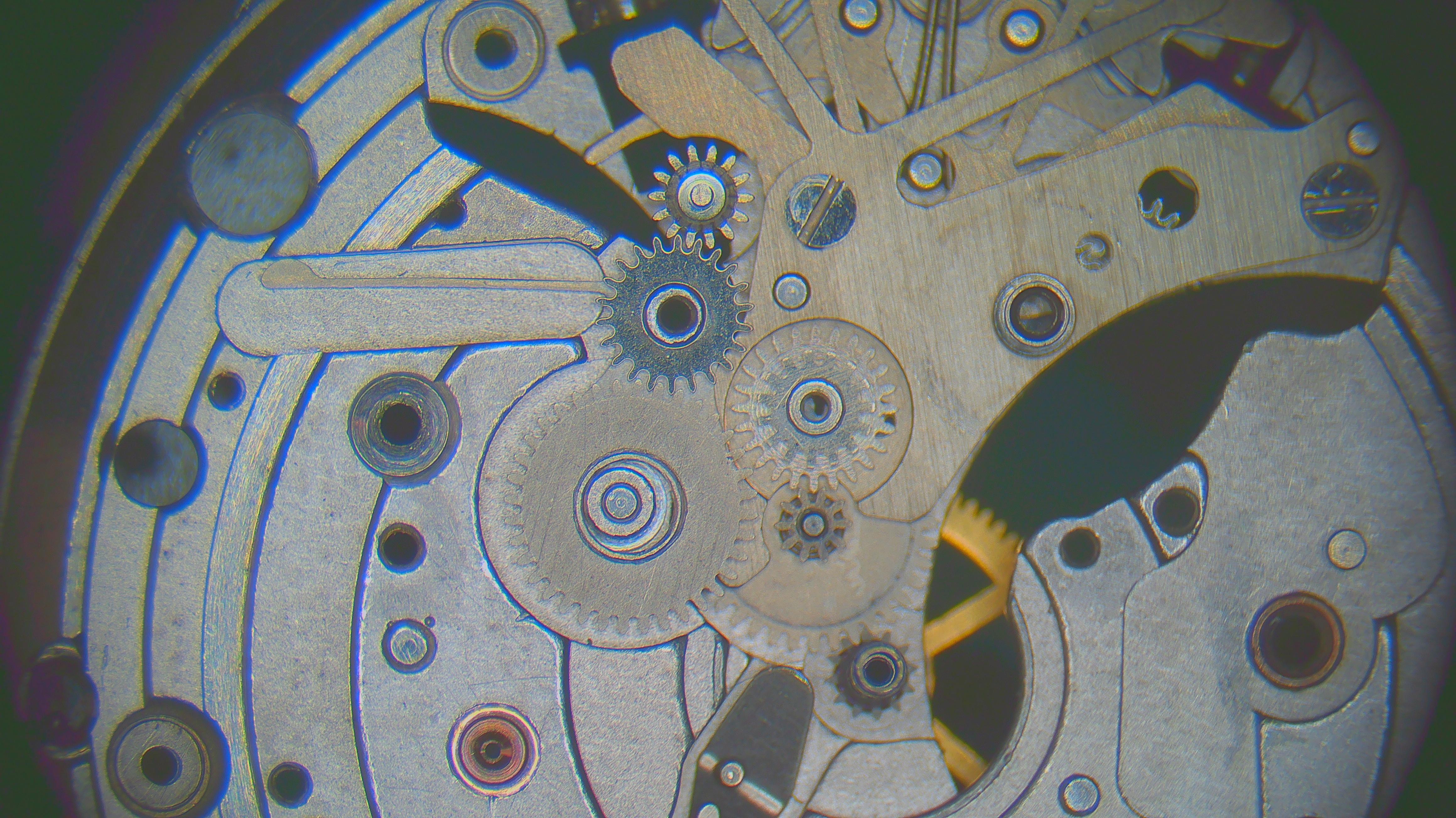
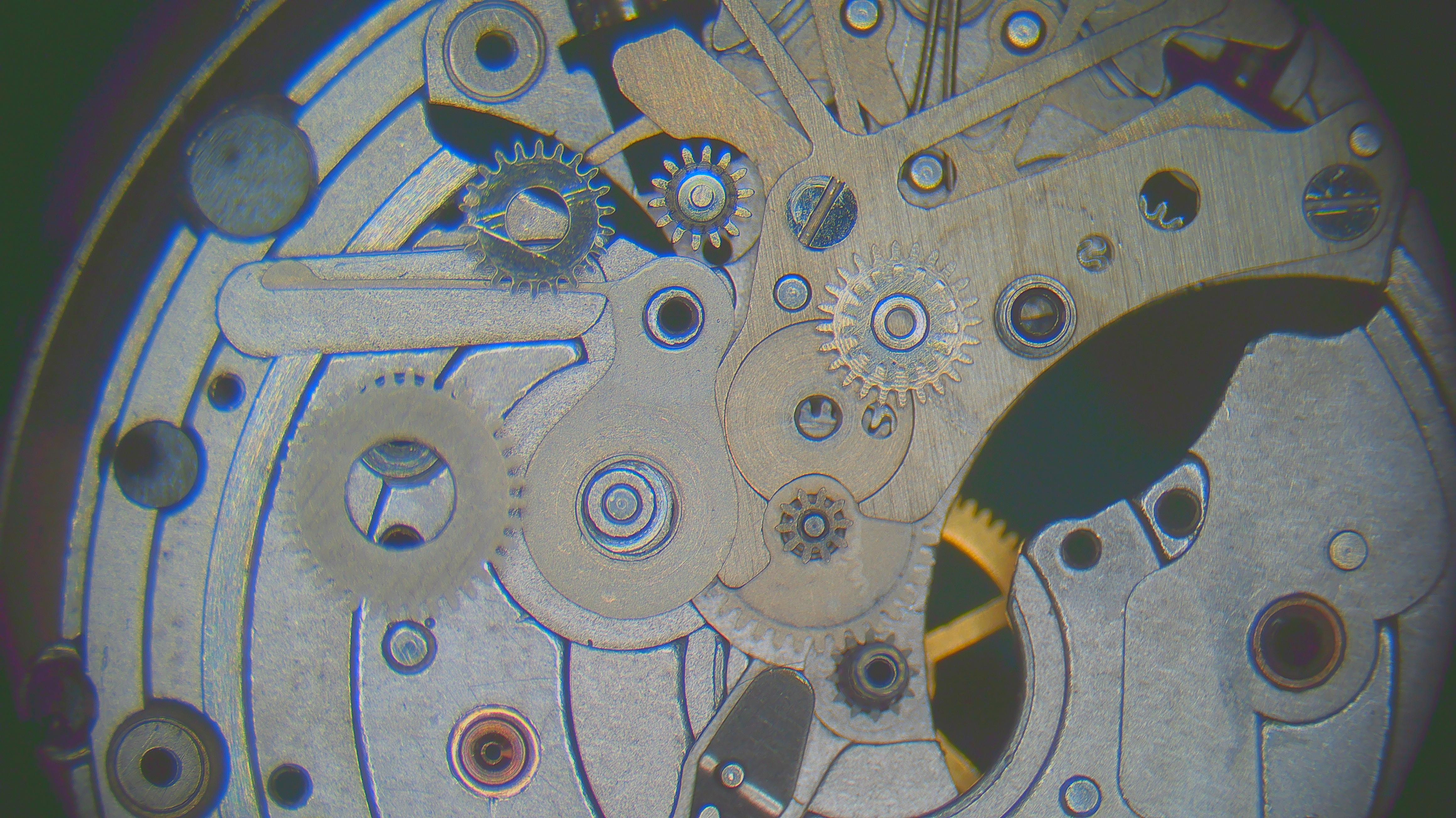
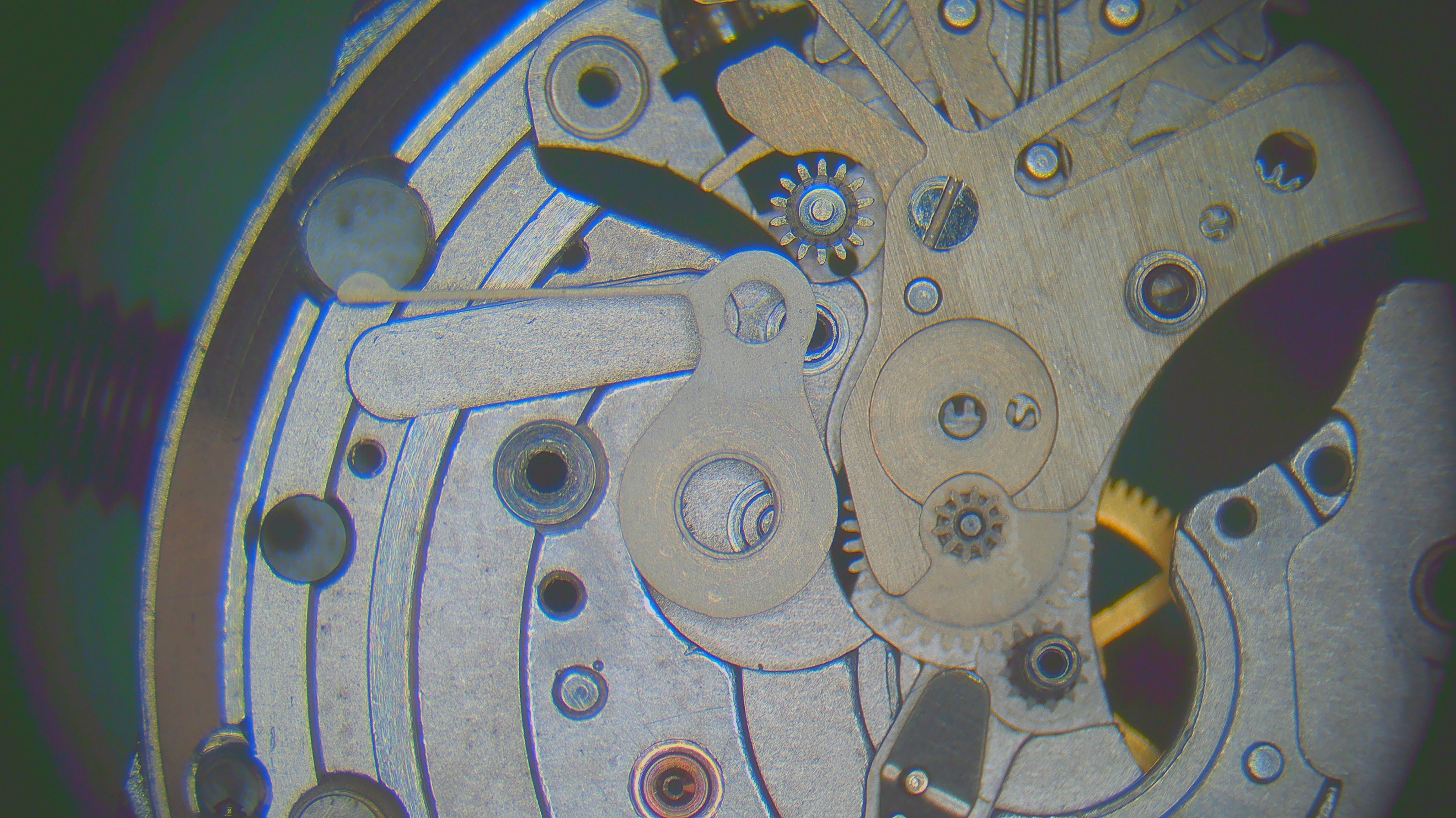
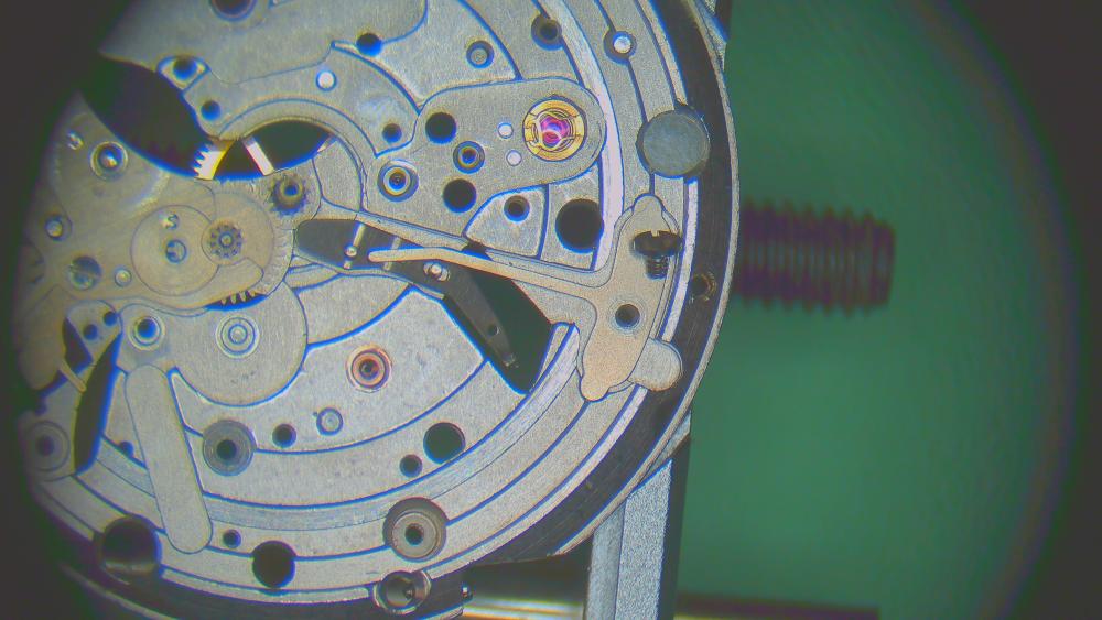
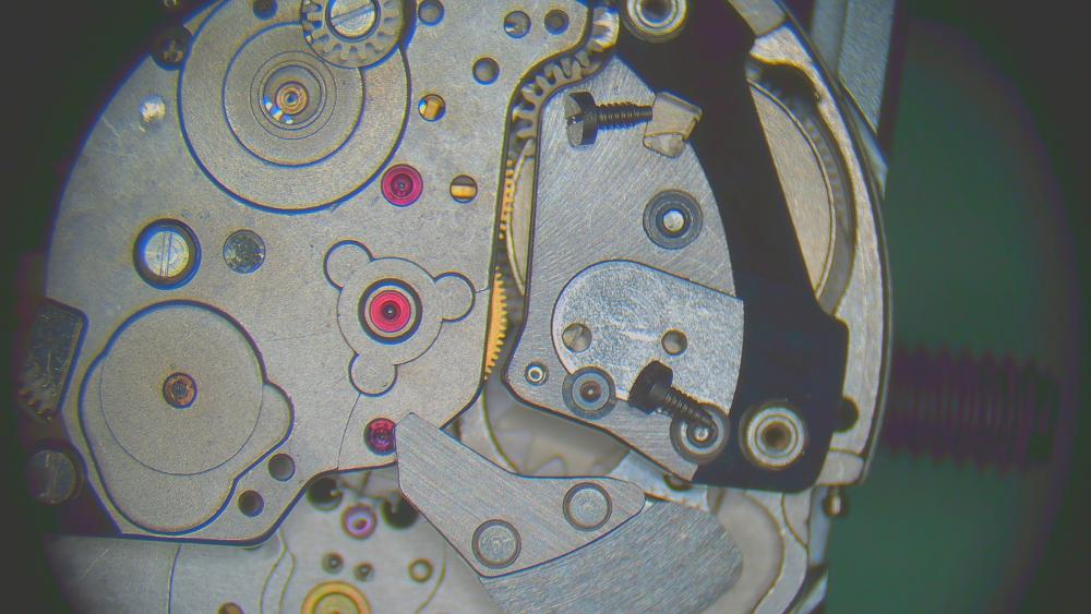
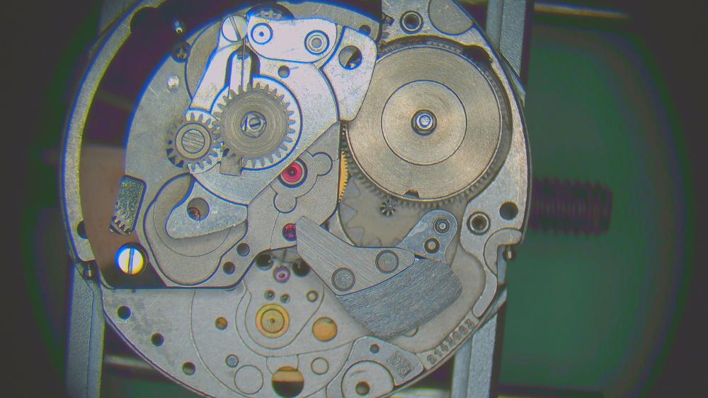
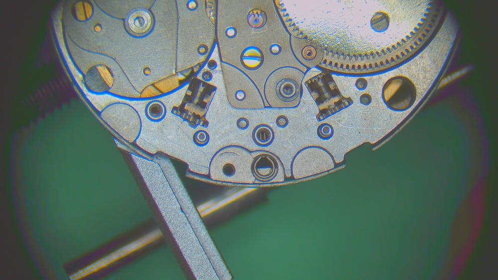
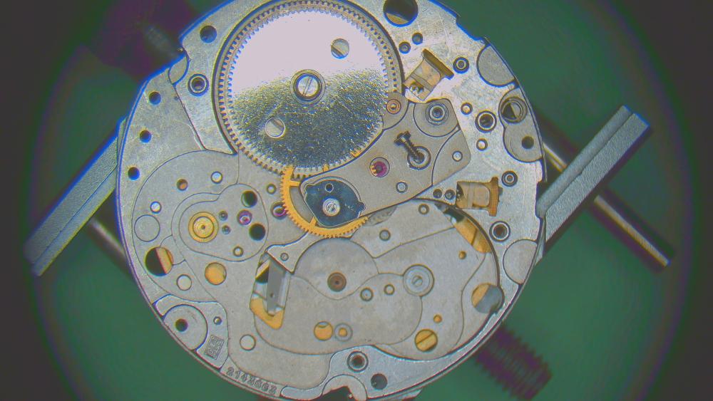
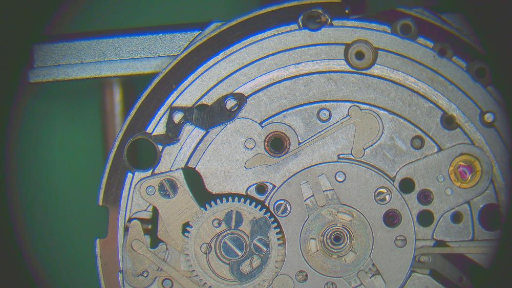
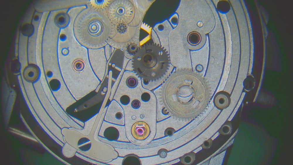
After cleaning, here's my usual "movement art" picture. Assembly coming later..
 3 points
 -
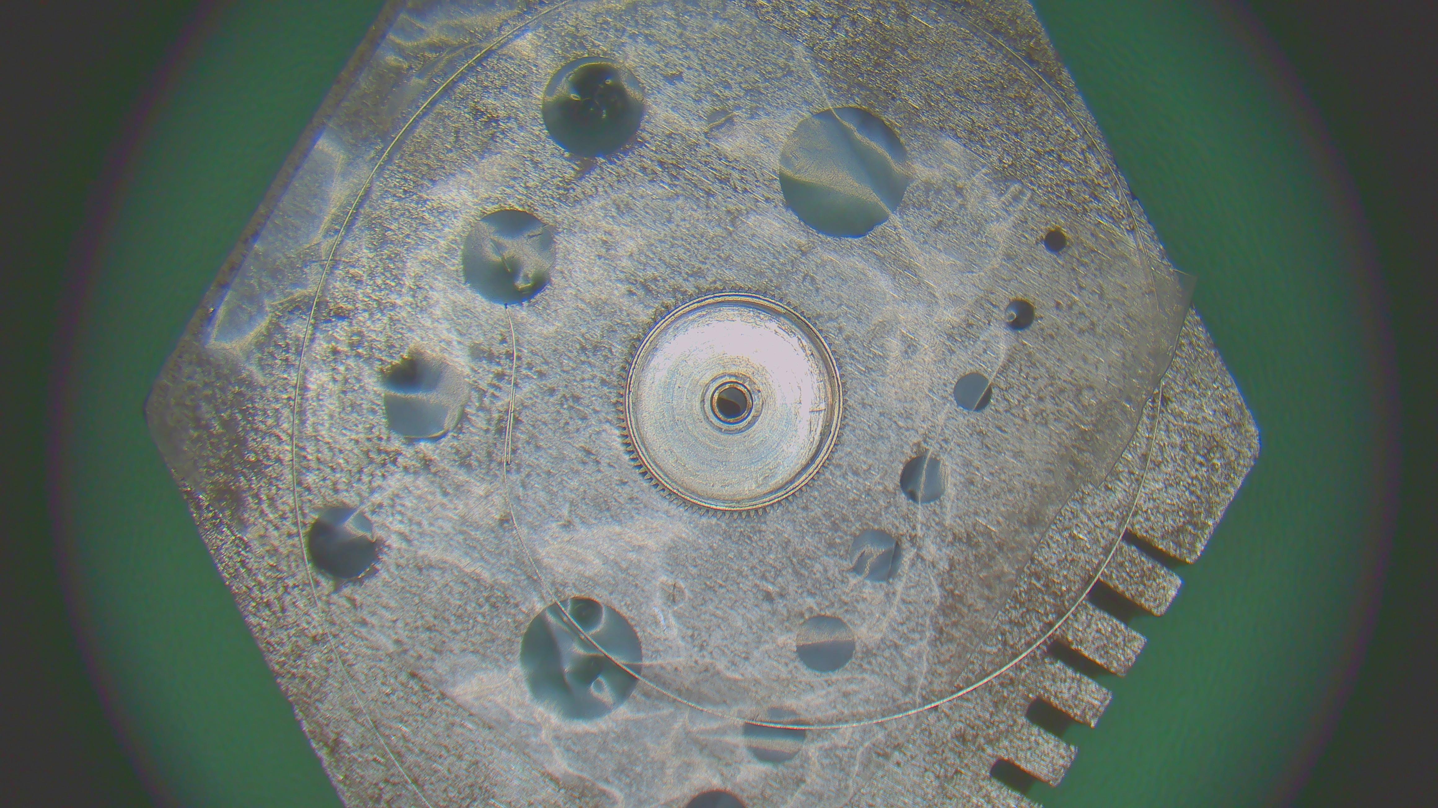
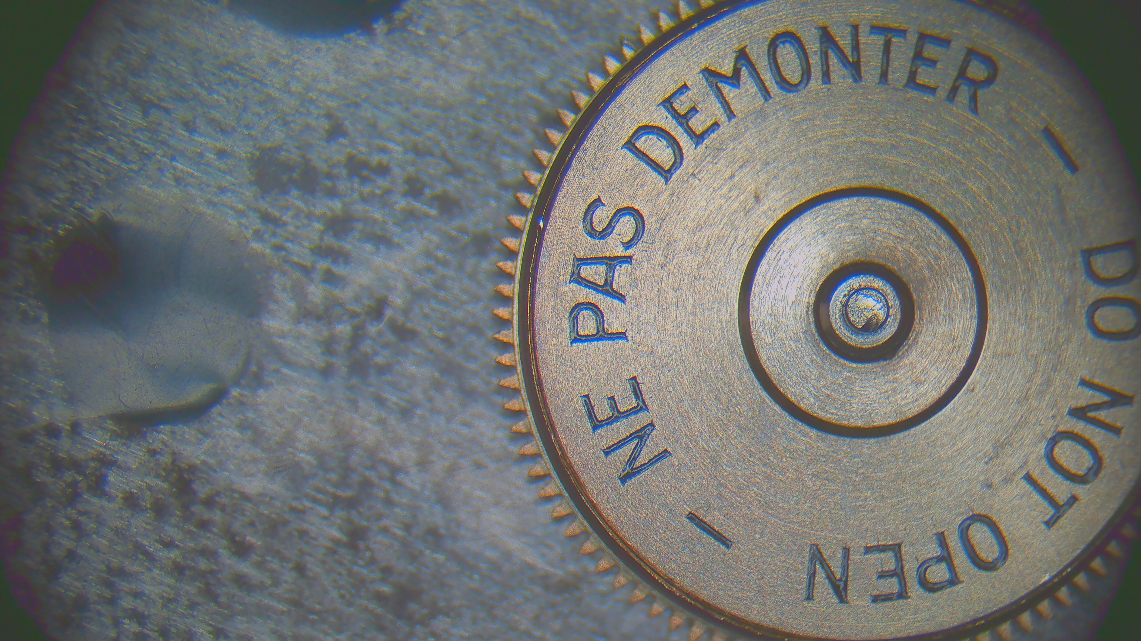
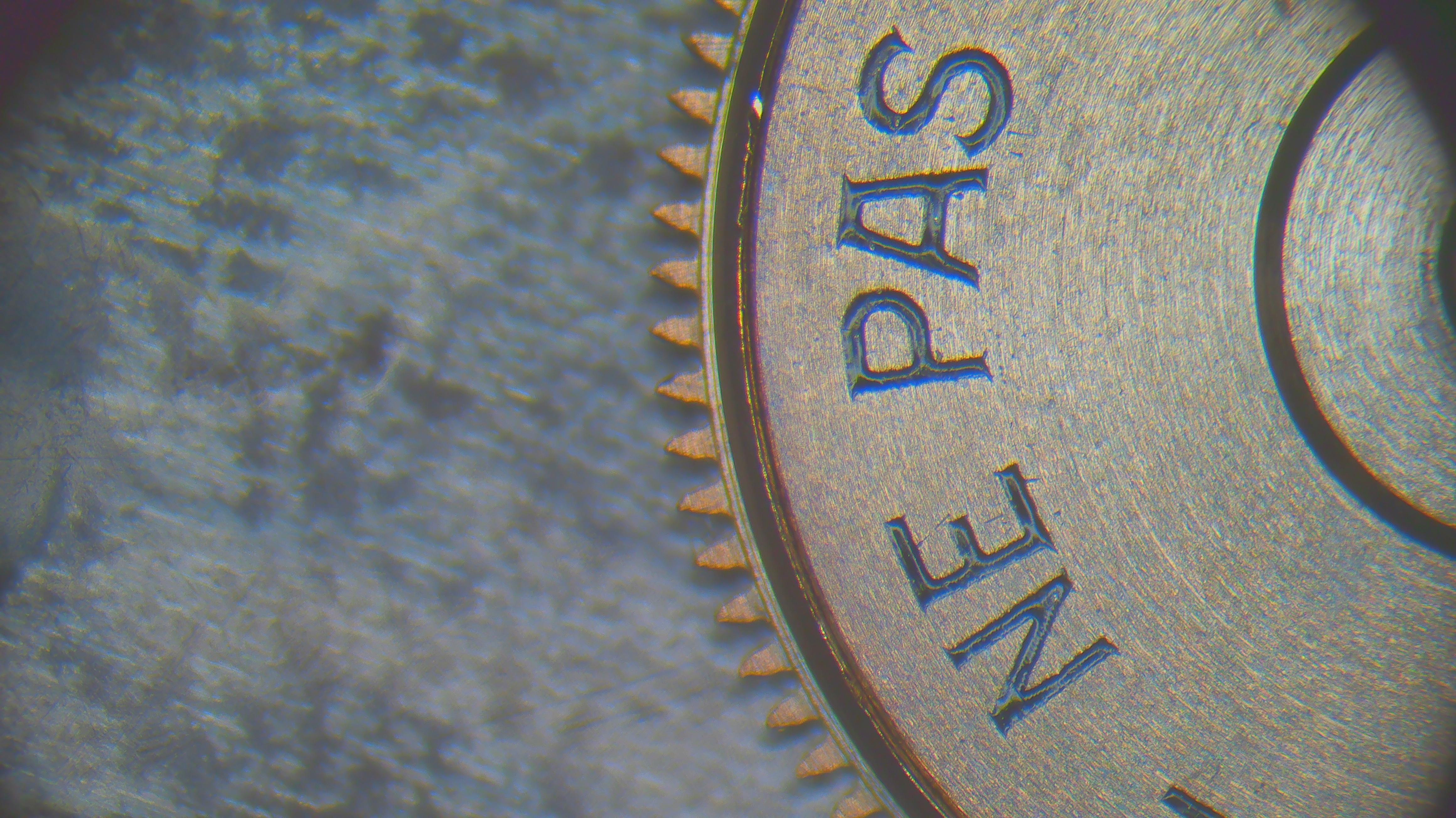
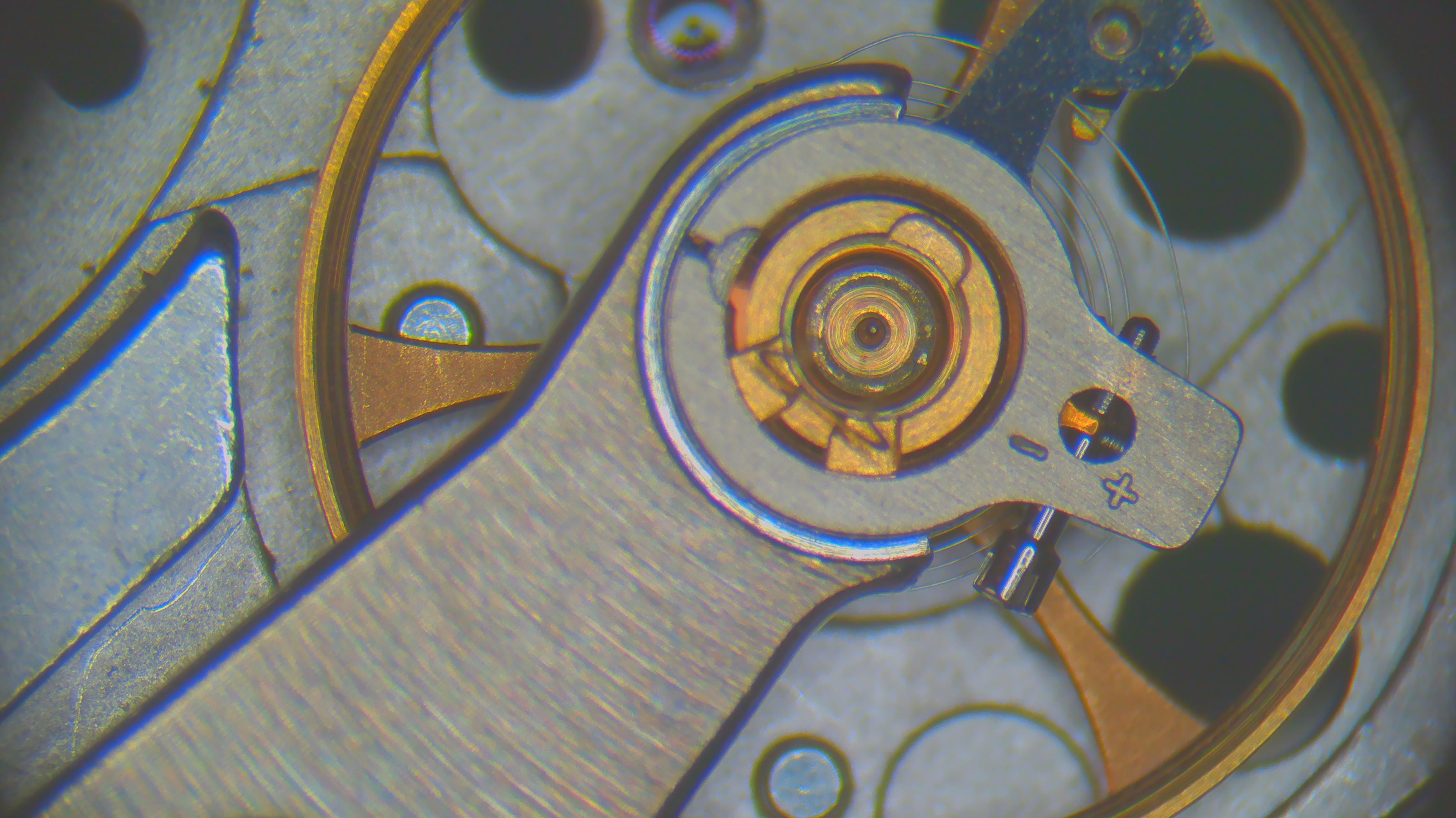
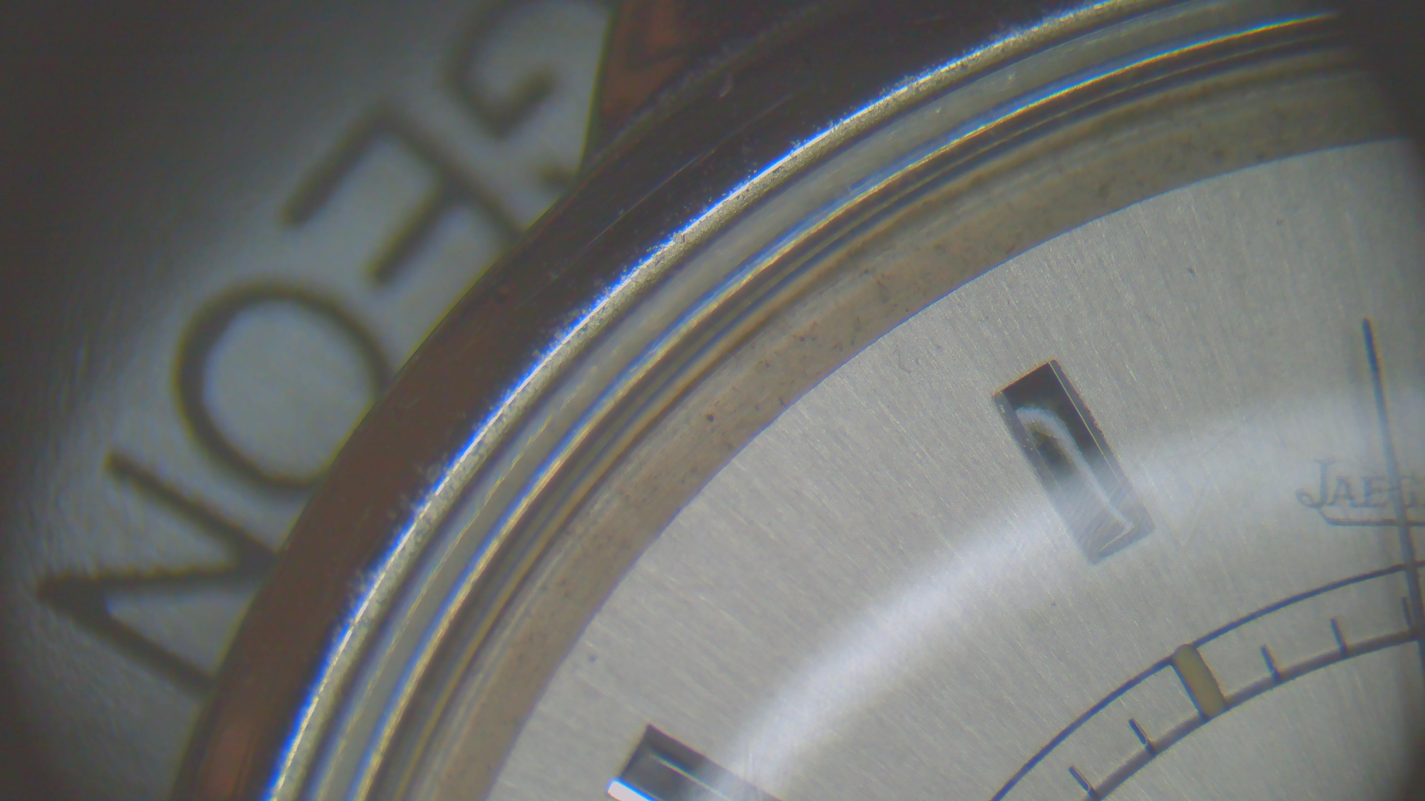
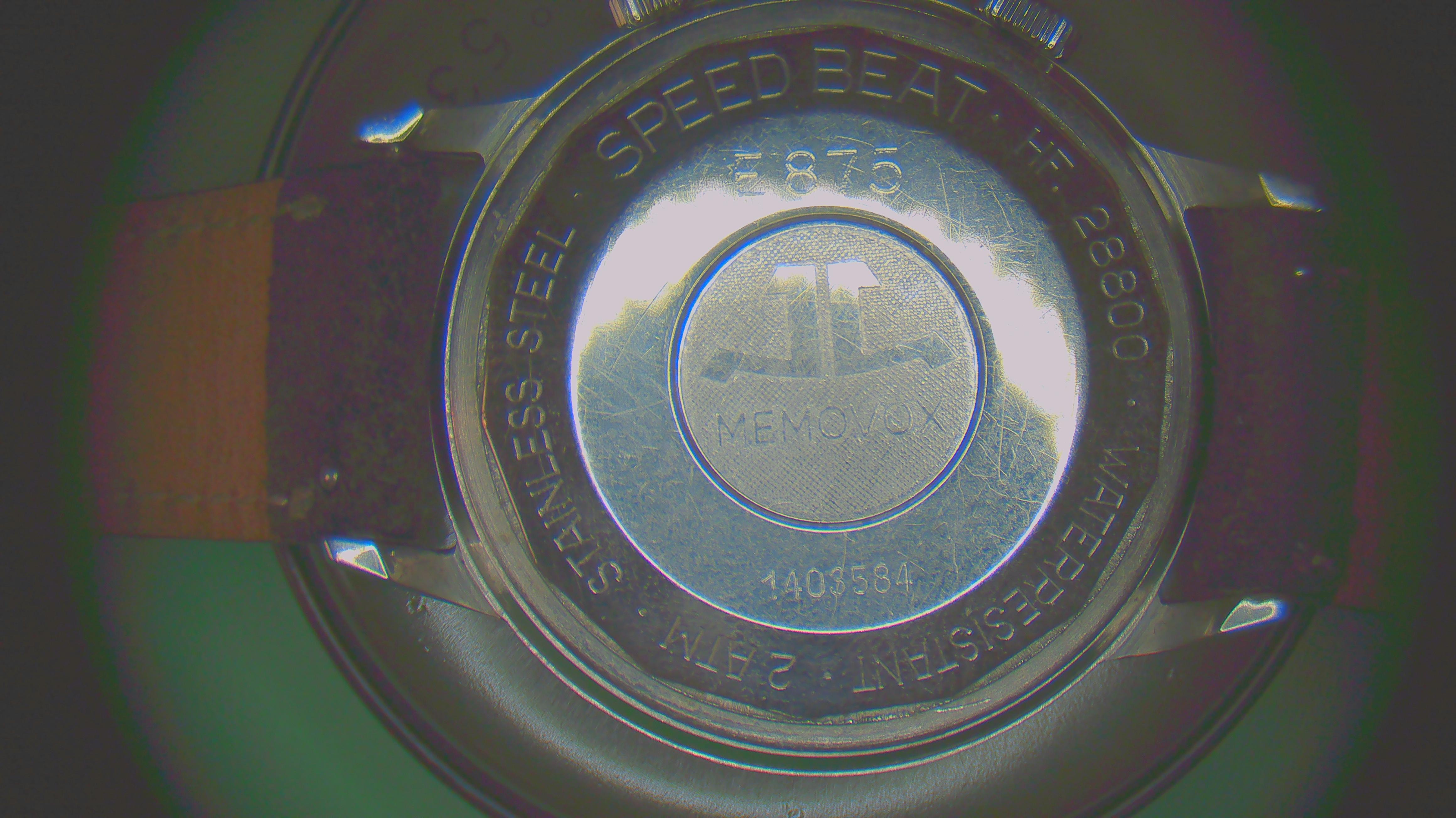
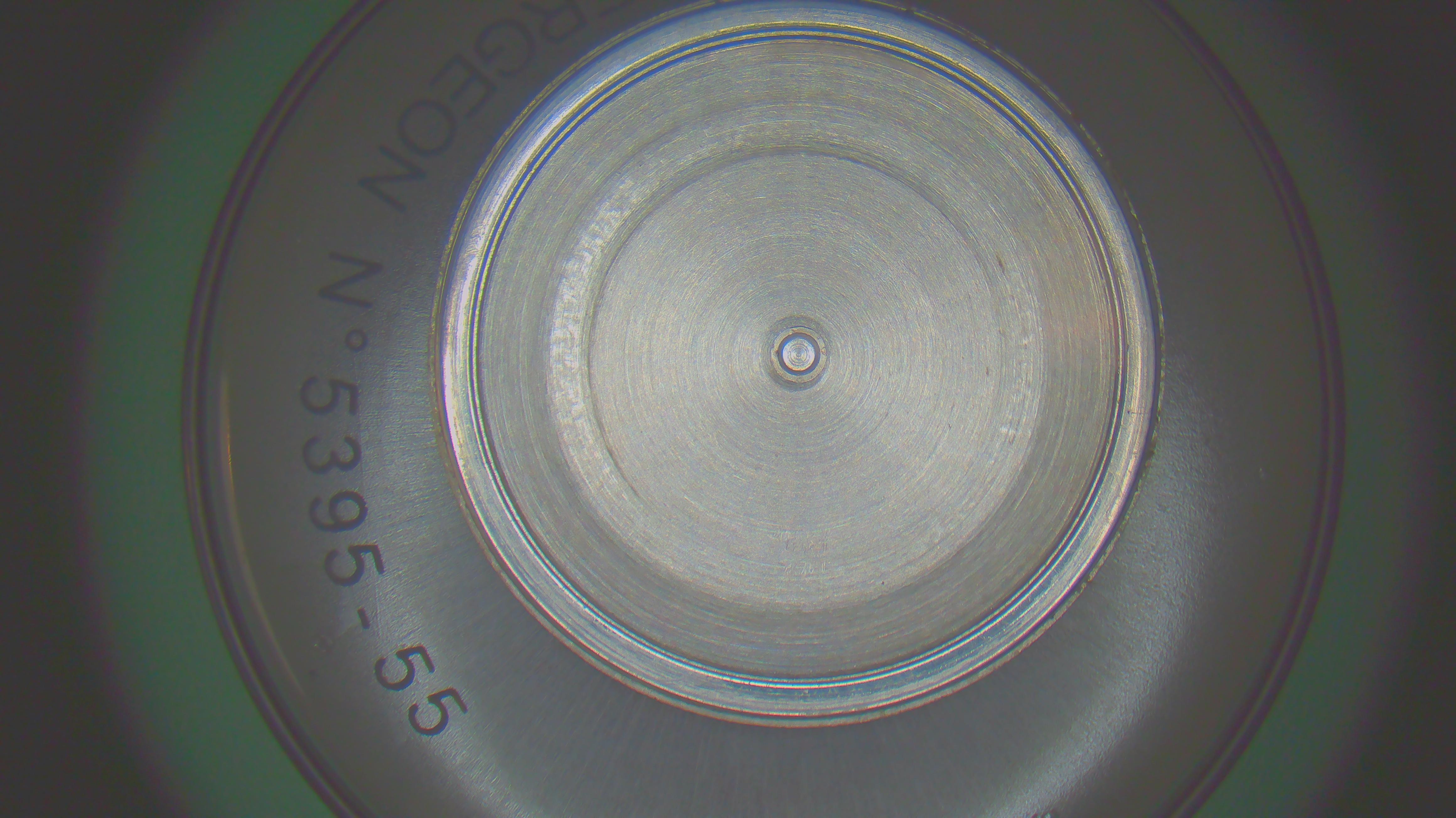
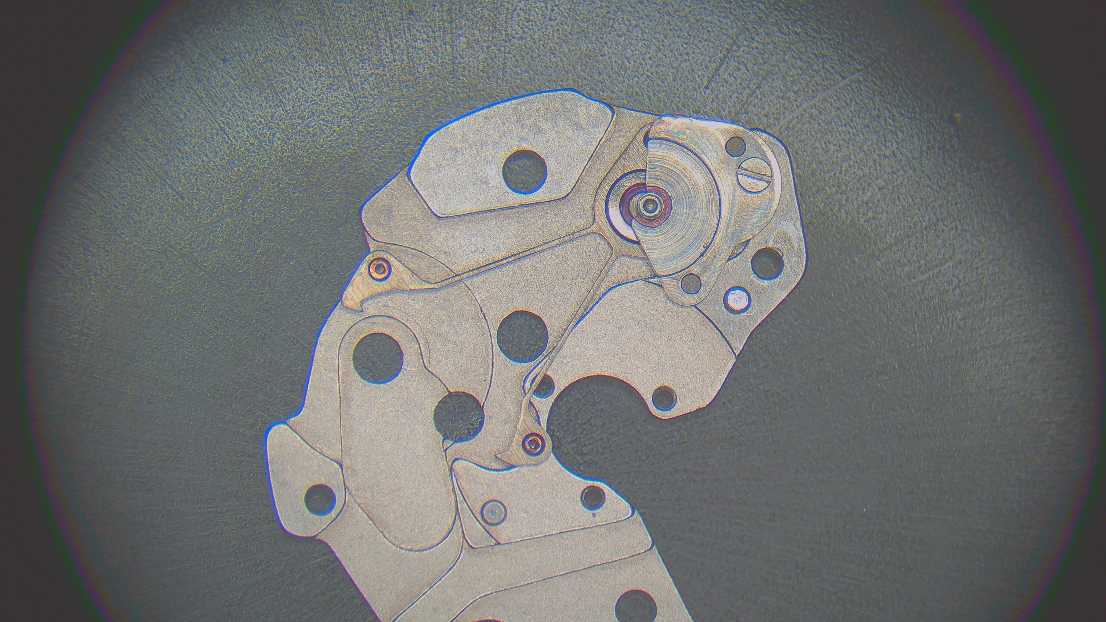
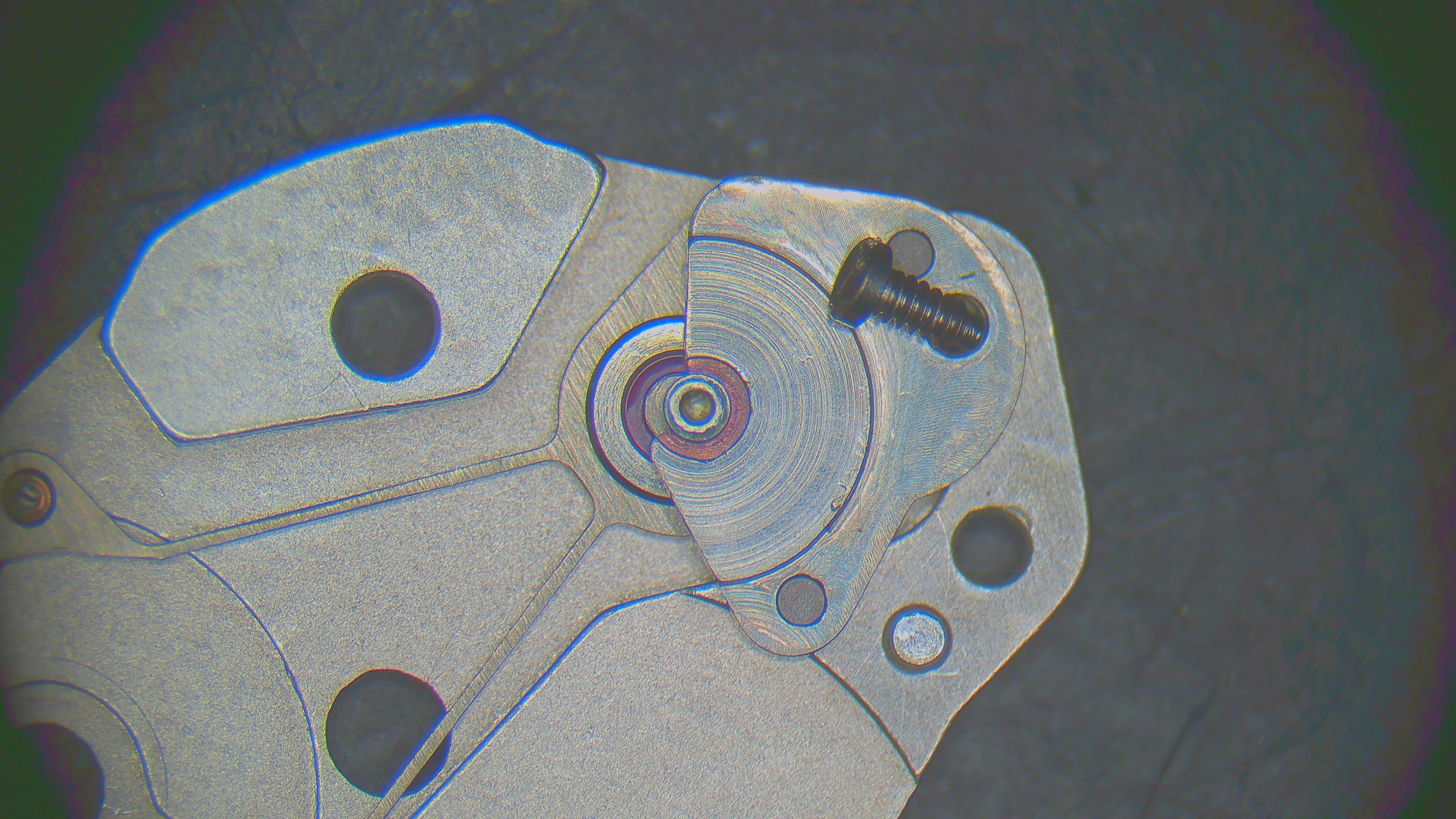
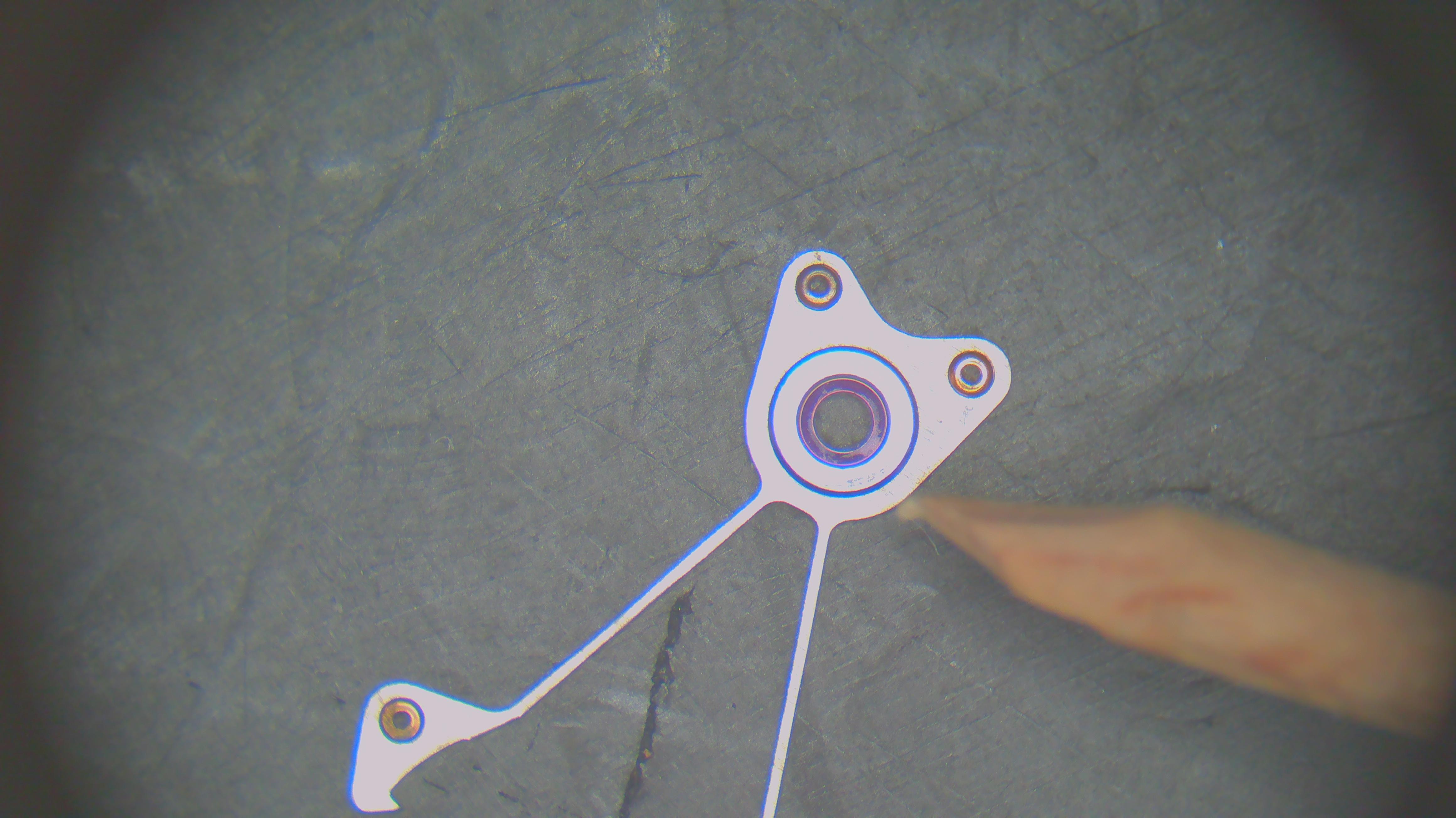
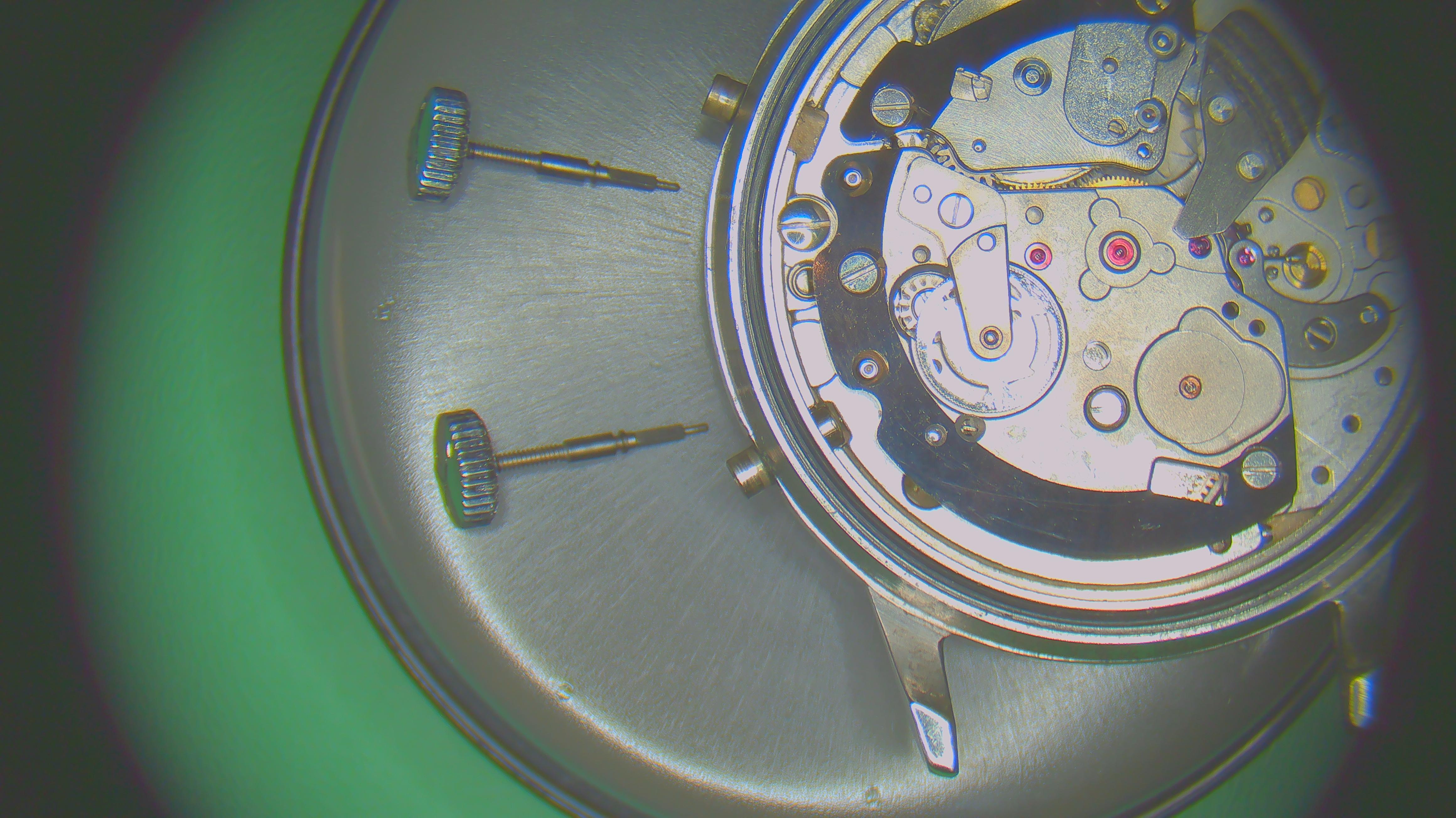
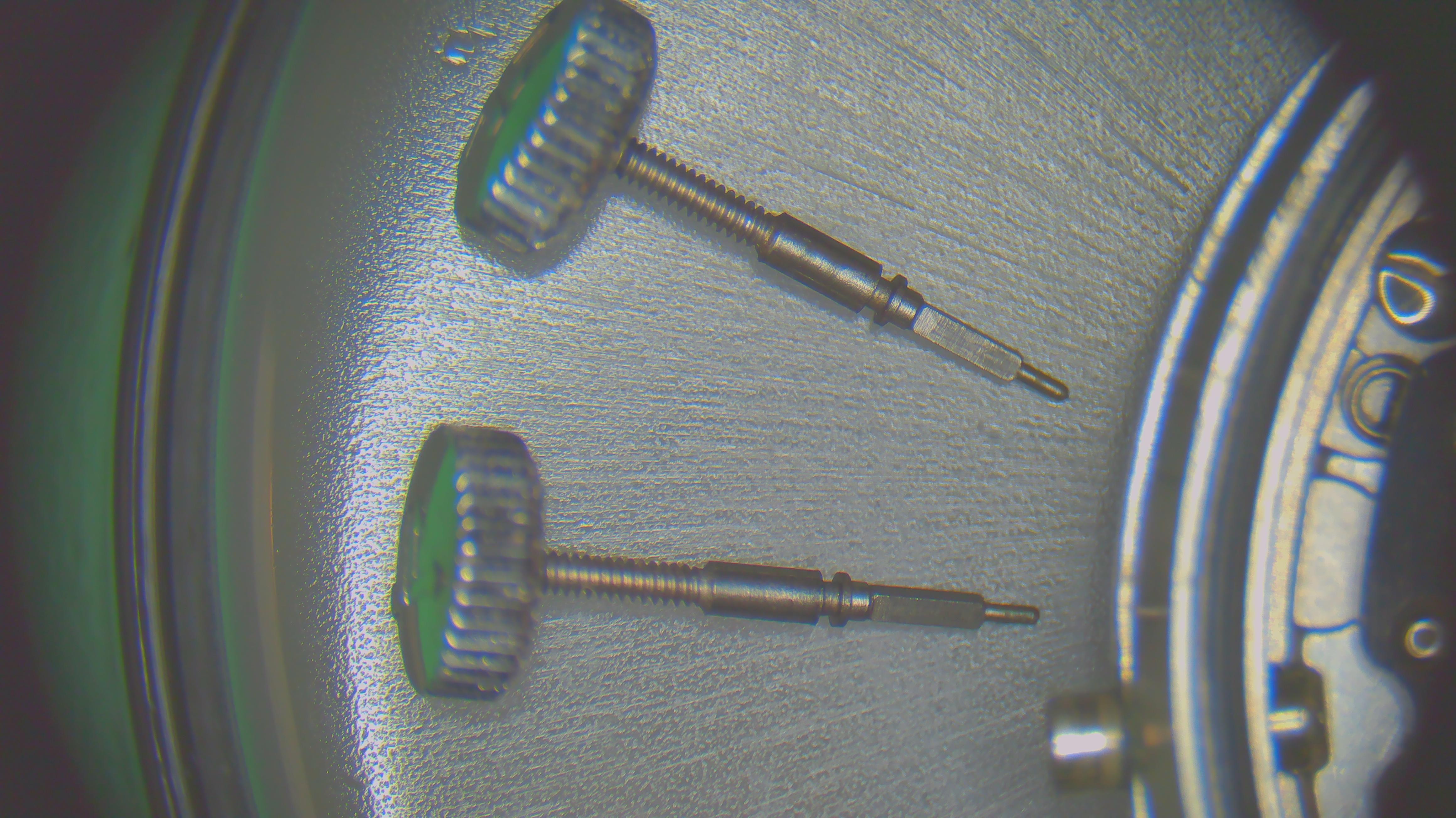
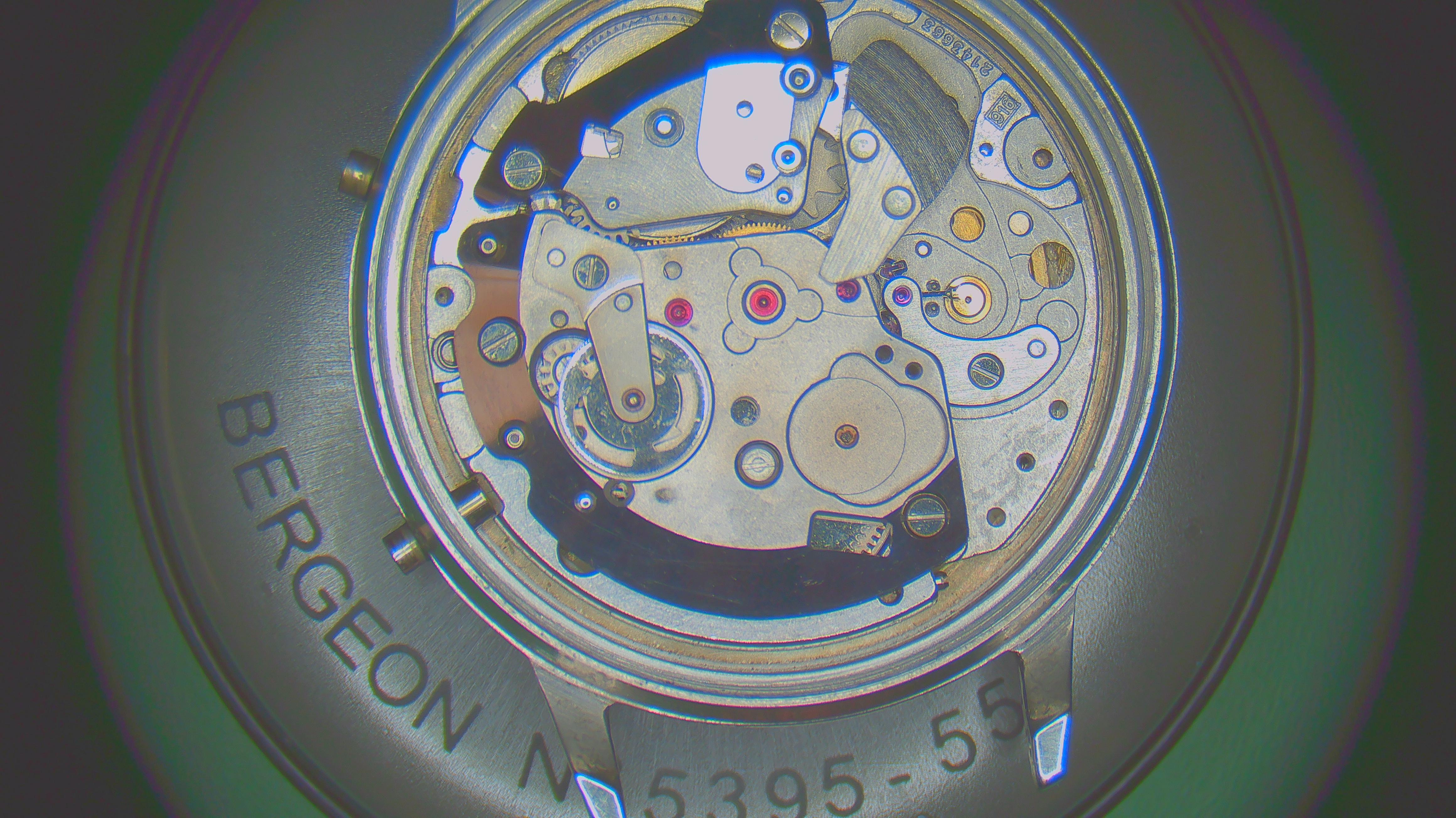
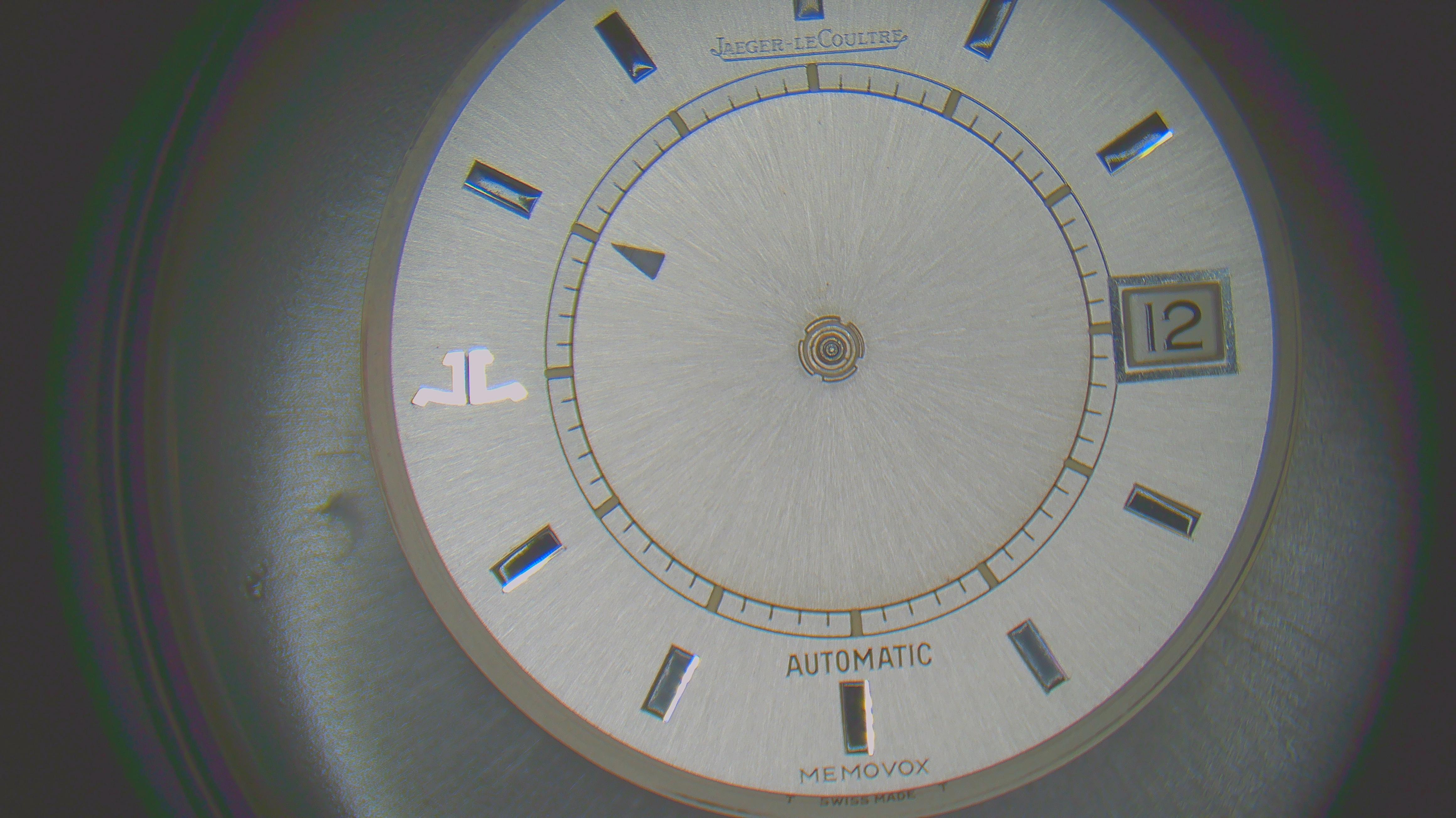
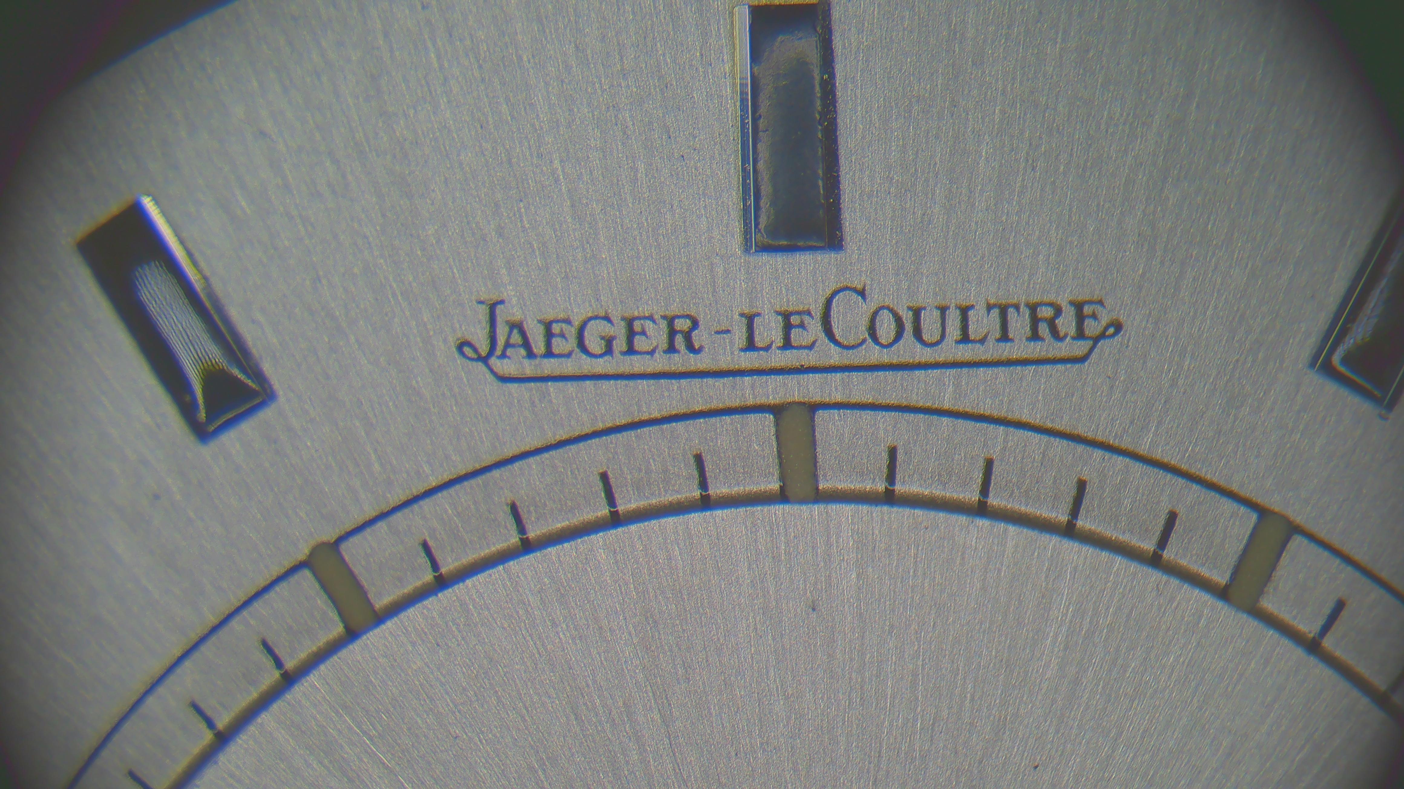
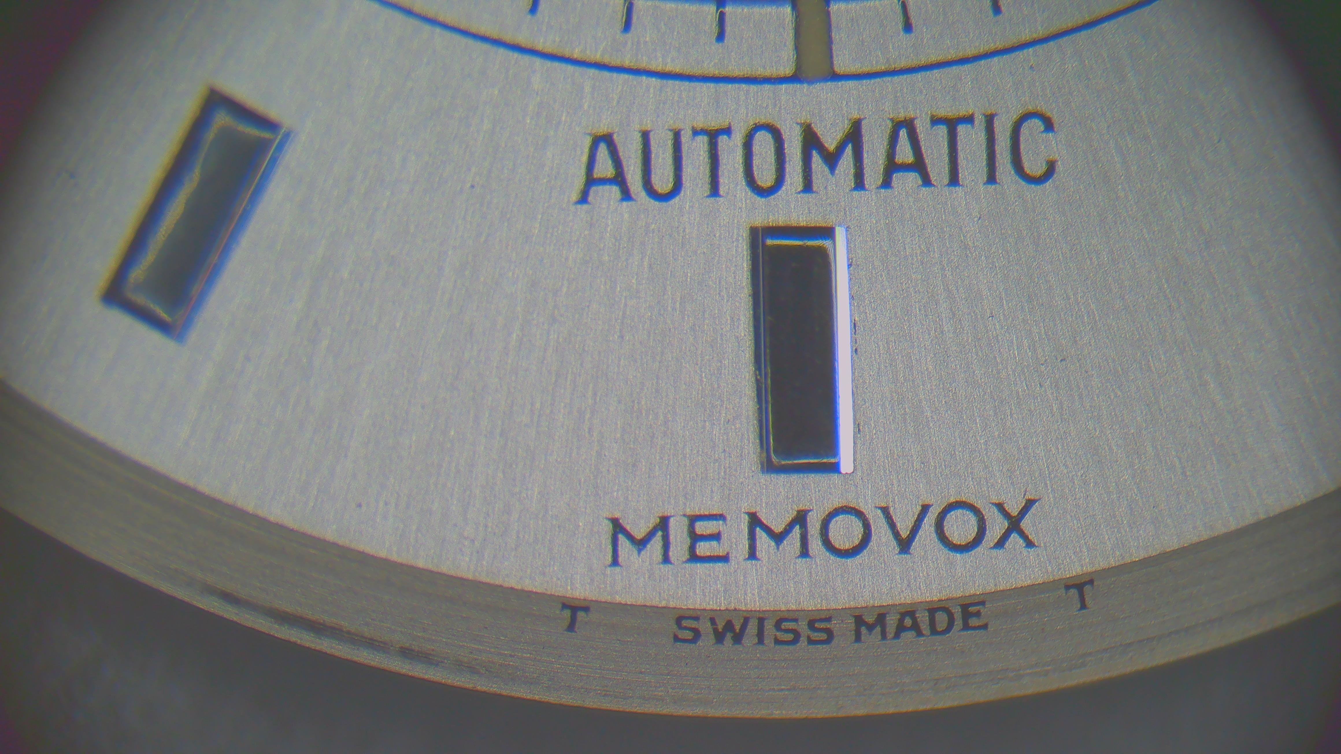
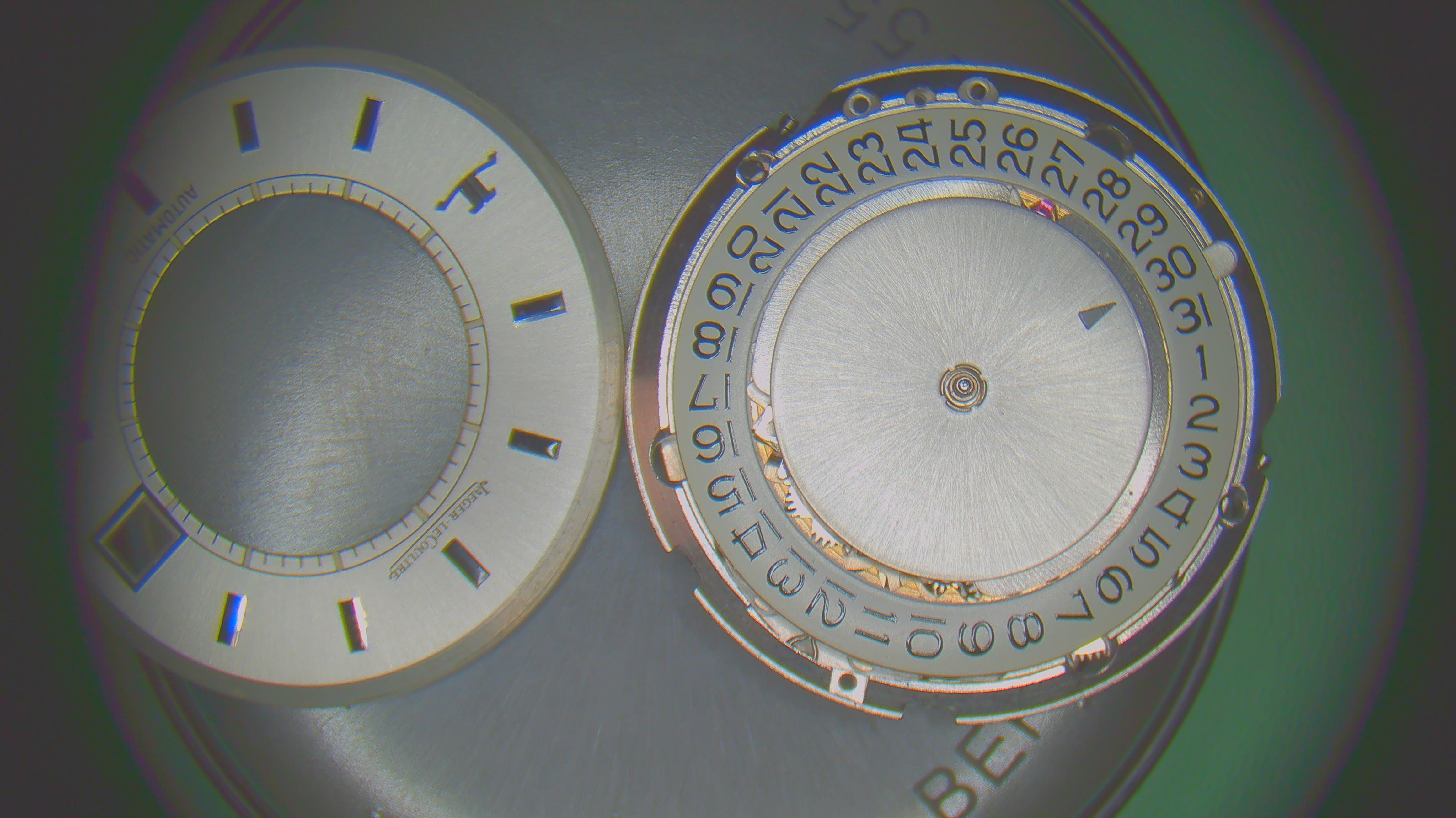
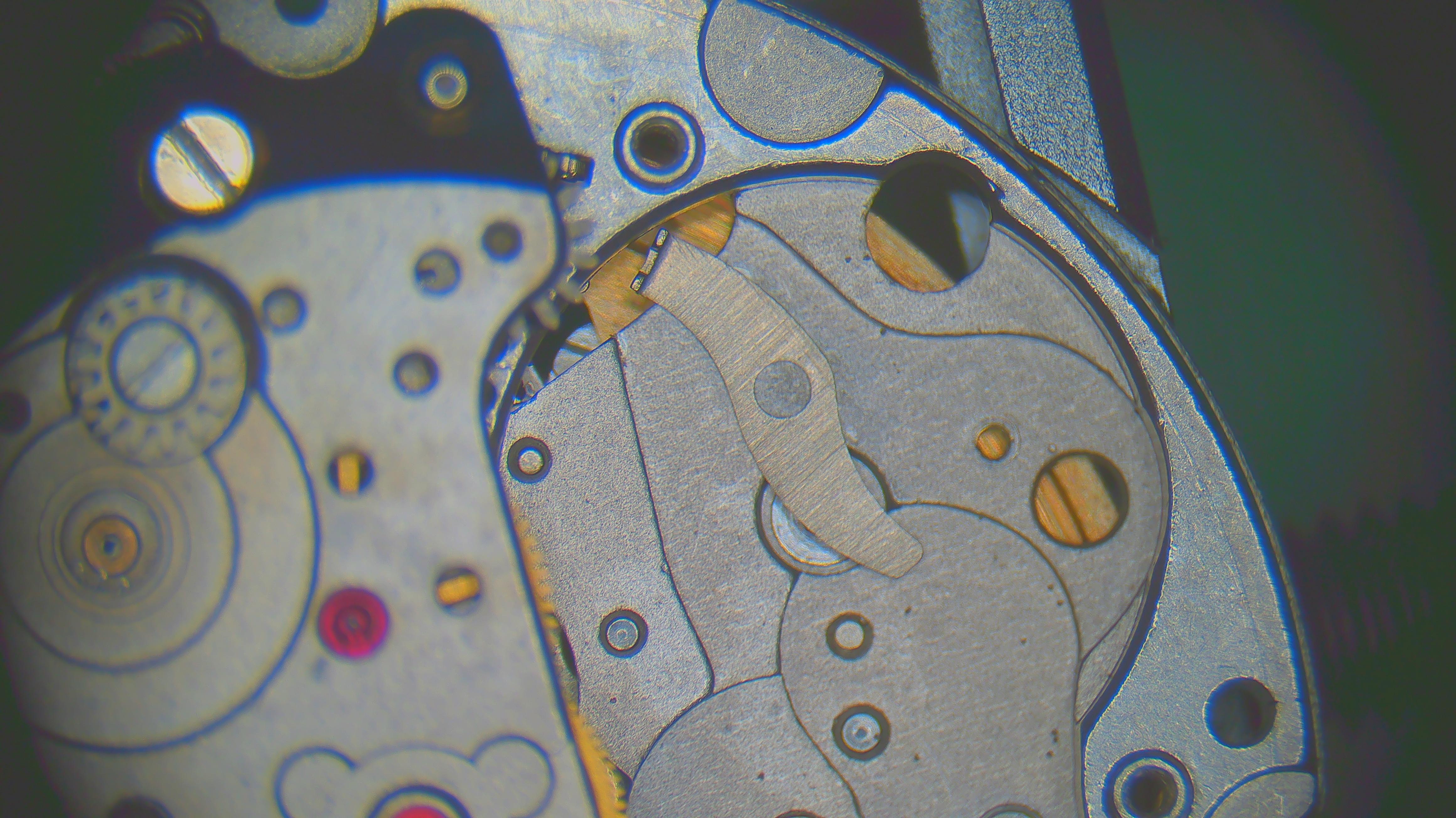
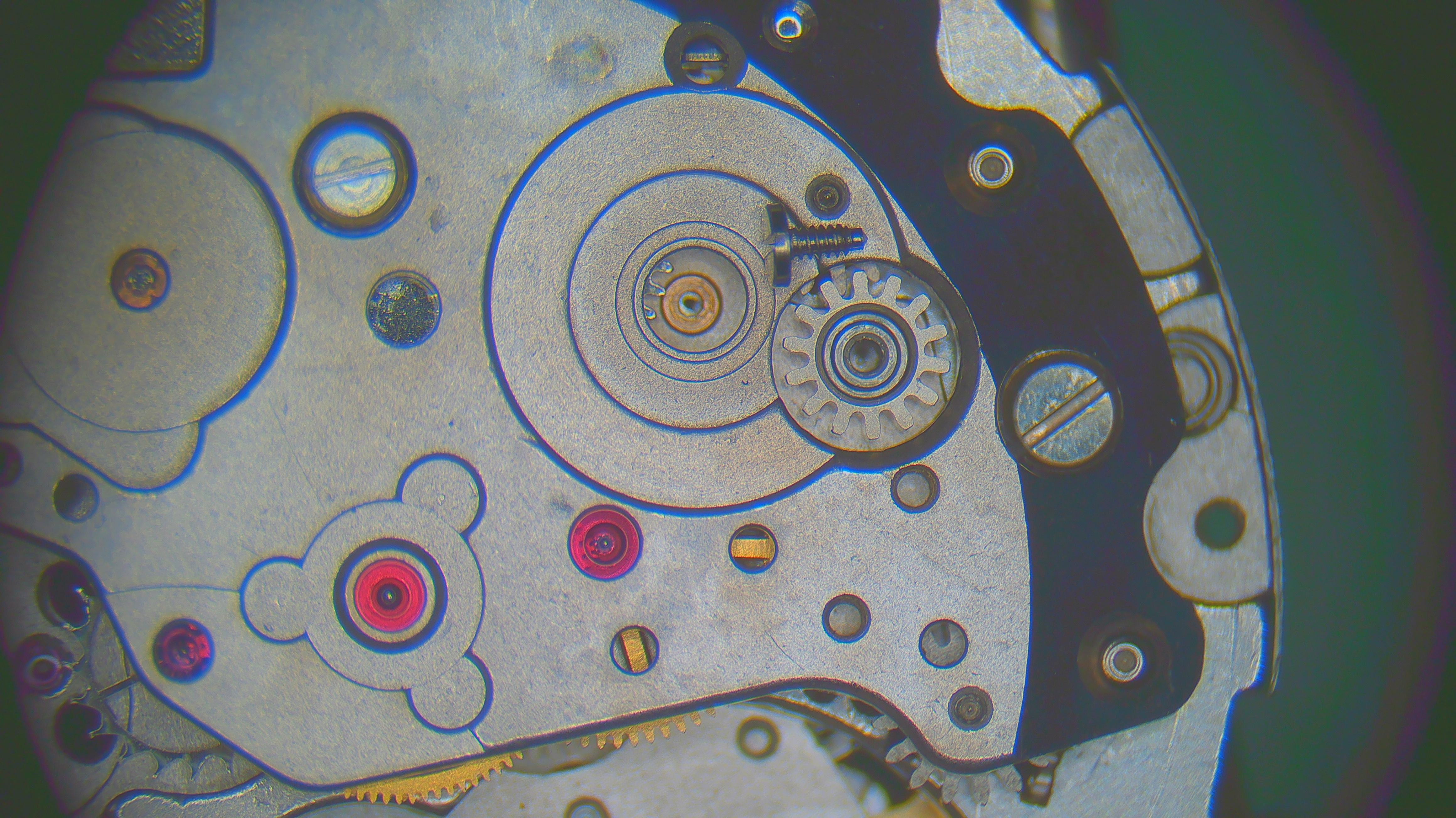
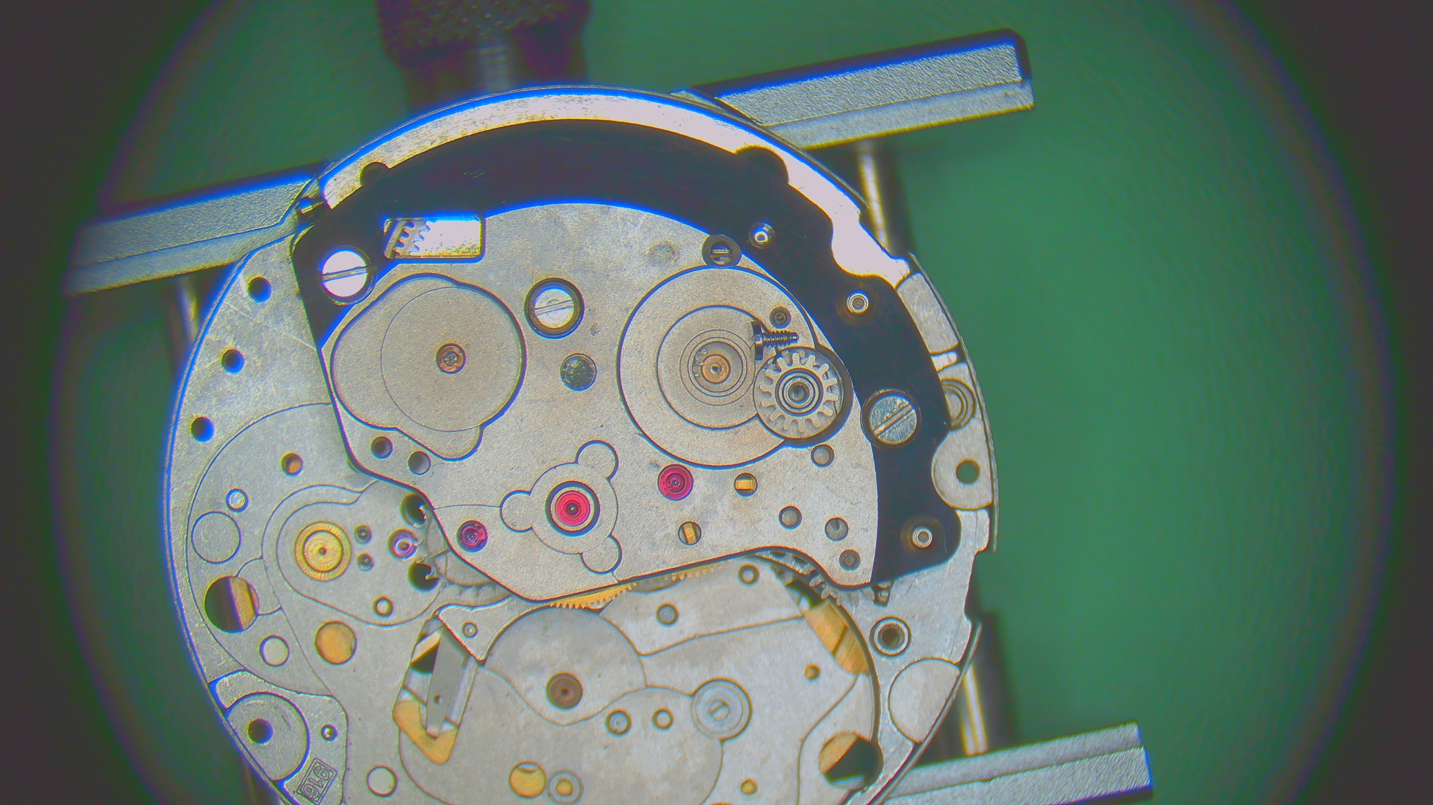
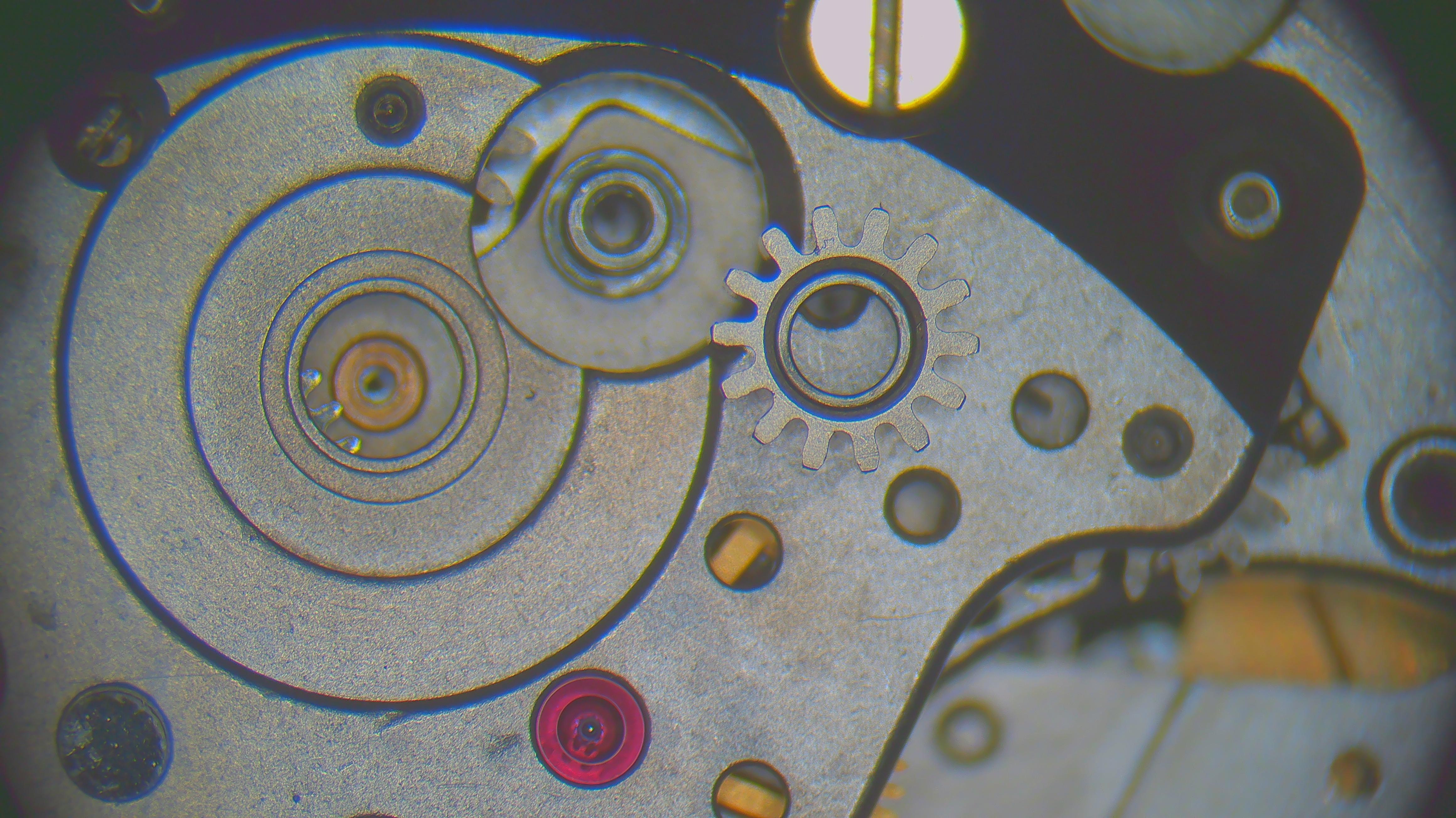
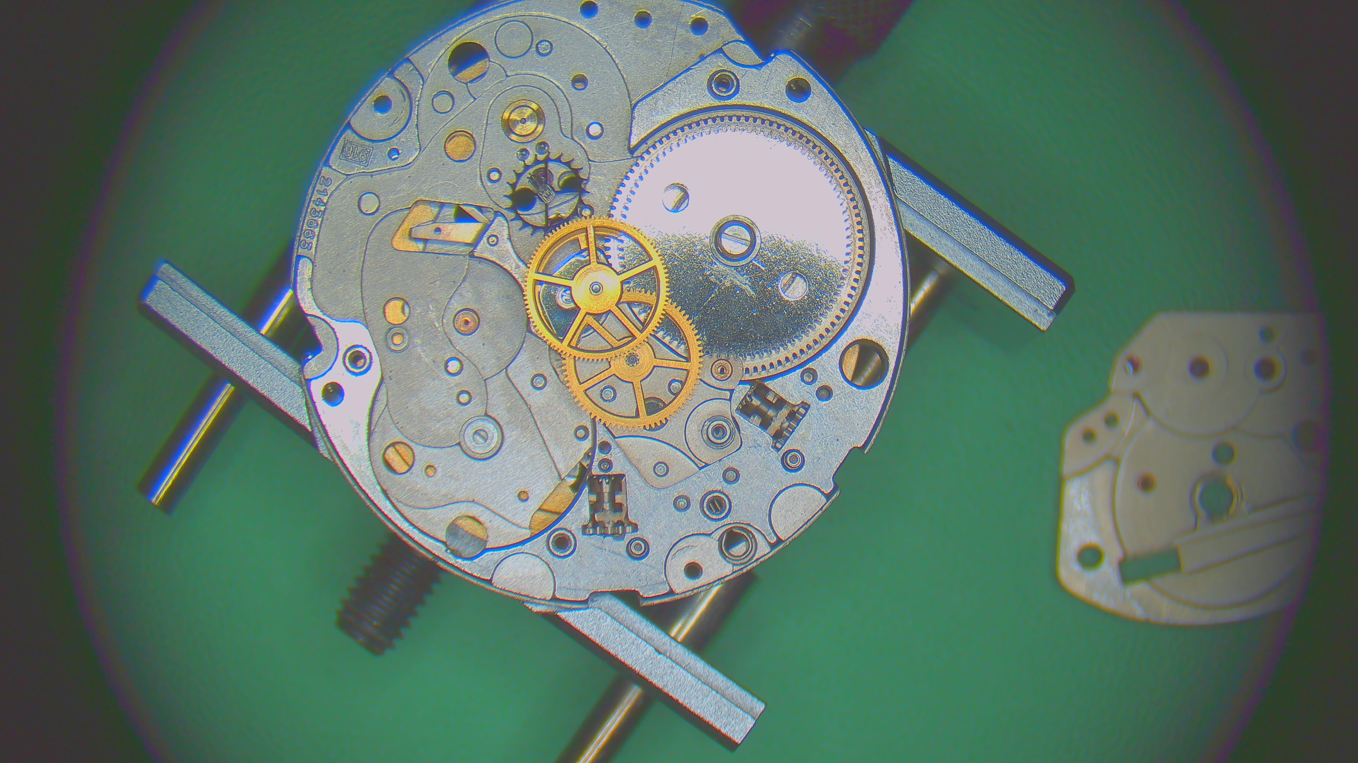
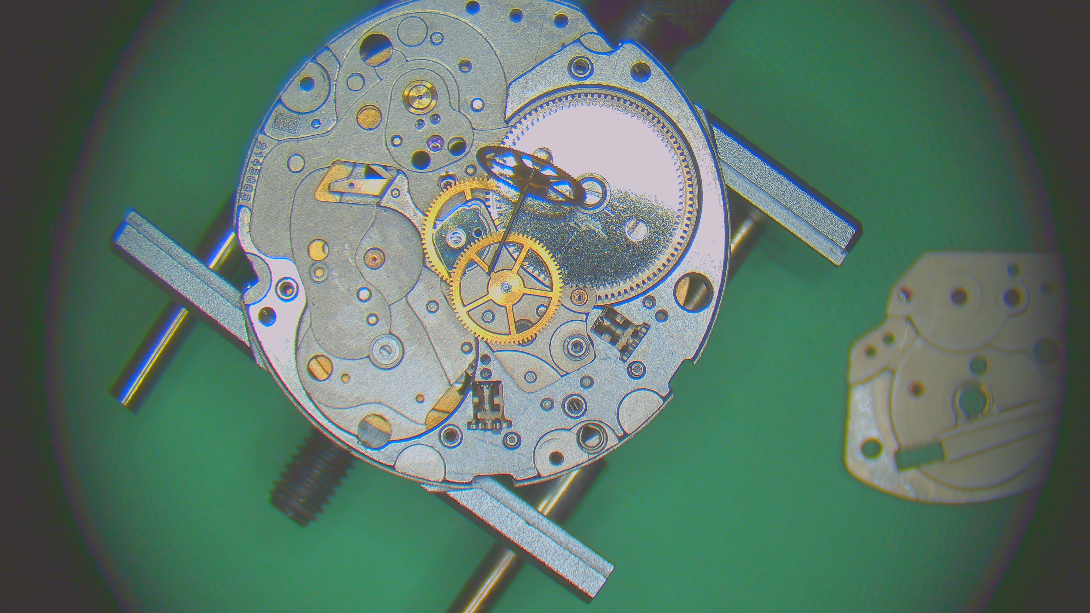
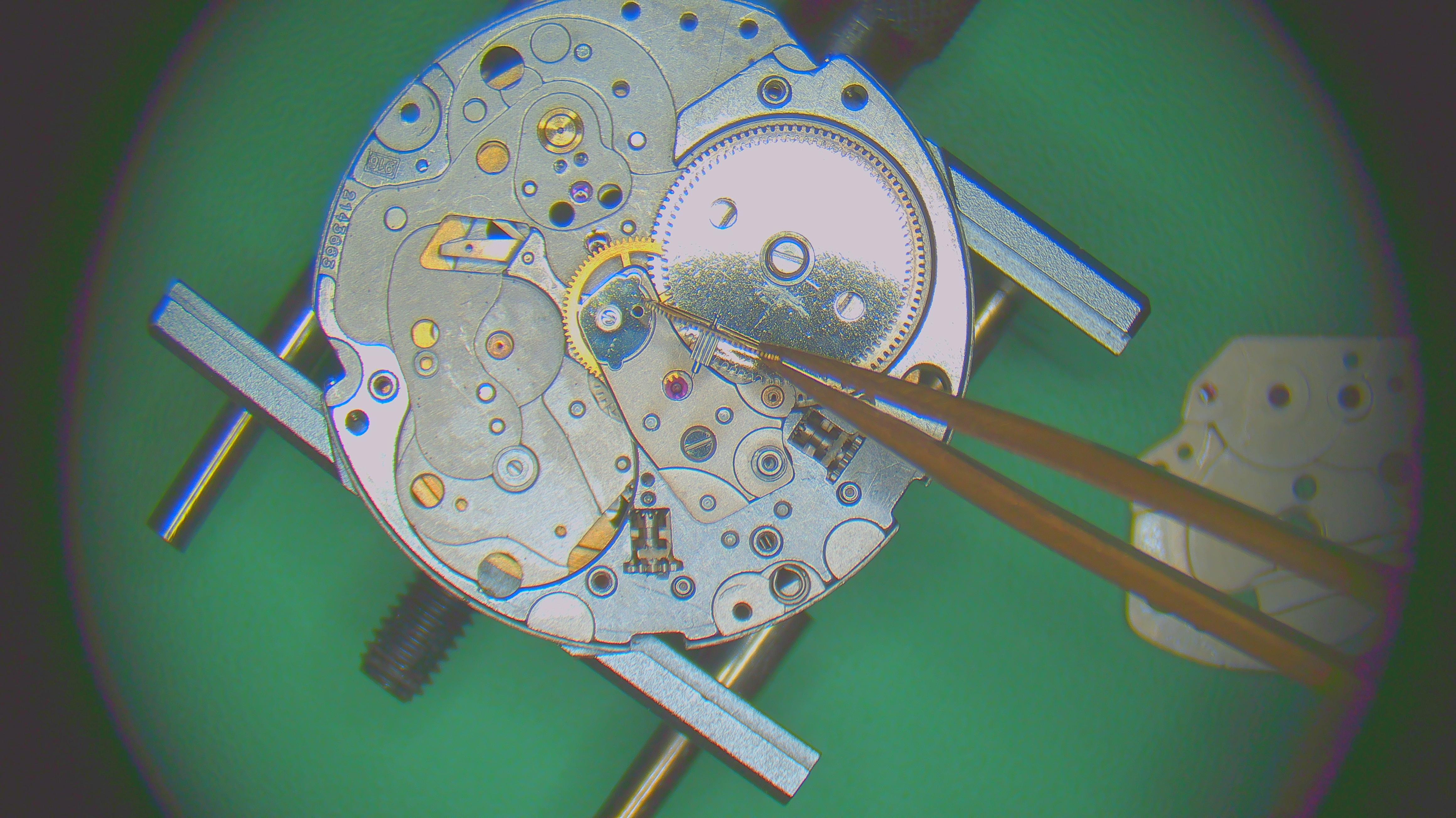
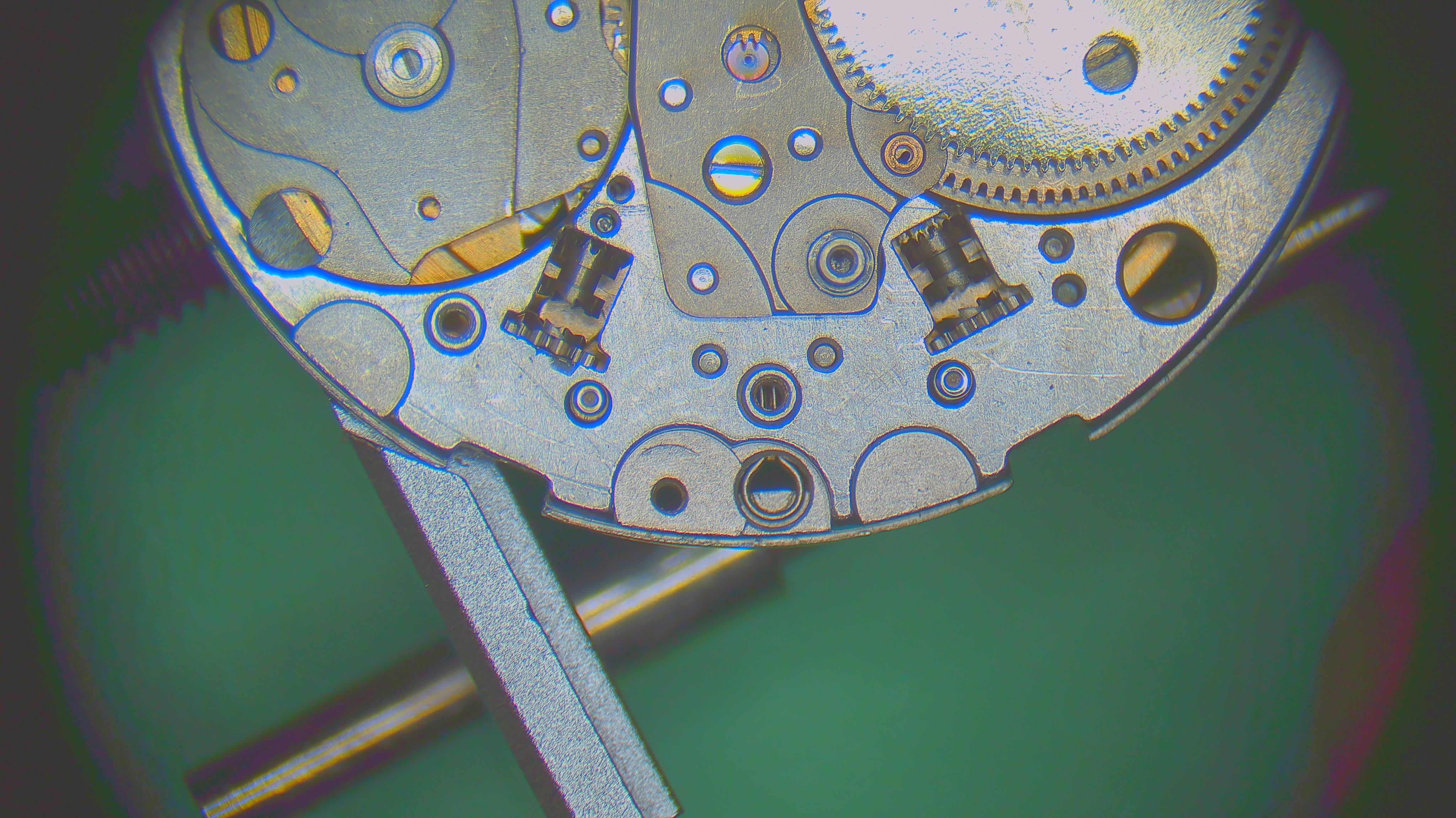
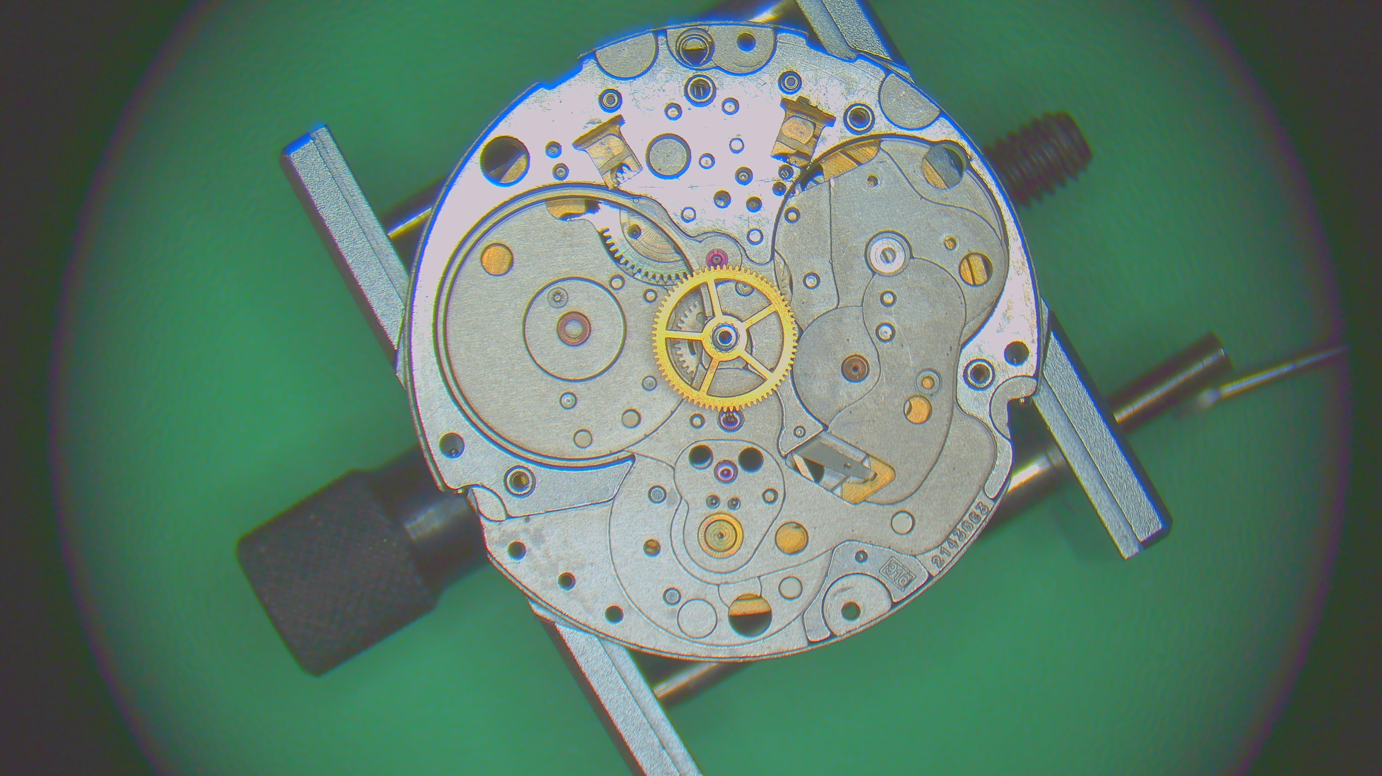
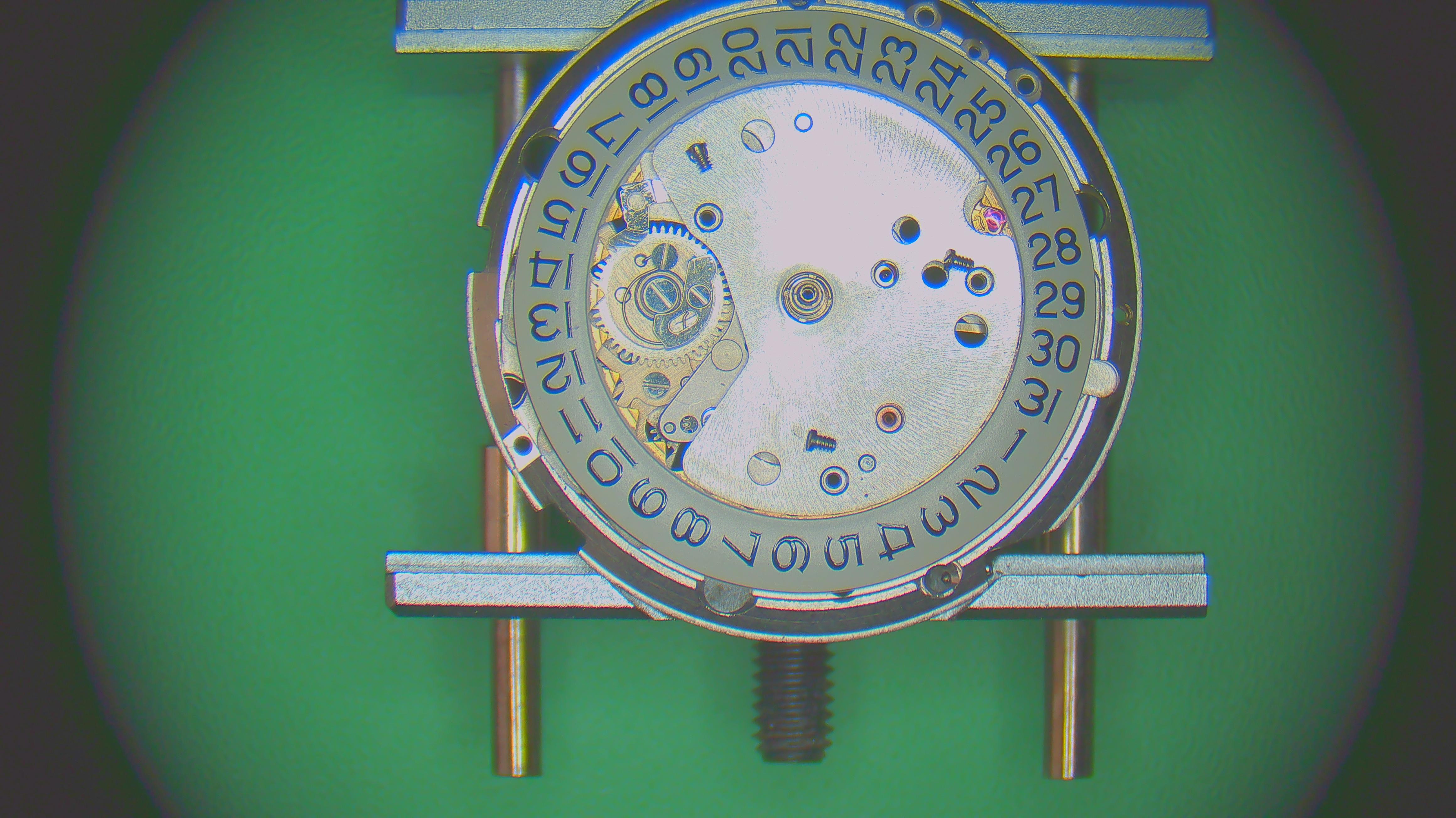
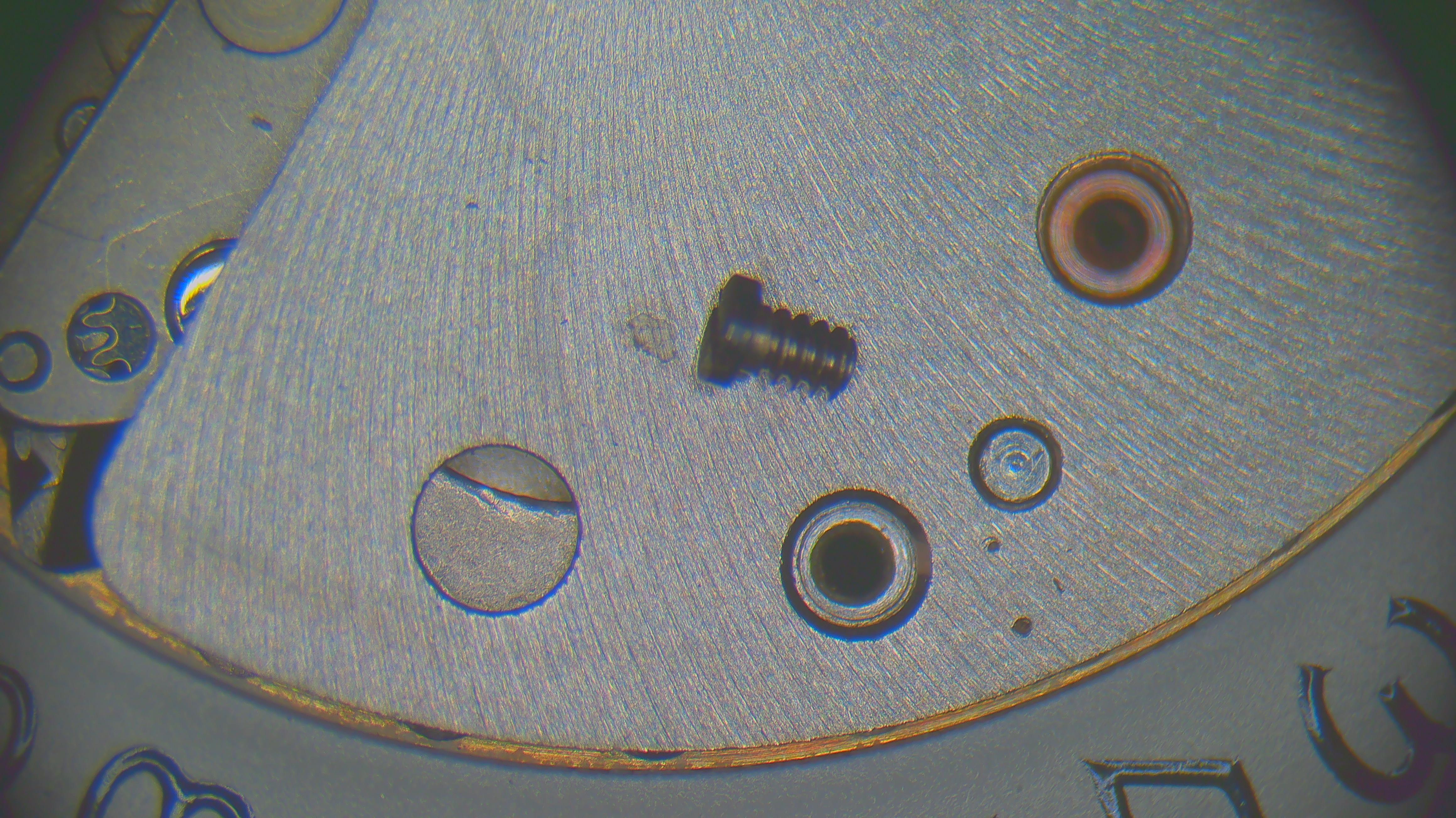
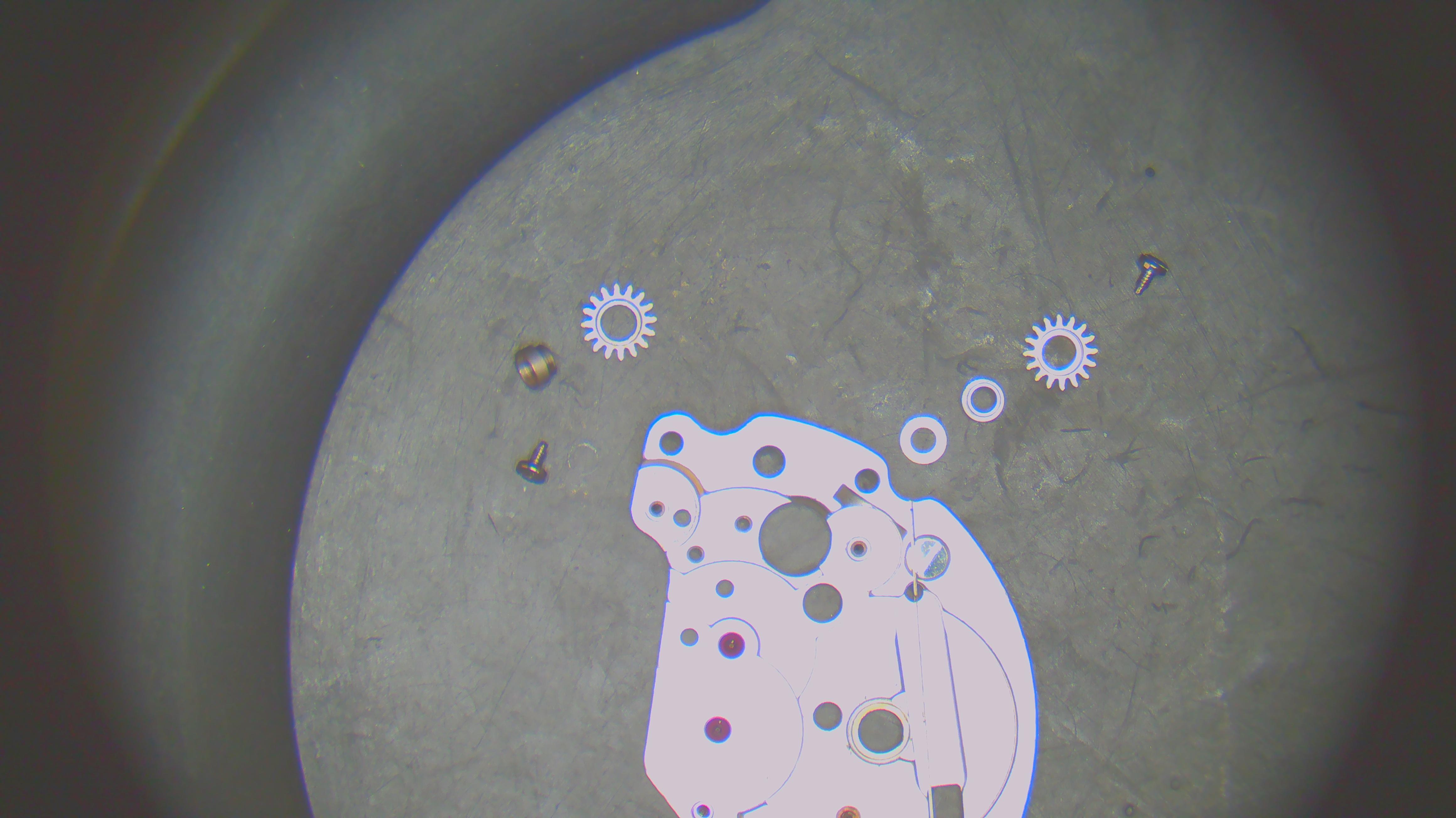
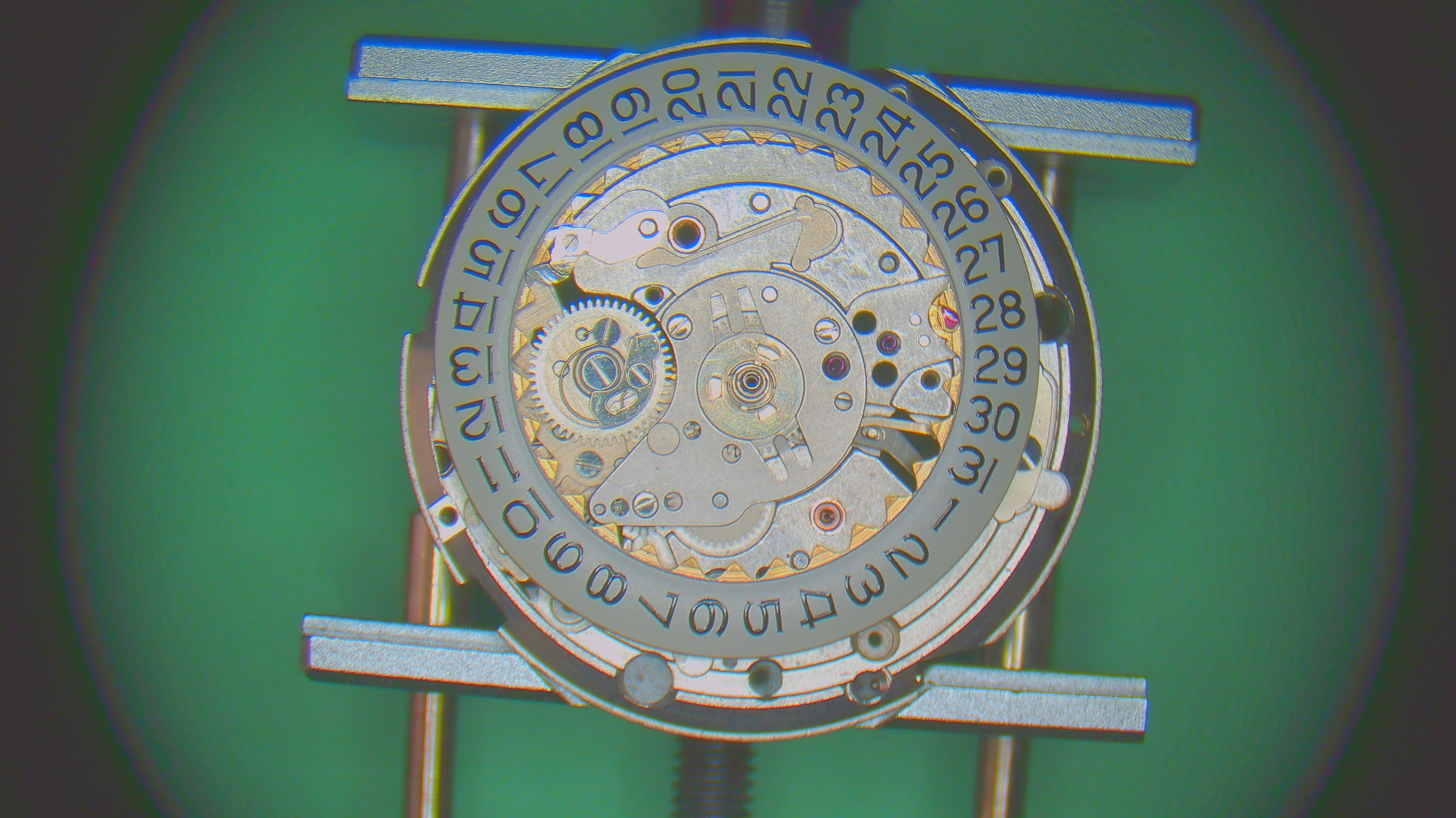
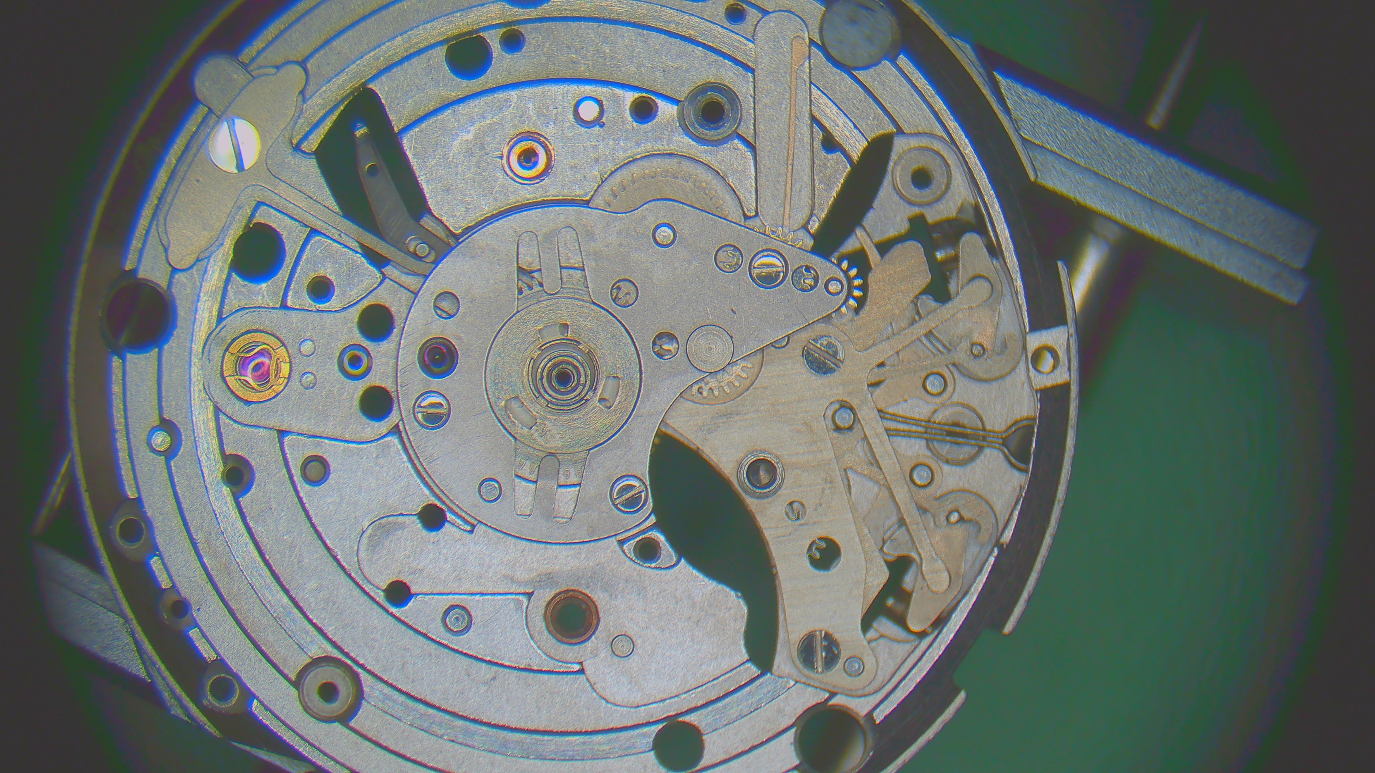
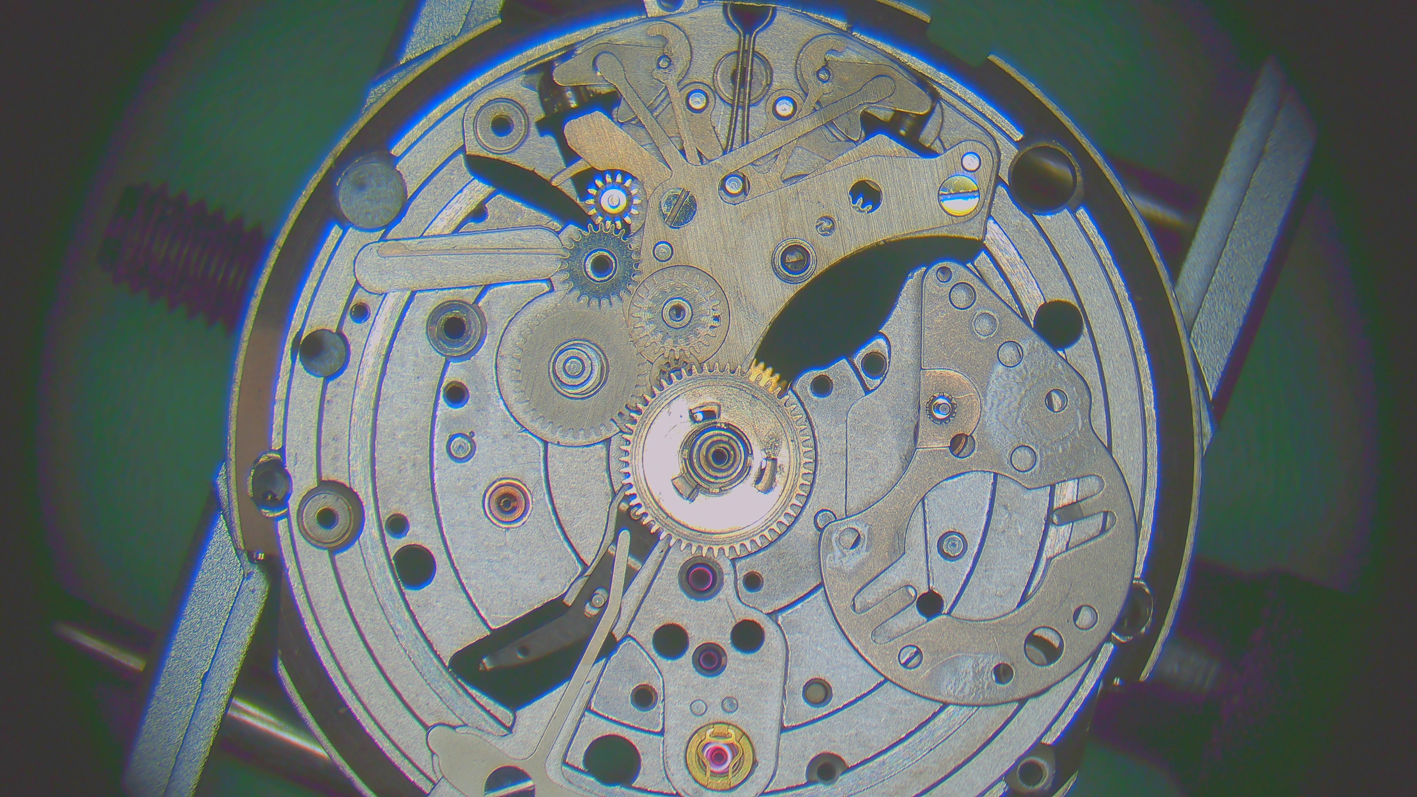
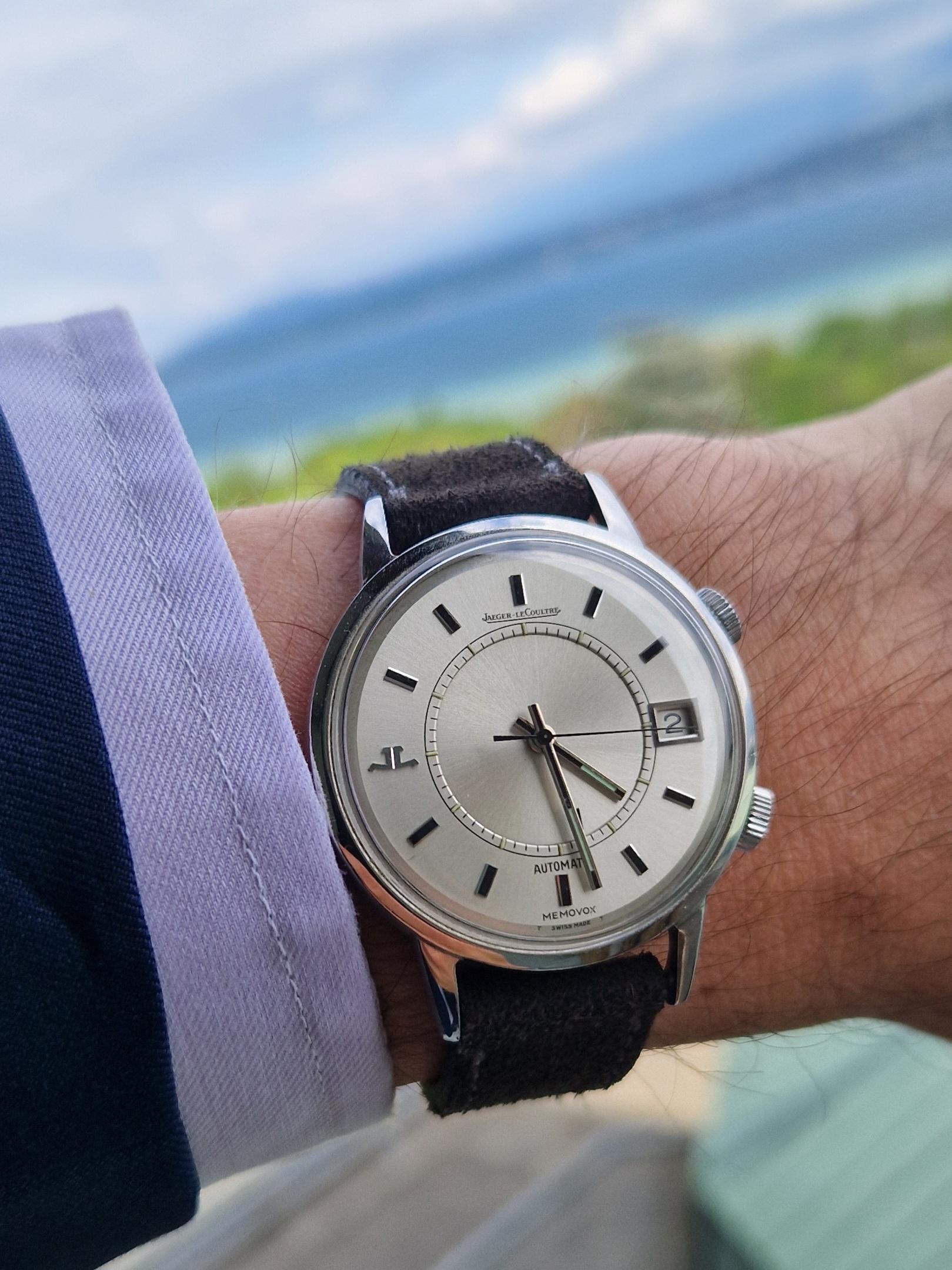
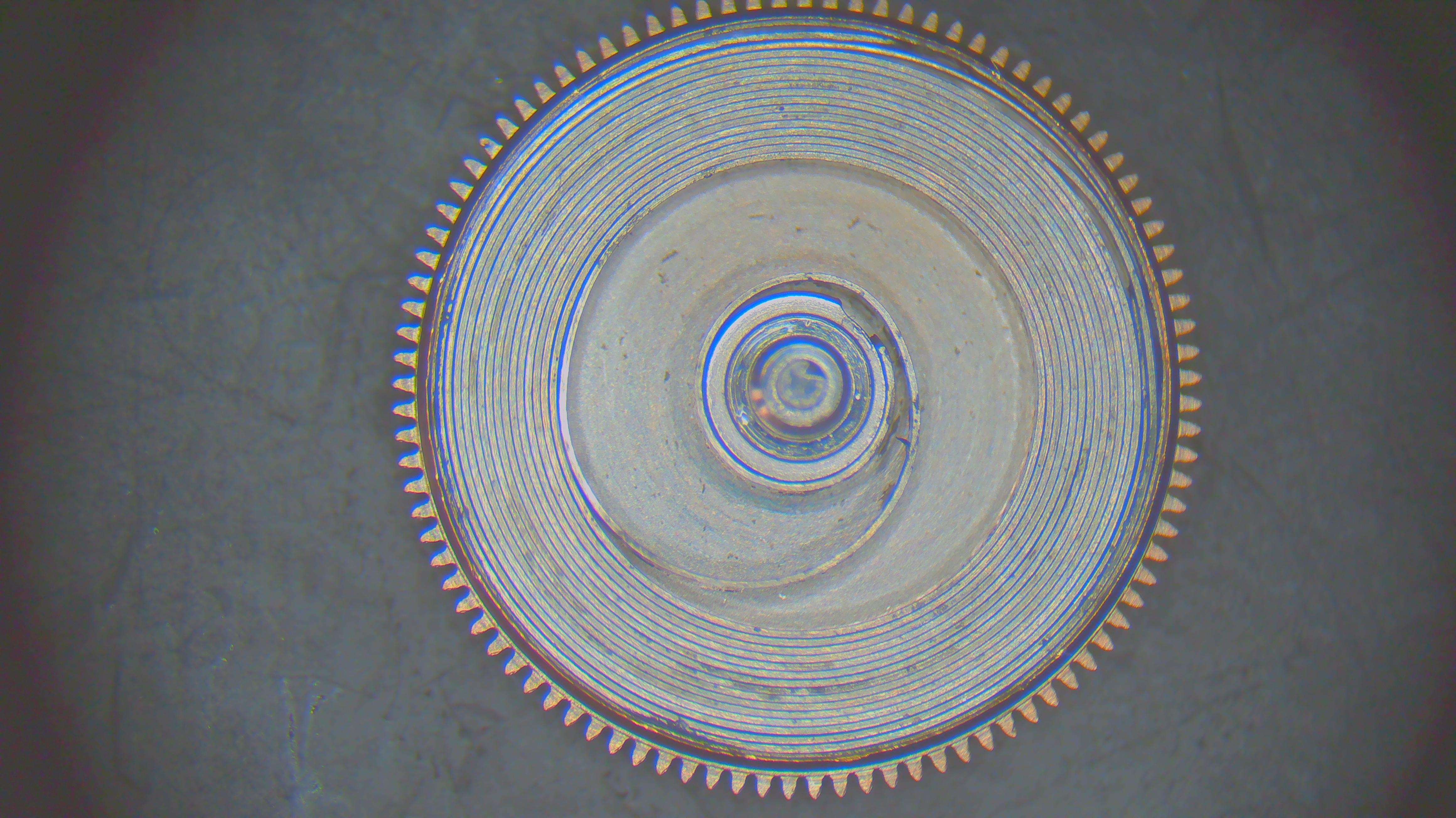
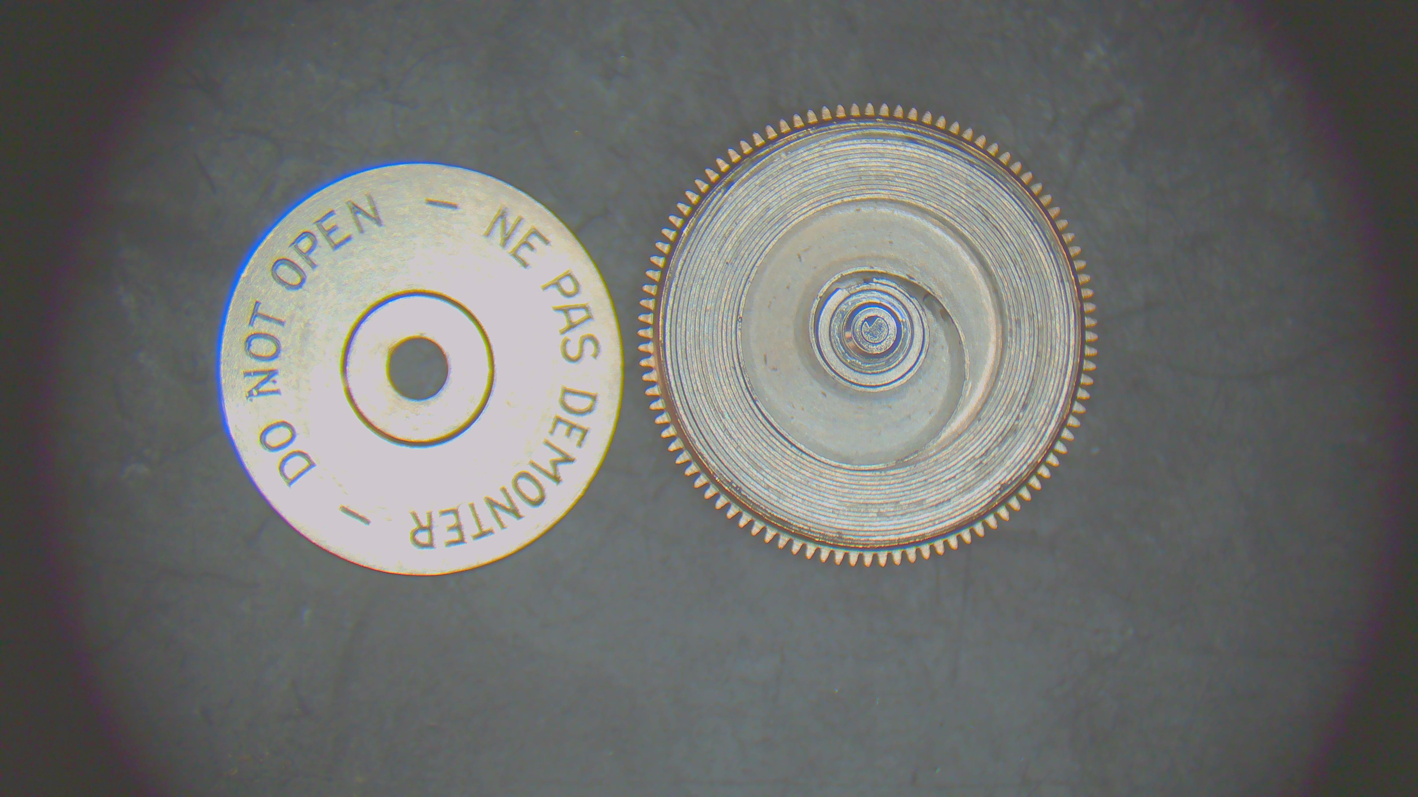
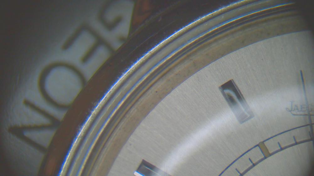
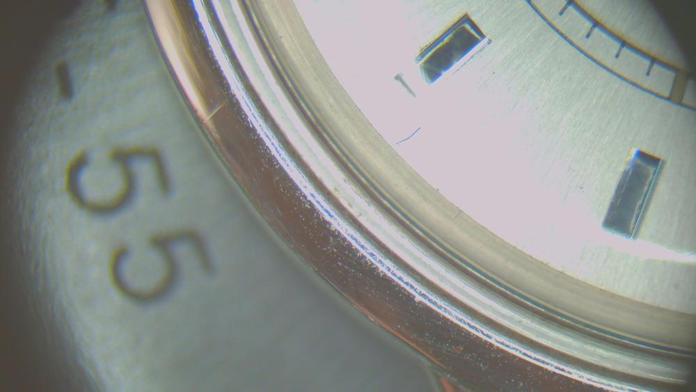
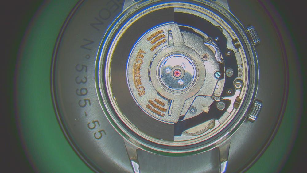
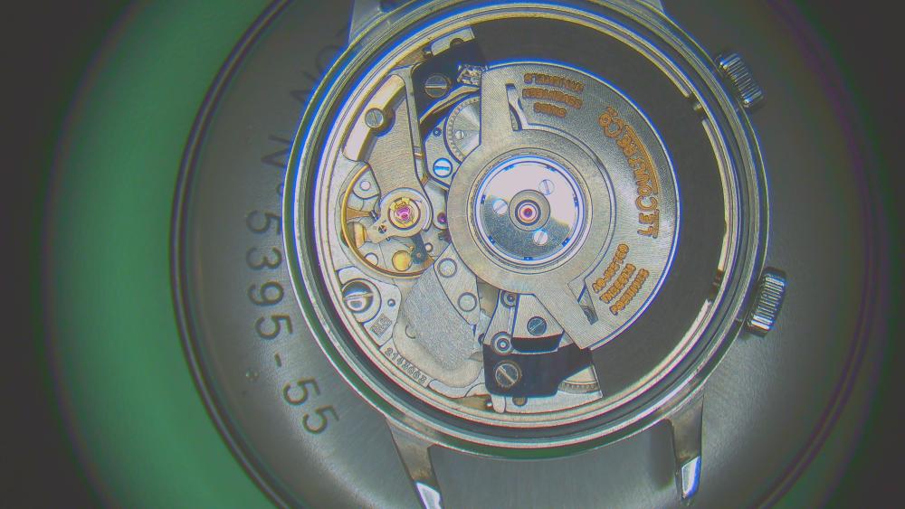
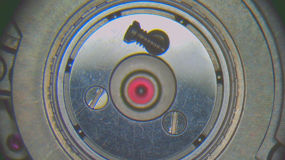
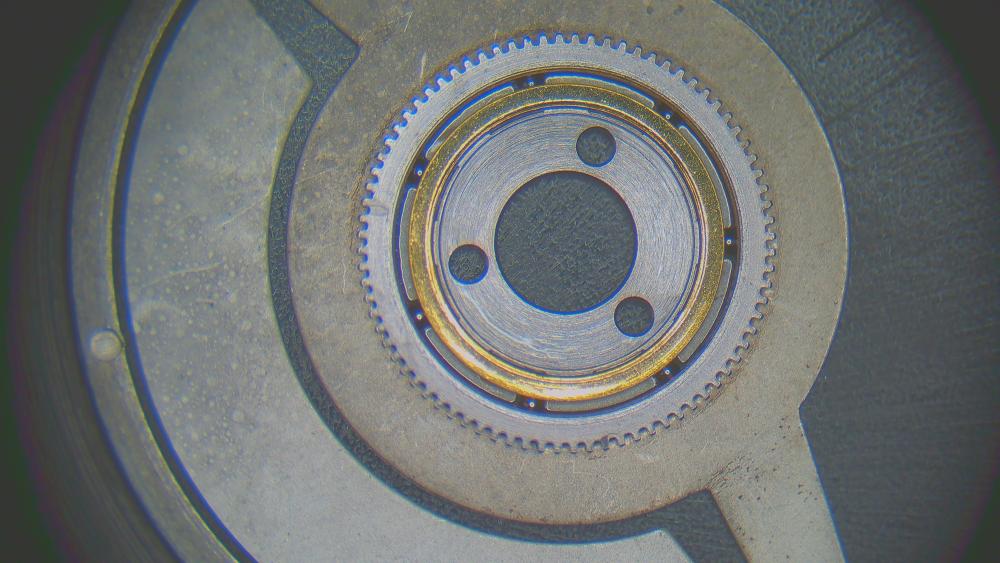
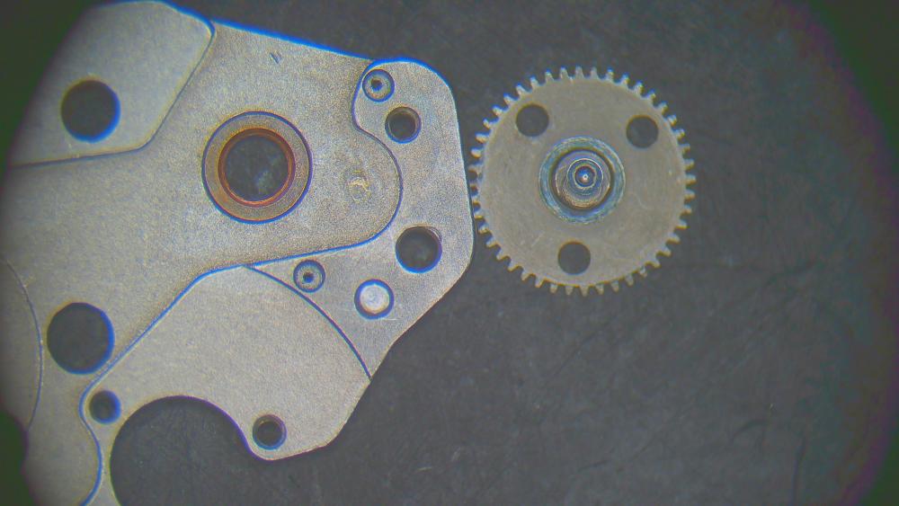
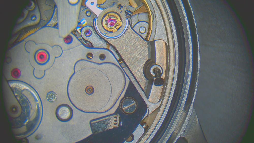
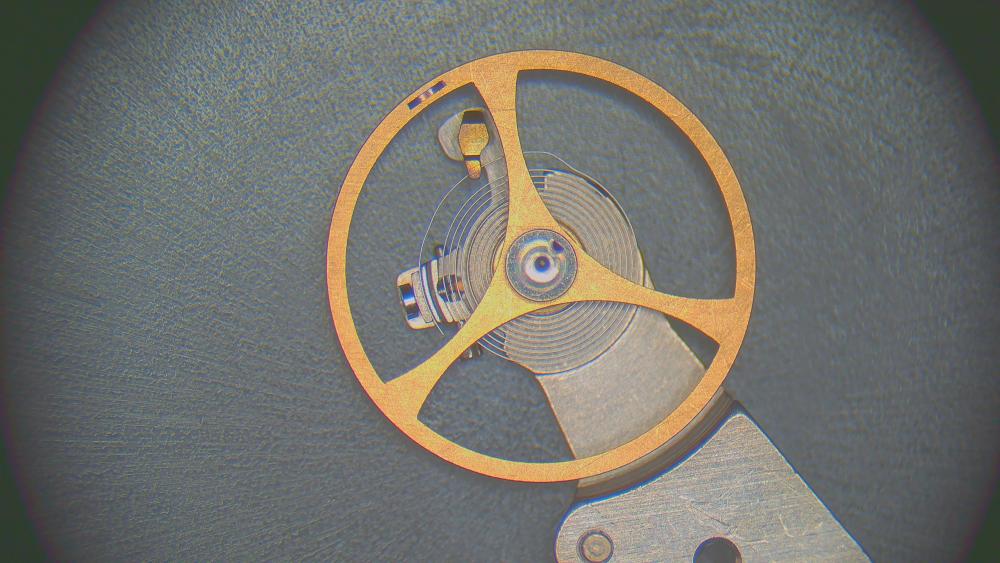
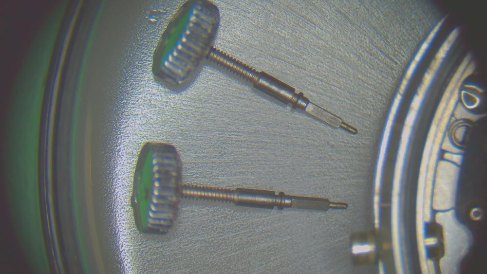
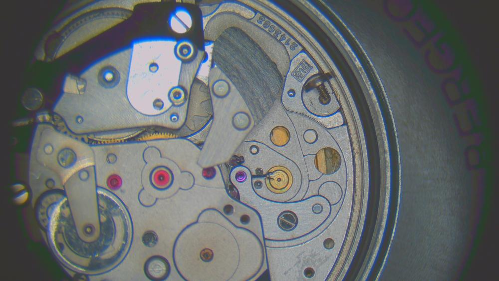
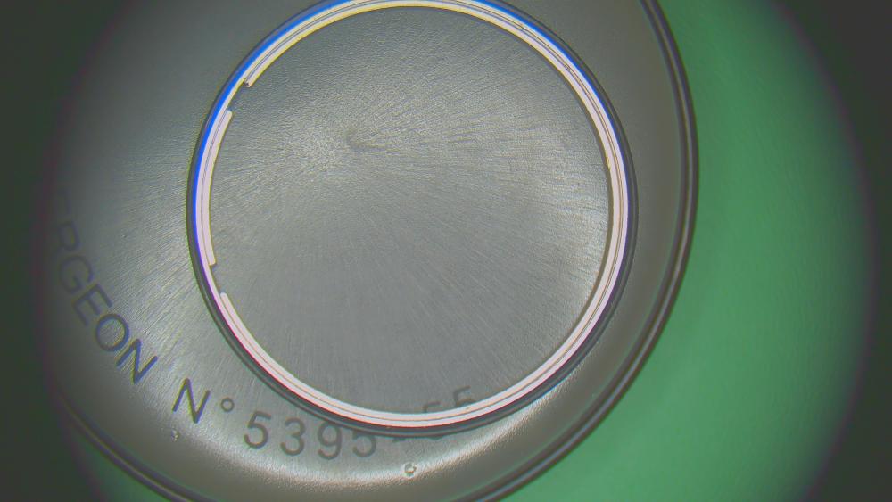
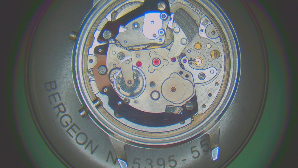
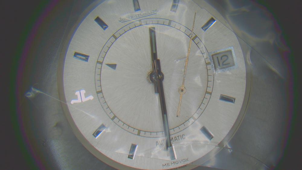
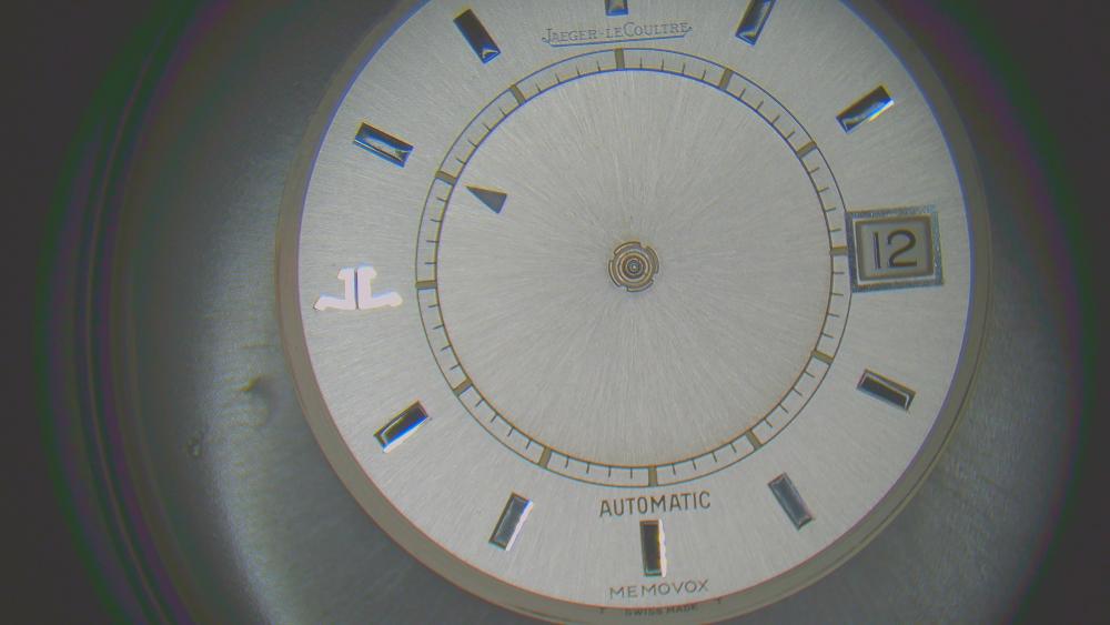
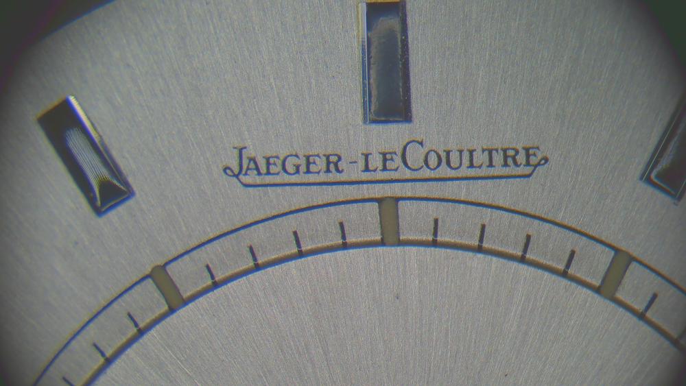
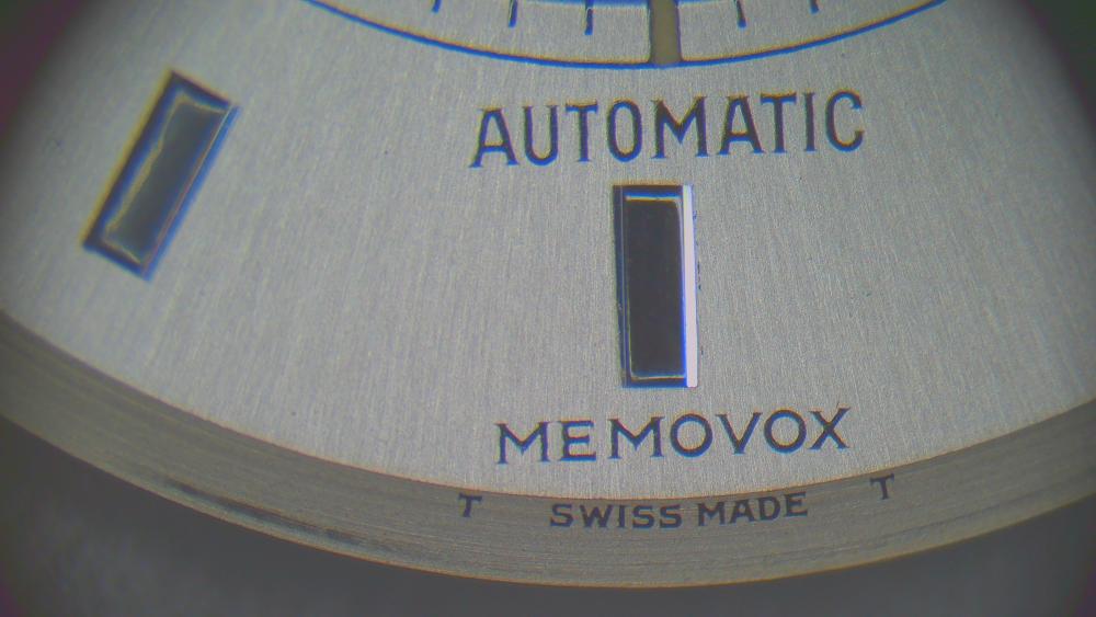
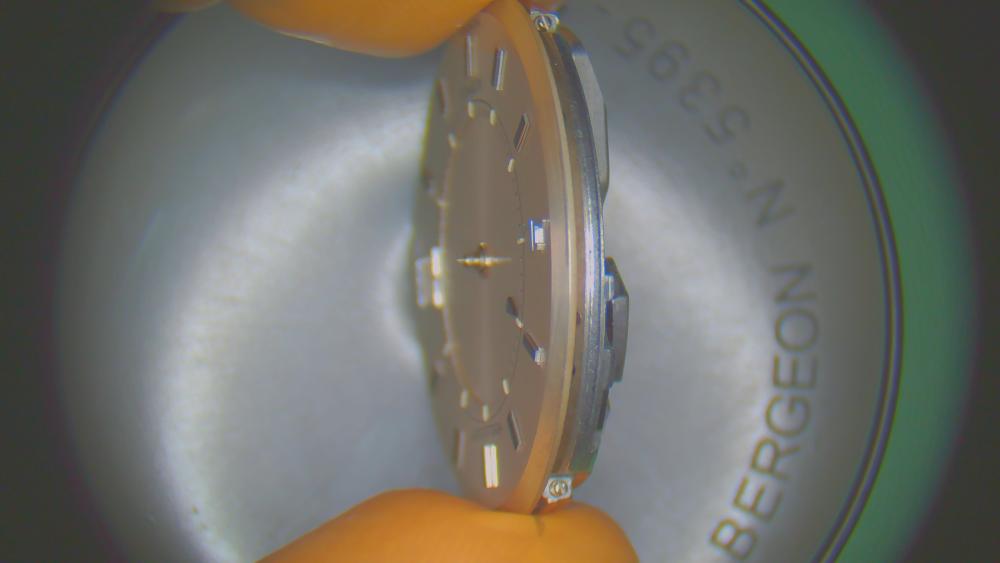
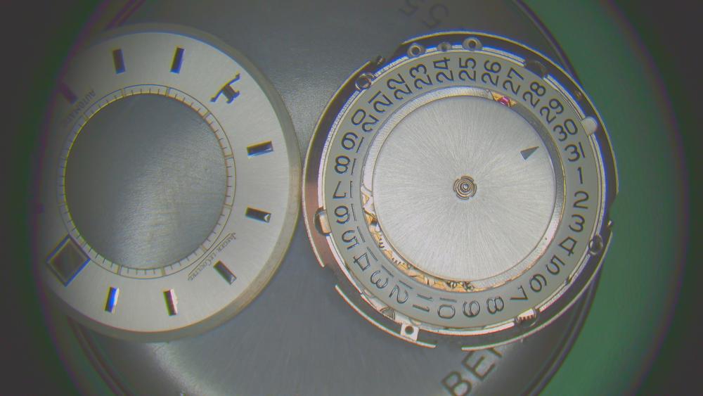
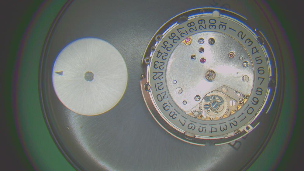
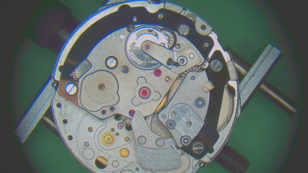
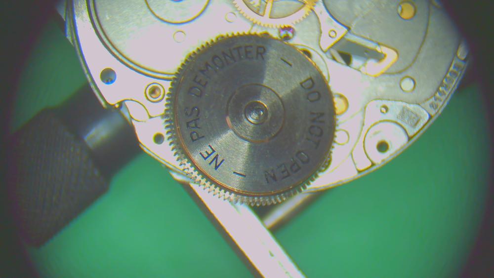
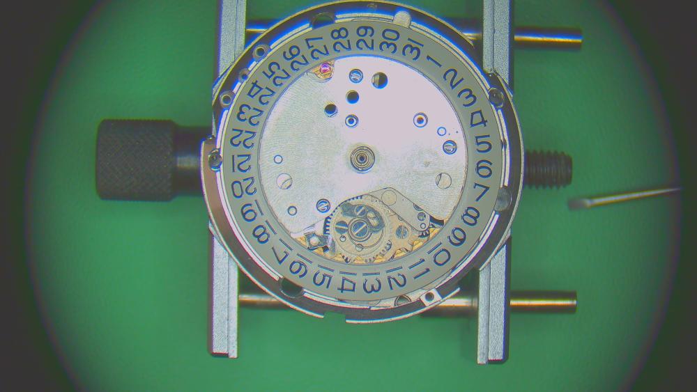
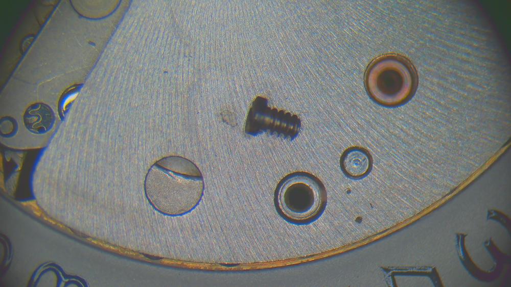
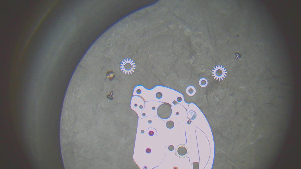
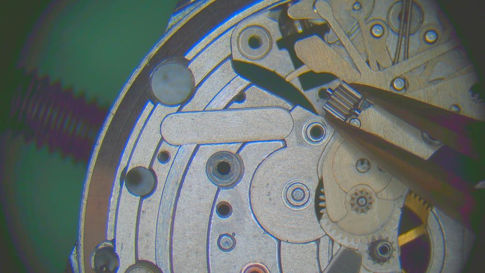
Hello everyone, this will be my first proper walkthrough and also my most complicated watch yet. A beautiful JLC Memovox E875 ("Speed beat") with calibre 916. This is the first of several posts: disassembly. You'll see my order of disassembly and close-ups of all the screws. Those are the main points. If there's anything particular, I'll write a comment. Otherwise the pictures are hopefully self-explanatory. Here's the beauty before disassembly: Ready to go with nicely dressed tweezers... also, screw slots are generally very thin so I also dressed all screwdrivers to very fine tips. inside of the caseback has a little knob that is hit by a hammer to create the alarm sound. Movement complete. before any disassembly, you can already see the magic level system of the automatic works I start by taking off the rotor. rotor underside rest of automatic works with three blued screws. magic lever system balance first.. identical stems. two case screws retention ring holds the gasket hands off and some dial-porn dial feet screws are nicely positioned so you can hold the movement in one position and access both at the same time. Thanks, JLC! both dials off let power down before this point! driving wheel for ratchet wheel / kinda-reversing wheel the alarm system train bridge I take the opportunity to remove the clutch wheelS and sliding pinionS. Again, both are identical. Nice. back to the train barrel can come out without damaging the center wheel. But careful. underside of the bridge with TWO crown wheels. NOTE: one "seat" is missing. Its absence has cause some damage to the bridge. I had indeed felt some resistance when winding the alarm barrel and it was one reason why I wanted to service it.. Part 414 is ordered from eBay. Barrel says "do not open". A whole other thread is devoted to this, see here: let's do the dial side: this spring was hard to get out. only an oiler would squeeze under it. the date wheel can stay assembled like this (no disassembly shown in the manual) previous watchmaker liked oil a lot. the alarm activation wheels lots of wheels.. also part of the alarm system pretty cool how the two keyless works are kind of the same and with some overarching parts damn, this spring was hard to get out. canon pinon and then the center wheel i remove balance jewels on both sides for thorough cleaning and reinstall the balance for cleaning. alarm barrel is normal (no "do not open"). the main barrel takes some nerves to open, but does so just fine. However, the edge of the barrel (where it holds the lid) is burnished a bit. I'm smoothing it out with the pointy end of a bracelet tool. This will allow the lid to go back in without problems. I'm planning on burnishing it over again when the new mainspring is installed. work in progres. done


 2 points
 -
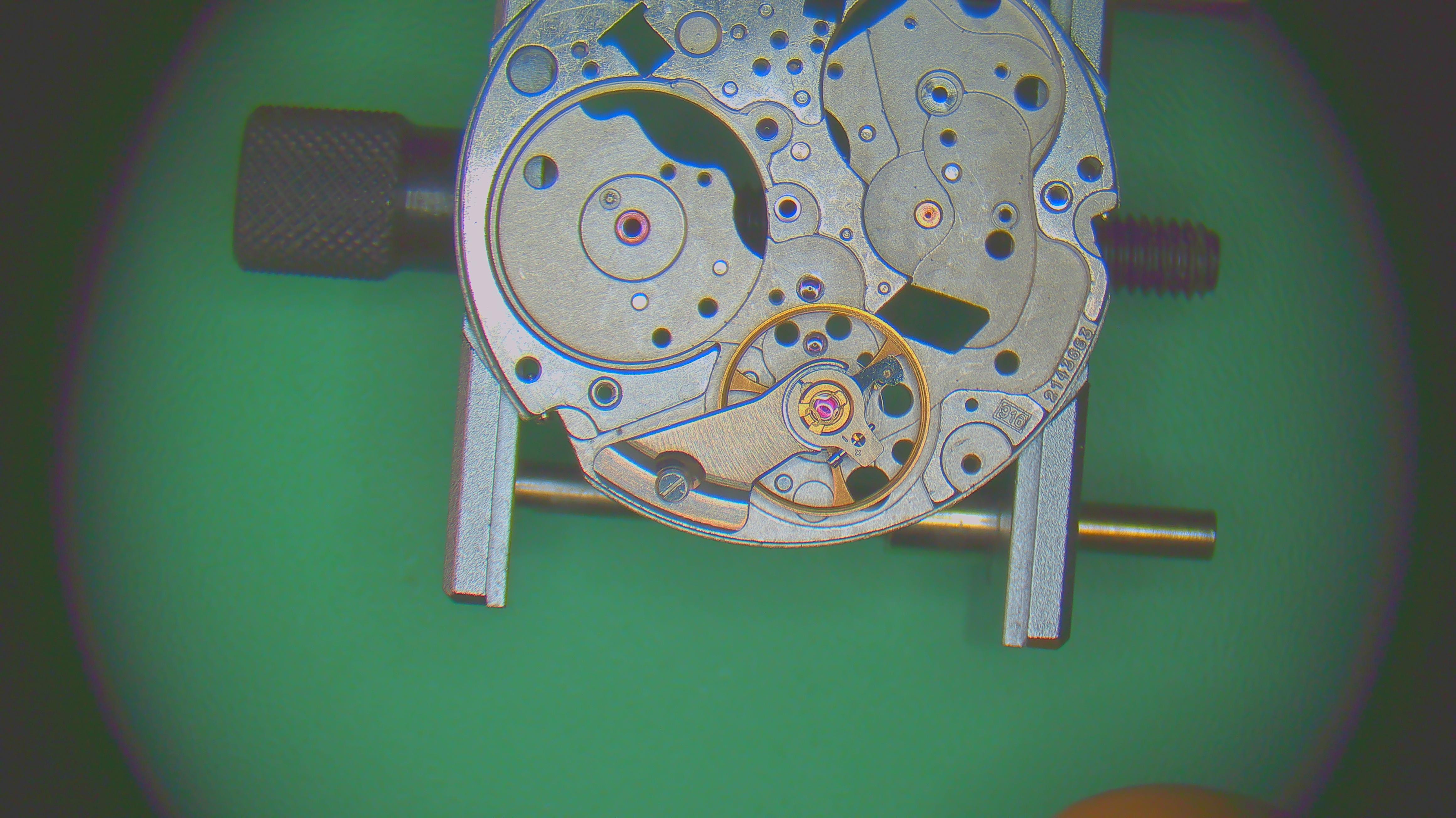
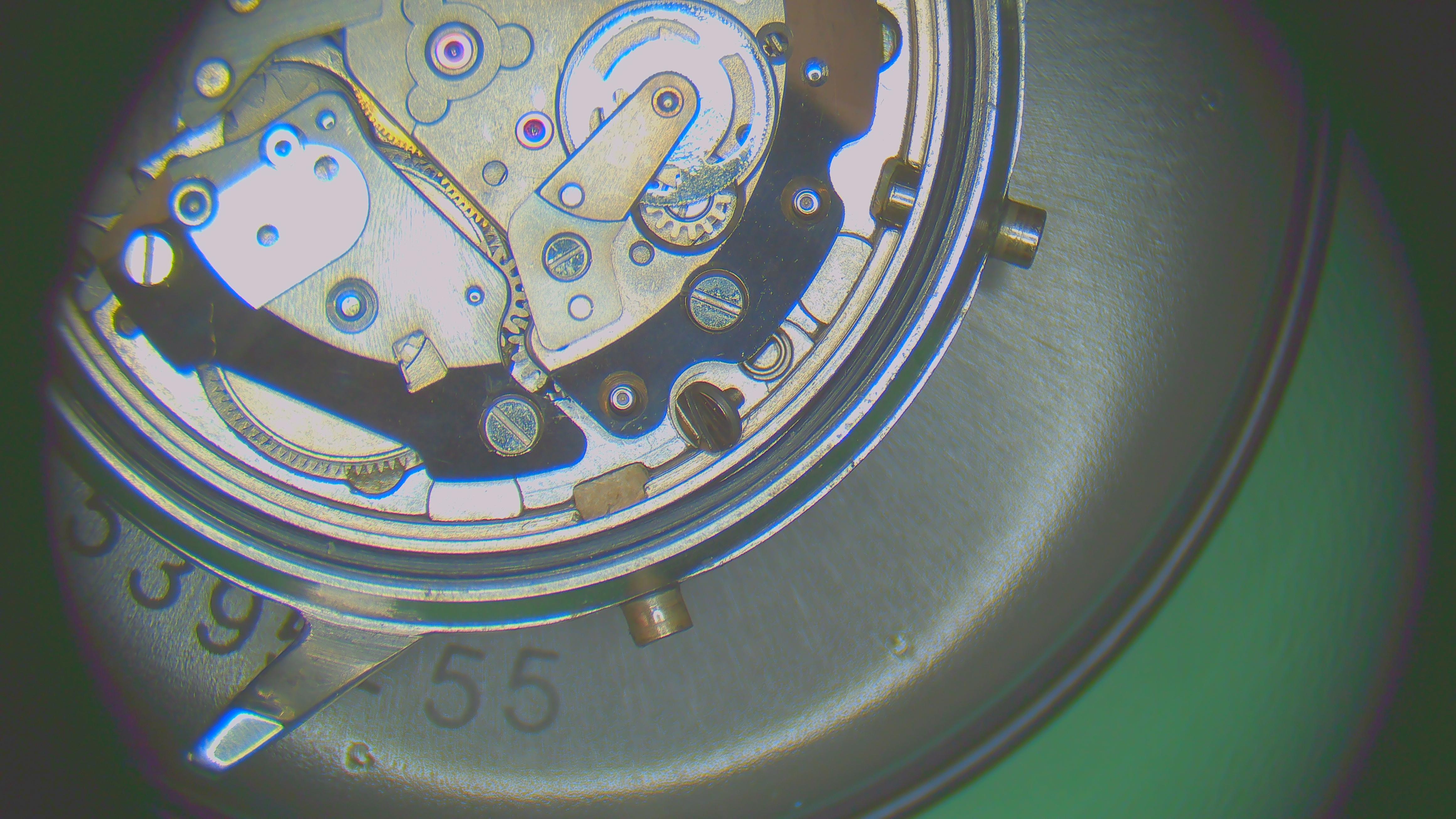
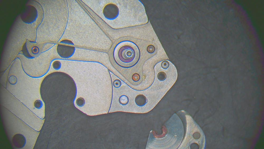
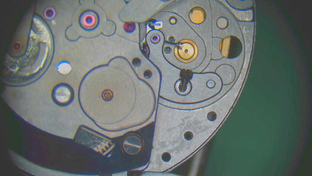
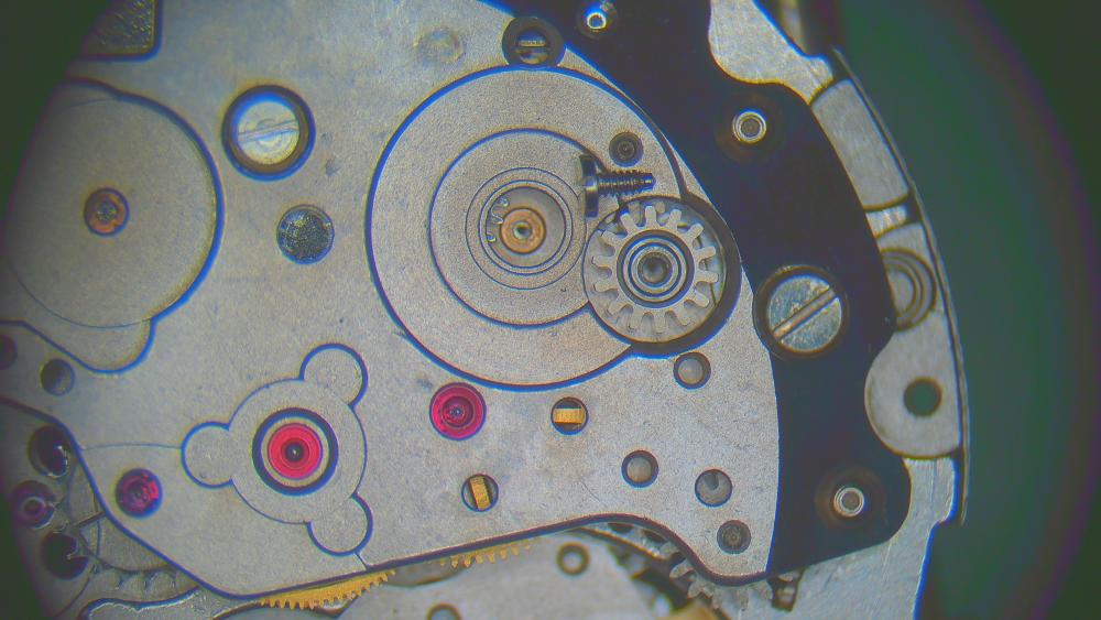
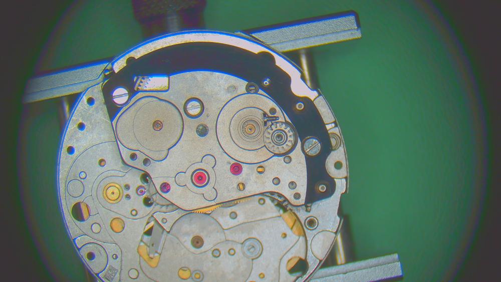
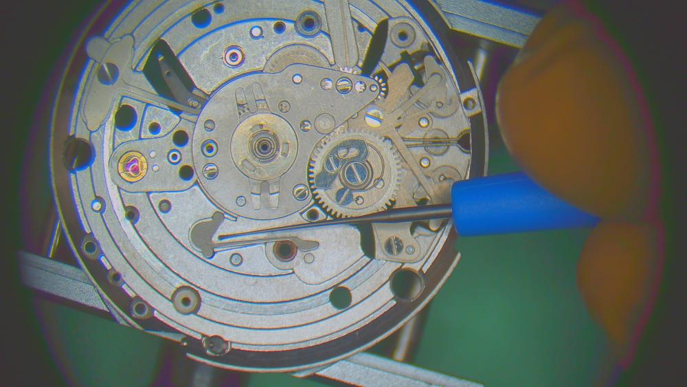
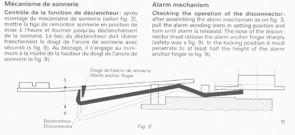
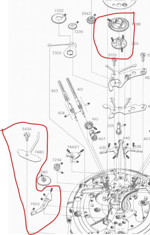
Hi @Khan, some more info would be helpful. Did it work before? Did you service it? Have a look at the manual for the cal 916 (I'm about to finish working on one). I think the alarm system is very similar to yours. https://watchguy.co.uk/tmp/JLC 916.pdf To see more, you need to access it from the dial side and under the calendar works. Here are a few key screenshots with highlights on the parts that are most likely your problem: ...and a picture of it assembled. You can see the "disconnector", which is the part you seem to be pushing down from the train side. It should normally be released by the two special hour wheel and the unlocking wheel (both in the center).
 2 points
 -
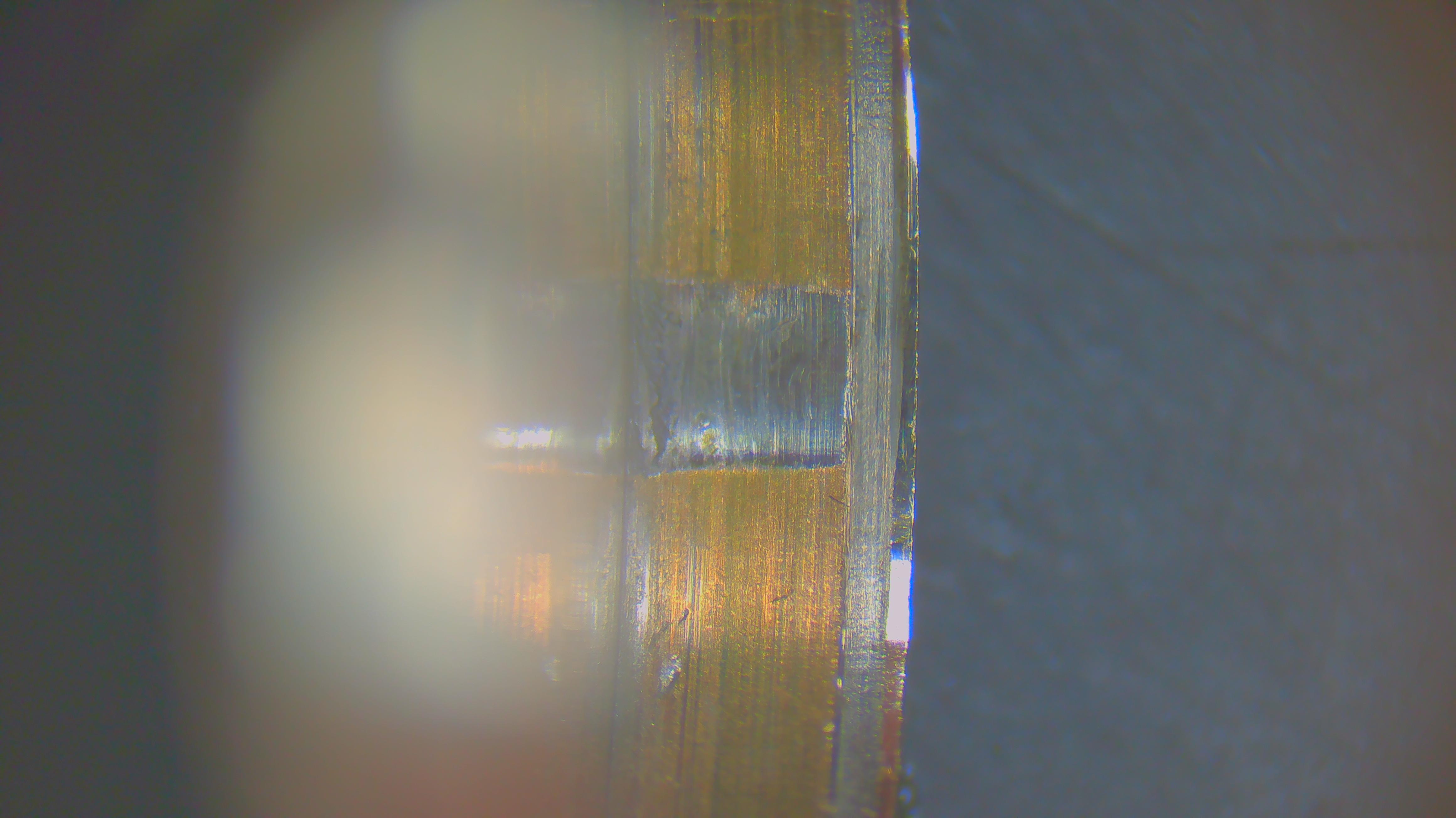
Hello friends, here's an update on this "interesting" barrel. First, a bit off topic, my technique of applying breaking grease (I have 8217). I apply a dot, then smear it gently in the direction where the bridle will slip. Rather than ending up with a couple of dots, I rather have a thin film all around. I see the risk that inserting the mainspring from the retaining ring would actually push down the dots to the bottom of the barrel and away from the wall. This risk is reduced when the breaking grease is already thinly spread out along the wall. Anyways, more a side-note.. Now back to the main topic. After inserting the mainspring and arbor, I use the basic barrel closing tool to click on the lid. As a matter of precaution, I use the tool upside down: I put the barrel on the flat bottom of the tool and use the concave side to push down the lid. I'm thinking that it may ever so slightly compress the lid (like inserting an acrylic crystal into a bezel with a press). May not do anything, but felt smart Once the barrel is closed without any problems, I burnish the edge of the barrel wall towards the lid again. You can see the process in the two pictures. No image of the final product, but I tell you: it looks nice.

 2 points
 -
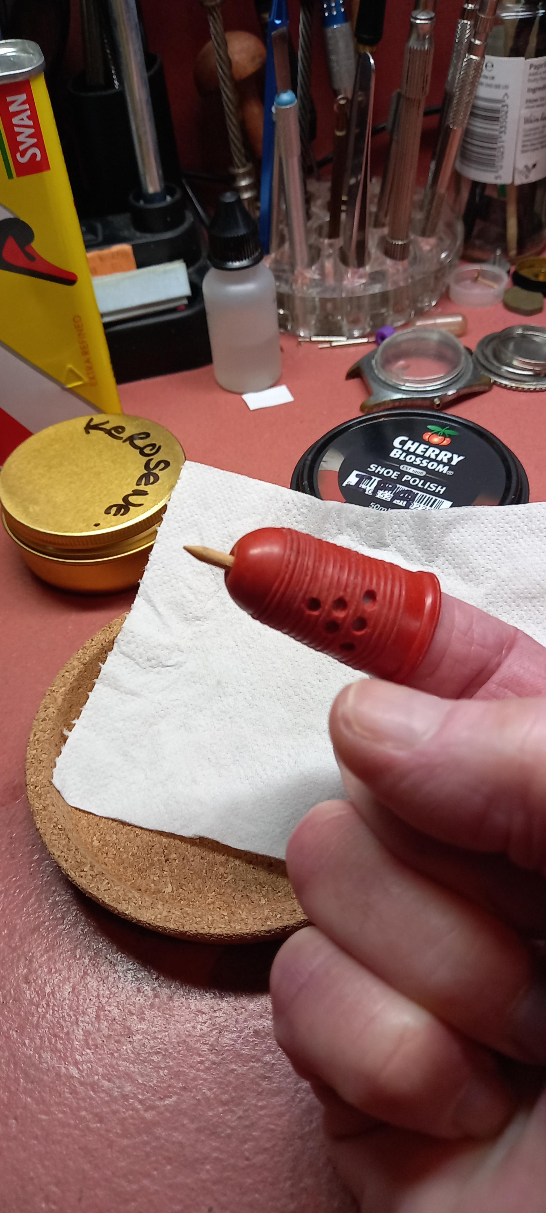
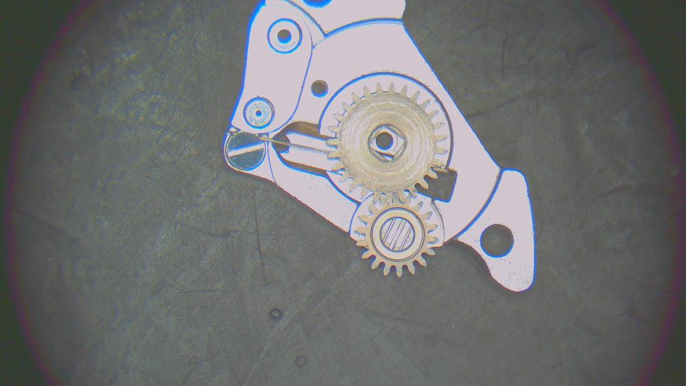
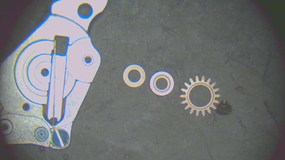
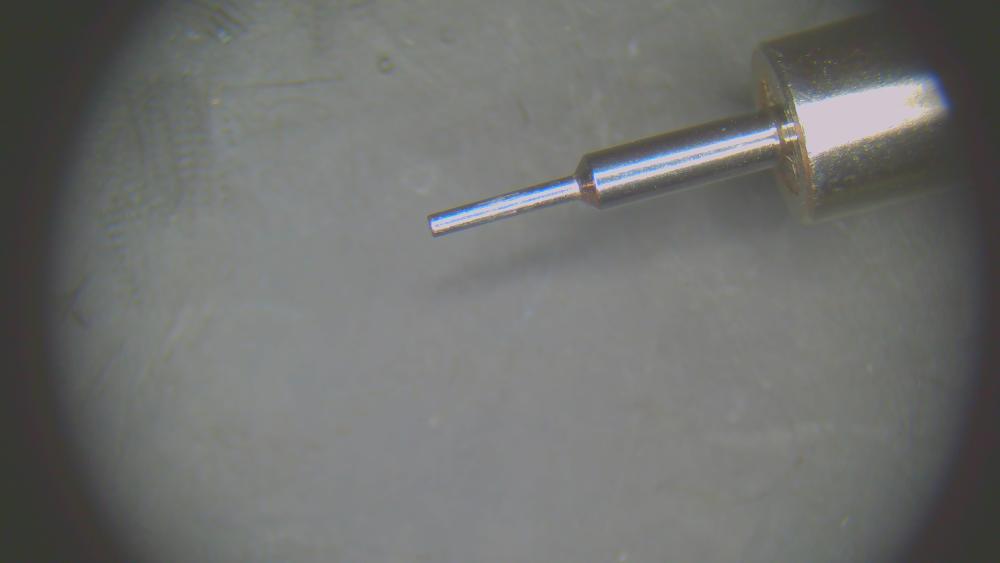
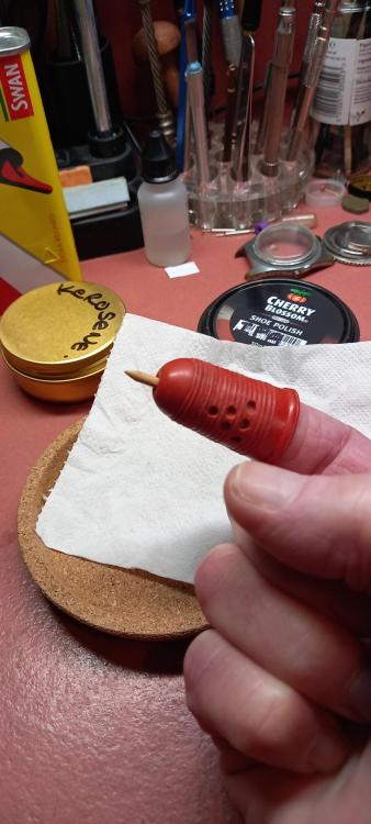
Some of these setting levers and variations of them are a push button release, the lever can have a tensioned bridge spring connecting either directly or indirectly over or to it. Kasper movements have them , the same situation of keyless binding up can occur with those as well. I like it rich, you'll be a watchmaker yet . Index finger shown can press the button and the thumb can flick out the crown. I was gonna show you the middle finger but thats just rude considering you had a good idea
 2 points
 -
A thimble with the pusher attached?2 points
-
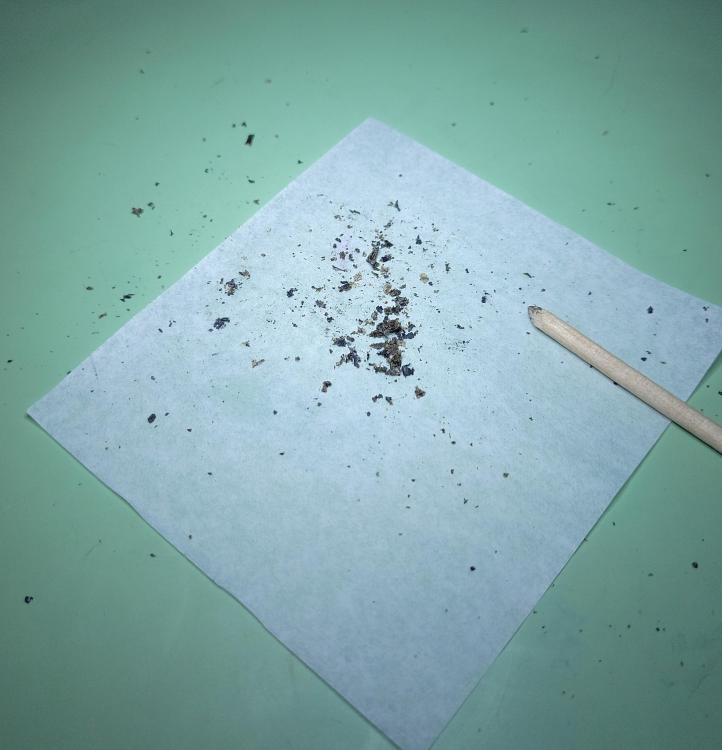
Looks like the stake was too wide to dome the washer enough before hitting the rim. I collect old stakes for just such situations, in fact i modified the outside chamfer of one yesterday to narrow it to better flatten out a staff rivet, you can never have enough stakes to modify.2 points
-
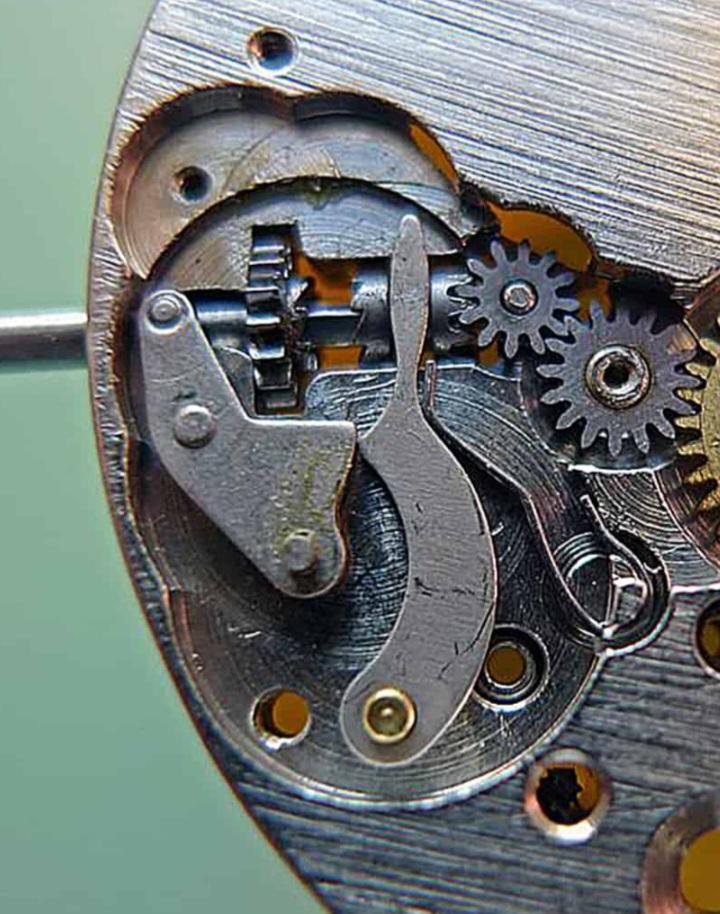
It can vary, look at this photo . Pulling the stem into setting mode the yoke spring gets tensioned and when the setting lever screw is loosened (traditionally in this example was called the pullout piece screw for obvious reasons ) to release the stem too much the yoke under pressure against the pullout can jump underneath it and not always re-position as it has lost interaction with the pullout piece's slider and the two parts can bind up and get stuck in misalignment causing maybe an unwanted dial off situation to re- align things. It doesn't always happen but it can do, in winding mode there is less pressure on the two mating sliding surfaces so the problem is far less likely to happen. Again it all depends on the keyless set up, but this one is a classic for it , if you are not careful, i make a mental note of how many turns to make on the pullout screw to just release the pullout from the stem also avoids you completely disengaging the screw . I now look forward to an onslaught of abuse for calling the setting lever the pullout piece, i think it suits better in this example of releasing a stem so there ppbbbbbbbtt.
 2 points
 -
Gotta love that arm cheese2 points
-
Nice job, I have that same watch (Senator 'F') and really like the look.
 2 points
 -
Get a decent set of basic tools. Read books about watchmaking, watch videos, or better yet, take Mark's courses. Ruin your first movement, service your second and repair your third. By that time, you should know enough to know what you don't know and what you're not comfortable doing.2 points
-
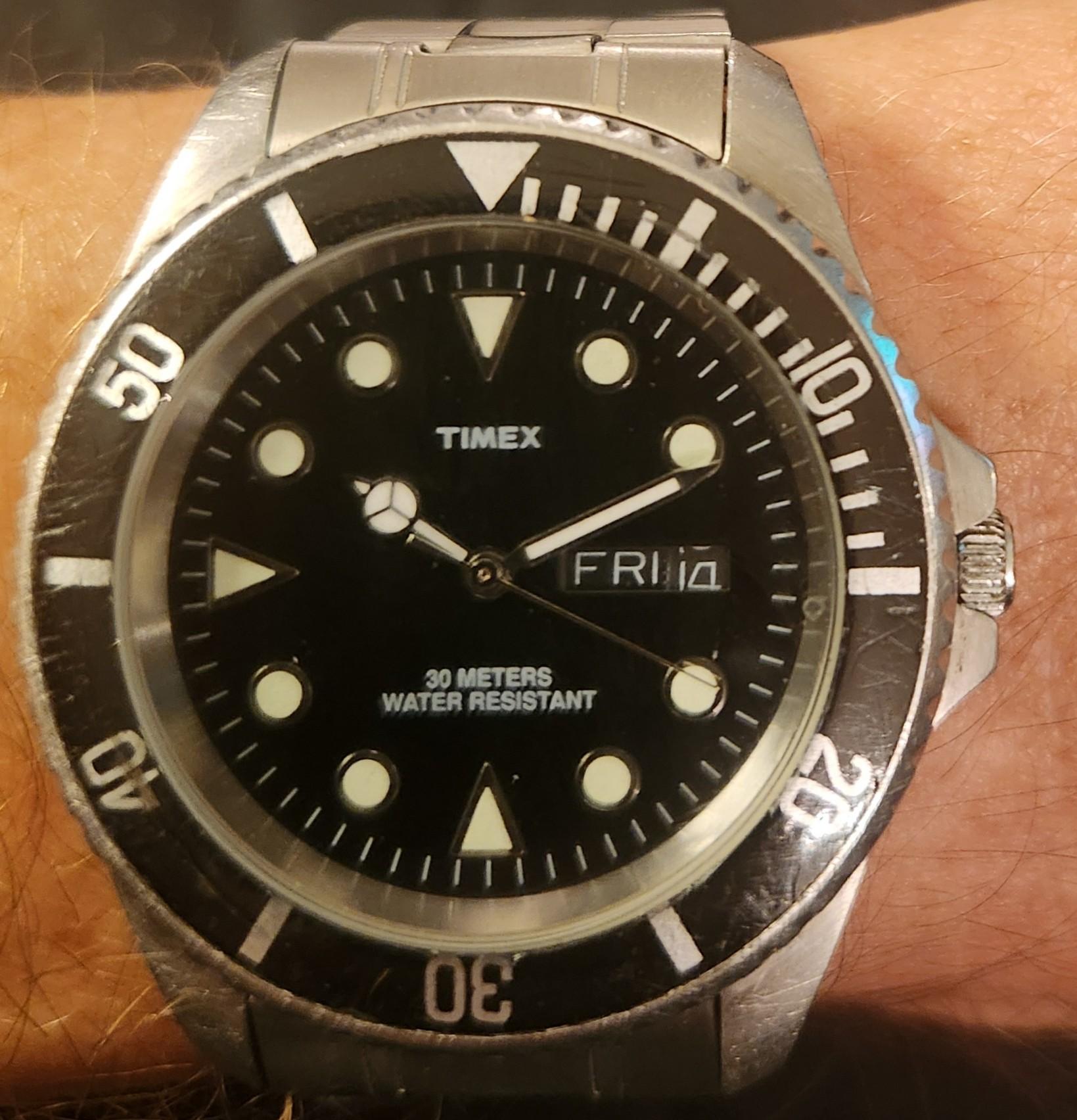
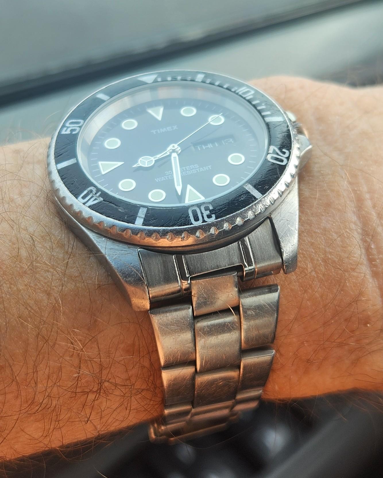
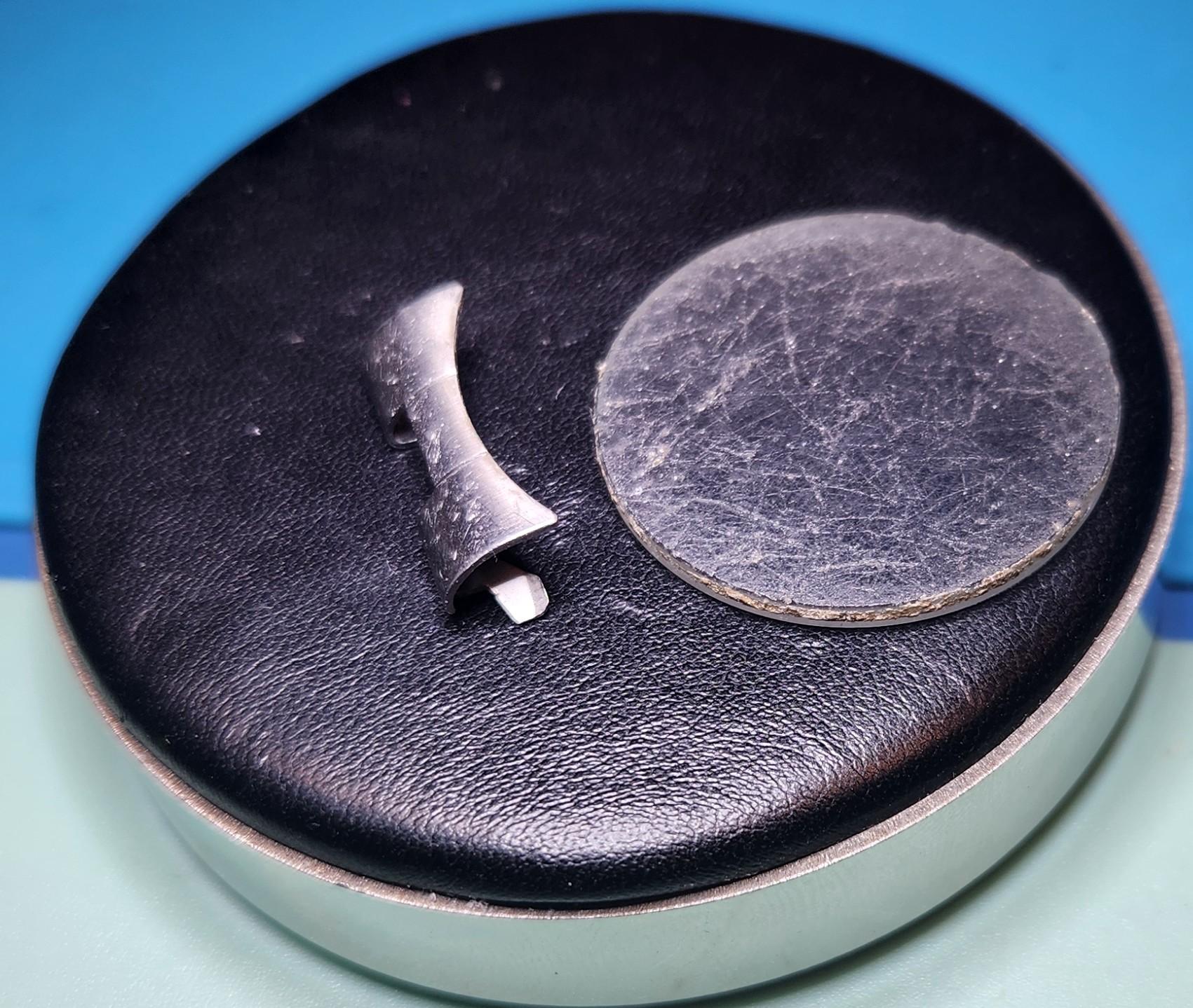
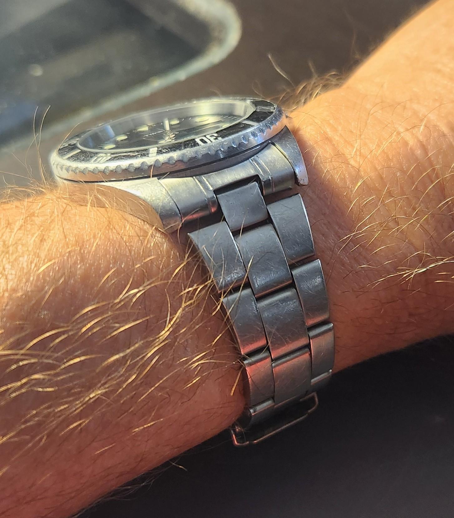
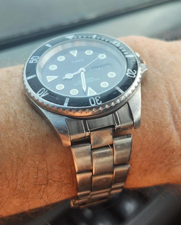
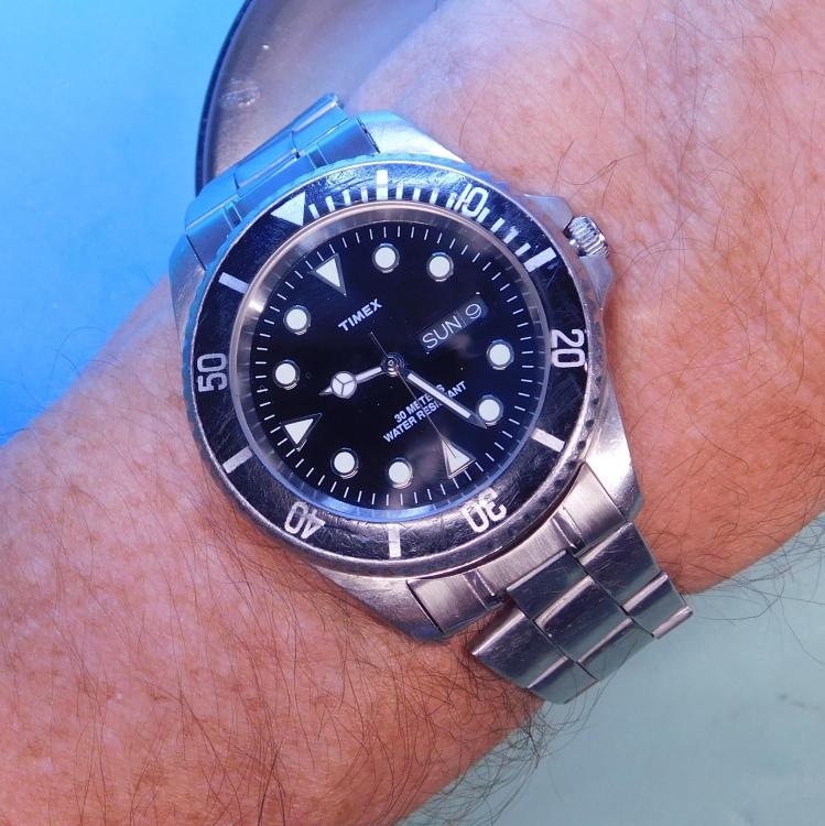
This is a quartz but one of my current favorites. Is 40mm and wears very nice. Was able to pick it up cheap and replaced the glass. Could not read the time!


 2 points
 -
this one is VERY nice. cool lugs. pie pan dial. what more could you want?!1 point
-
Thank you so much for the kindness.1 point
-
Good luck. You can see my full disassembly here (and I'll post the assembly in the next couple of days):1 point
-
It's been a while since I've looked at one of these but it sounds like the disconnect spring. Have you got the dial off as you should get a better view from their.1 point
-
There are still quite a few around, but you have to be patient.1 point
-
Does the alarm wind and set correctly?1 point
-
The plastic case ring probably has a couple of bosses on the movement side to hold it firmly in the case, but you should still be able to lift it straight out. Get yourself a pair of latex (or vinyl if you're allergic) gloves so you don't leave fingerprints on the movement. Hold the movement down and gently pull up on the case ring with a stout pair of tweezers something like what's shown in the following video.1 point
-
There are sites where with some information as advised by @RichardHarris123 you can narrow down the possibilities. https://watch-movements-archive.com/ https://ranfft.org/caliber/index https://17jewels.info/movements/1 point
-
Firstly the brand is very often unimportant, it's the caliber that matters, AS, ETA ect and the the caliber number. Eg AS 984, ETA 2824 etc. Most watch movements will have it stamped somewhere, on one of the bridges, under the balance wheel or under the dial. Some don't and then we have to play detective using the movement diameter, the bridges shapes and the keyless works. After that then you might find a parts sheet but not always.1 point
-
Parallel within the range of the hairspring's movement between DU and DD.1 point
-
Thanks guys. I did originally think of laying the movement on a drawing pin and pressing the face down but I then thought of a better solution, that is if you have a 3D printer. There is another thread on here where a guy (Thank you) has designed a modular 3D movement holder so I thought just print out the insert and make the inner diameter the same size as the dial. I used some flexible TPA filament and it worked like a dream I can lay the movement face down and press the pin, with no problem Sorry I'm trying to upload some photos but for some reason now my photos are corrupt
 1 point
 -
Try this https://web.archive.org/web/20230305223408/http://www.ranfft.de/cgi-bin/bidfun-db.cgi?10&ranfft&0&2uswk1 point
-
If there is any damage, which clearly there is because it was packed badly, then I wouldn't hesitate getting a full refund and returning it. I wouldn't 'make do.' This is a top grade movement worth many hundreds. If the seller is ignorant enough to send a watch movements this way, then it isn't going to go well for them.1 point
-
We have discussed this a couple of times recently, you need to be a right hand finger contortionist. It is possible to hold the dial in your left hand and press the button with a needle in your right hand while flicking out the crown with your right ring finger. Either that or a cup movement holder or a holder that just grips the edges of the dial not interfering with the hands.1 point
-
I forgot to mention and you may already know this but whatever oil you use for the ball bearing, you should apply a minimal amount. Otherwise, you risk inhibiting its free movement.1 point
-
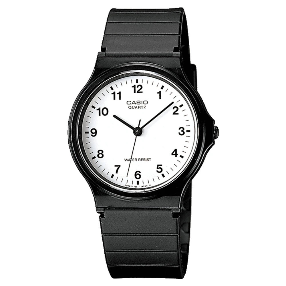
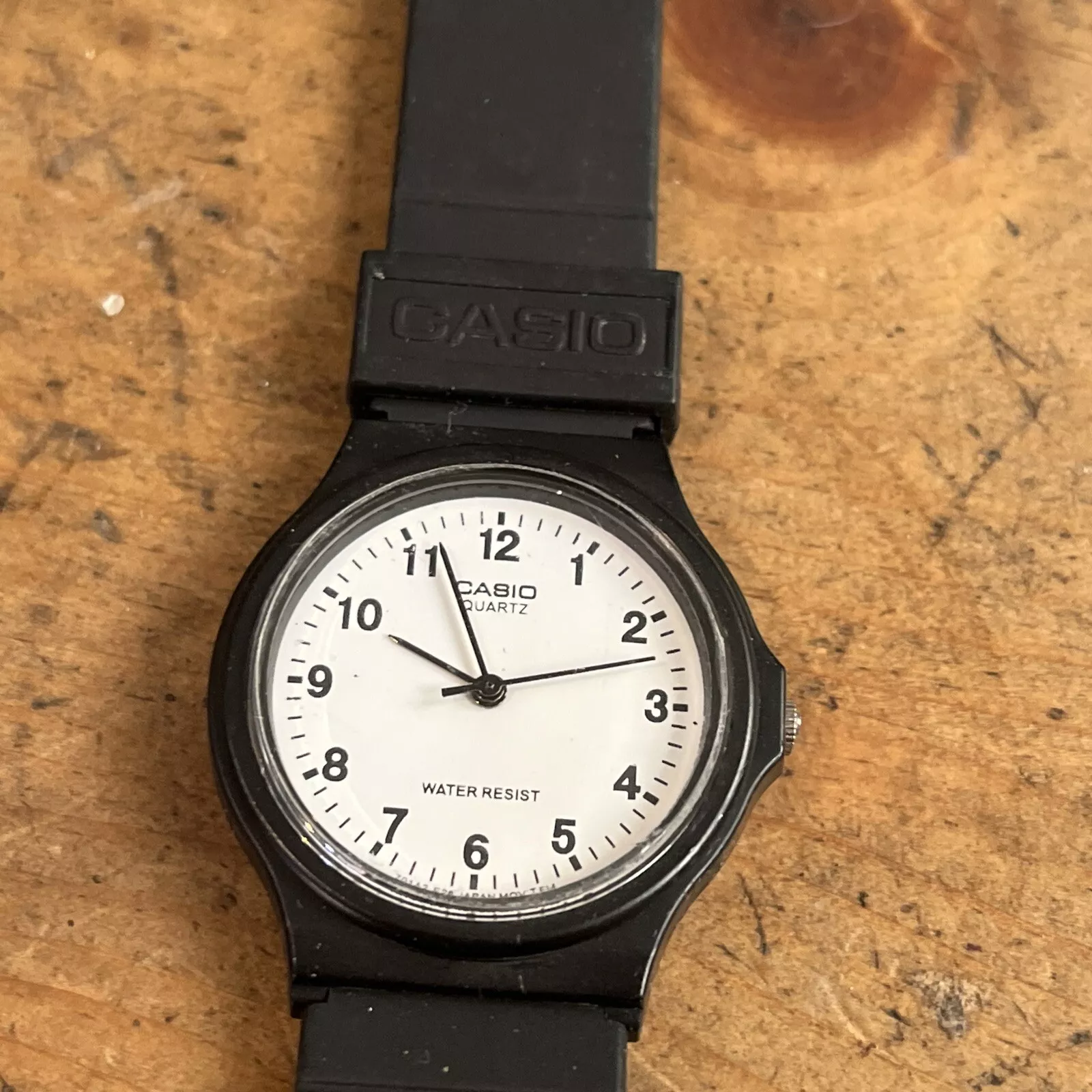
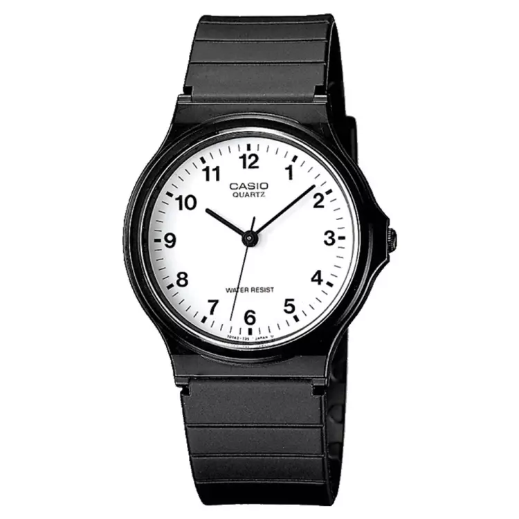
I had a quick look for a strap for the Casio MQ 24 in the previous post, and... picked up another complete watch for 0.99p
 1 point
 -
That's OK for removing the gasket but it will be difficult getting a new one in.1 point
-
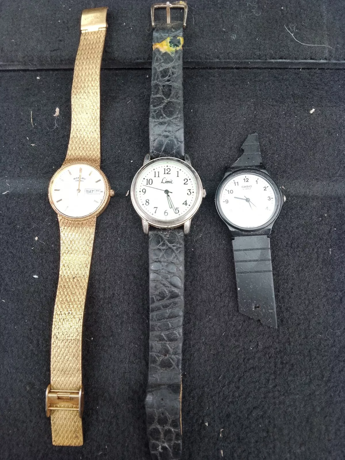
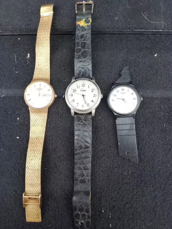
These little "beauties" are on their way. Who could resist three for a quid? Most sane and sensible people I suspect.
 1 point
 -
With these clocks dials movements and cases were all made separately. Dials could be sitting around for ages before being used the same goes for all that makes up a clock. The customer would ask for what he or she wanted the more you wan't the more you had to pay. In it's time this was not a cheap clock to have made. Solid brass dial strike / silent. Other things such as what was the in style at that time. Longcase clocks from London and the surrounding area were far ahead in dial and case design then clocks from up north or south as much as ten years. It's still the same today London is the centre of things and again cost. In counties and places out in the sticks if you had problems in fixing mechanical things you went to your village blacksmith because every village had one. So I would say the blacksmith you have found had something to do with this clock. He might have just been the person who put the movement together. I gave it a latter date because what I can see of the movement the wheels have been cut by machine and not by hand, also it is made of brass and not cast brass.1 point
-
for the suspension spring, it is only important to choose one that will bring the rod on which the pendulum is hanged (it is not shown on the pictures) to the correct position in height. And, of course, to fit the slots in the rod and anchor bridge. Richard didn't mean at all that the chain He mentioned has something to do with the calendar. He ment a fusee chain, if the movement was a fusee one. Well, it is not fusee, and is not spring driven at all. So, forget about the chain, no chain there. If You need to know what is missing in the calendar movement, then show pictures of the wheels under the dial. The calendar wheel is not moving constantly, it is shifted once per night, the shifting takes some time - about half hour or similar. So, the calendar wheel is not just meshed with the other wheels. For sure, there must be a day wheel there (it will make one full revolution per 24h) and there must be a pin on this wheel, that will shift the calendar wheel one tooth ahead each night. There must be a jumper that will fix the position of the calendar wheel when the pin is away. The day wheel is (usually) driven by the hour wheel, and the ratio is 1:2. But sometimes watchmakers used different designs, where the day wheel is not dirrectly driven by the hour wheel.1 point
-
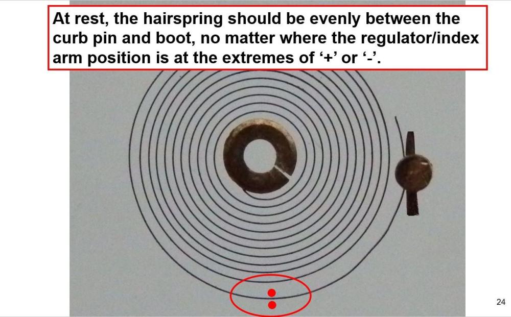
Not the misshape of pin itself, but should straighten it Here, with the oscilator at rest, hairspring must come to rest at midpoint of pin-boot. Good luck fixing your watch.1 point
-
Since posting that thread, I've come across a couple of crowns that the washer did not come off. I think it has to do with the width of the ledge under the washer. If the ledge is too wide, the washer won't dome nicely. I'm currently working on an idea to grip the inside of the washer and pulling the washer out of the crown, something like a internal bearing puller.1 point
-
Nice work! I just finished a Sea King with an 11AOACB movement, and it's definitely an interesting one.1 point
-
Thing is the terminal curve is shaped so that the regulator can track it from both ends of it's range. Some of these that look like an untouched raw spring are still spiral shaped and often dont have enough room between the first and second coil next to the curb pins. Sure the first coil can be pulled out but the pins may not track it's non concentric last coil and need more adjustment . Still curious to know how differently end curveless springs perform without the double bend. The curb pins are something that get knocked about a lot. To fully straighten it out it would be removed and rolled between flat steel. There could be some rate variation between DD and DU if the pin was badly damaged and the pin spacing varied a lot from one position to another, more noticable at low amplitudes, the pins should be as parallel as possible. It's not something i get over worried about as long as the frequency rates stayed at that point on the hairspring1 point
-
Yep ive tried a Proxon micro drill, a kind of posh accurate dremel using a diamond disk and freehanding the staff it was way harder than the lathe. I caught the balance wheel several times. That idea might be ok with some sort of feed. You need high magnification for doing this even with my big boy microscope at x40 i felt i wanted more. You will be using your staking set for a lot more than punching staffs out. I thought about this a while ago Andy, with a diamond burr to grind off the hub.
 1 point
 -
Be interested on an opinion from a lathe user as to how much you would need to spend to get something that with practice would do the job?
 1 point
 -
Ha, like OH I have 4; just weighed my most used one and it's 30 grams with the (lightweight) handle, so right at 1 ounce. There's a smaller one, and two larger. Again like OH the biggest one gets used for clock work and comes in at 55g.1 point
-
I'll give it a try an let you know I would follow their recommendation. Oiling correctly is often an underrated art with far greater consequences than most people realise. I don't think it's a coincidence that JLC recommends 941. That said, in this particular case, I think you can safely use 9010 if you don't have or don't want to invest in 941. I've accumulated quite a few lubricants for that reason... but in this particular case I'm a bit hesitant. I understand that 9010 is a much older oil than 941. I guess JLC has found through practical experiments that they get marginally better results with 941 for just the rotor bearing, but who knows? Yea, I really wonder. What's interesting, is that for calibre 918 (introduced in 1994), which seems to have the same rotor construction as the 916 (introduced in 1969), JLC recommends "immersing [the oscillating weight] in a mixture of benzine and 0.02% D5 oil" (is that basically what Lubeta V106 is??). So they didn't stick to 941..1 point
-
Been there. Worn that Tshirt. I now have loads of watches, in bits. I made the mistake, as many do when starting, of obtaining cheap watches. I will learn to repair them I thought. Should have started my course ealier and learned that if a watch is working, you can do a service. If is is broken, unless you have massive skill, it will still be broken. You need replacement parts. Hey another watch that is broken will do. Not. Hence all the bits. I learned from Mark's course. I can now do full sevices easiy. Everthing except Shellac repair. Deep repair is specialist.1 point
-
Finally got around to having a dry run with the original roller that came with the watch and what should be a genuine nos staff that does match the movement caliber specified as an AS 554. No go at all , the bottom of the big table sits directly on top of the fork. So it seems the complete balance assembly has been modified to fit a staff that was made to fit inbetween the plate and cock. Unless I've gone wrong somewhere and identified the movement wrong and the staff should be a different one. Problem is the original staff broke in two and is very poorly made making it difficult to measure. Looks like this will have to be shelved until another 554 comes my way, or if anyone has one and can verify the staff measurements for me. Now i think about it I do have the stem, i could use that it check the caliber1 point
-
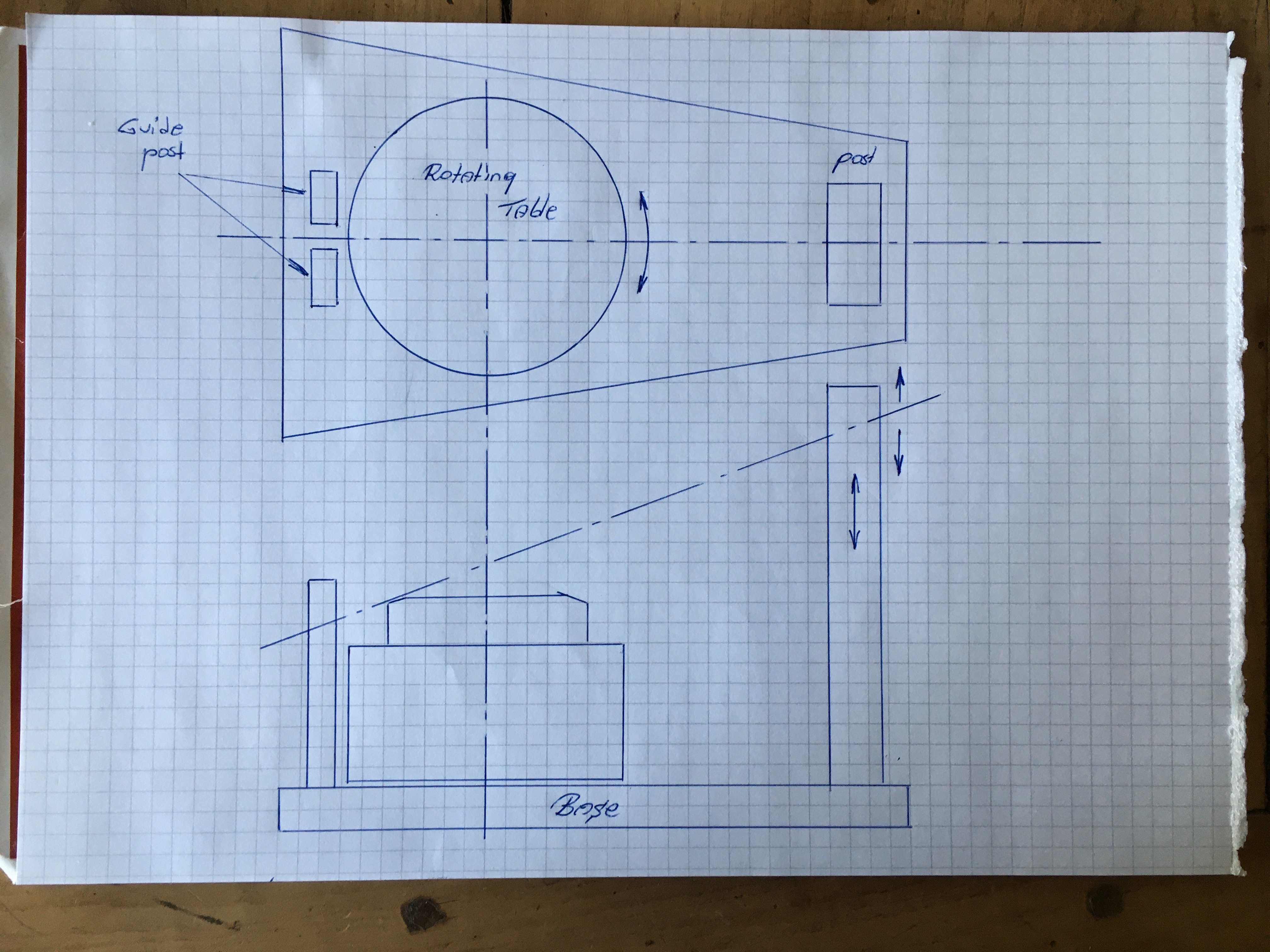
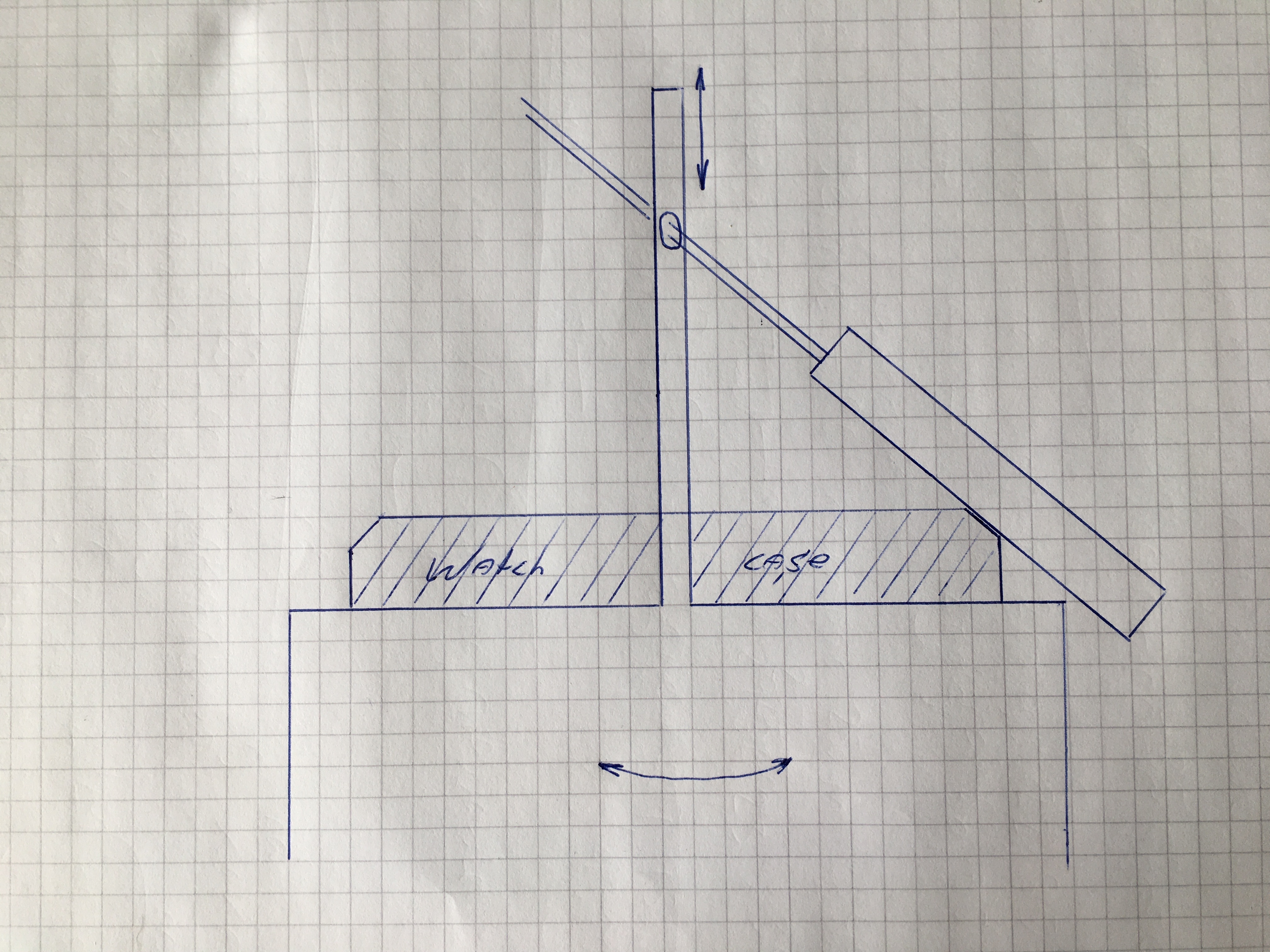
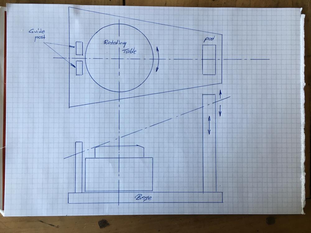
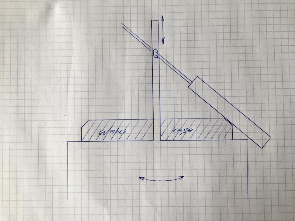
I had another idea, still based upon the "Lansky-principle", but perhaps more simple to build? Forget about the scale and proportions in the sketch, it's just to convey the idea. The center-post in the previous drawing doesn't have to be in the middle of the rotating table, it can be moved to somewhere else on the jig. What is important however, that the file runs through the center of the rotating table and through the center of the watch case. One side of the existing guide post in your current design can stay, it will make sure that the file stay in line with and directly over the center-line. The now moved "center-post" has to be adjustable in height (telescopic?), so the angle of the file (with a rod-extension) can be adjusted to the correct angle of the "to-be-sunbursted" surface. The rotating table has to be able to rotate, with or without a smooth running ball-bearing, but it is very important that the table is stable (not allowed to wobble) and stays in the center. The file used can be extended with a smooth rod, running through a hole, or a slot/slit, in the in height adjustable post. The width of the slit between the two guide post should be wide enough the accommodate the width of the file, but not much more than that. One thing vintage watch collectors-freak out about is when the shape of the case is altered, or previous sharp edges are rounded due to polishing. For cheap watches this is not a problem. I'm looking at Sunbursting an Omega 1975 Speedmaster Mark II case, so that has to be as precise as possible. Of course, it's a DIY tool, never matching the professional ($$$$) equipment, but since we are in the design phase, we may just as well give it our best shot Once the concept idea is established, dimensions and angles can be determined. Still hanging in the air is that little pesky problem of how to fix the watch-case in the center of the rotating table. Most watch-cases do have a circular inside, which seems to me a more sensible approach than clamping onto odd outer-shapes. I'm sure that there are some very bright minds on our forum who have some simple & smart idea's how to centralize and fix the watch-case. I do hope that they will chip in ! What do you think?
 1 point
 -
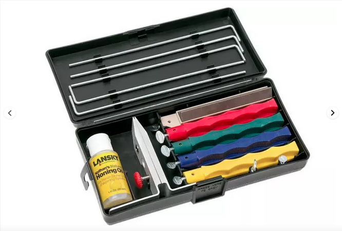
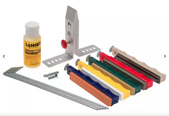
I've been contemplating a design, but never got any further than that , which is based upon a Lansky knife sharpening system, which I own for keeping our kitchen knives (razor) sharp. It's basically a clamp which clamps onto the back of your knife. Both "legs" of the clamp (on either side of the knife) do have equal degrees holes which allows you to sharpen the knife-edge, on either side, to a desired angle. Different grits grinding stone can be attached to a rod, and the smooth rod slides in the clamp-hole and the grinding-stone rest on the knife's edge, assuring a constant angle. There is a commercial (bla-bla-bla) video on Lansky's website: https://ad.knivesandtools.eu/en/pt/-lansky-professional-sharpening-system.htm so you get the drift of the system. For knives this system work excellent. The whole idea is to keep the grinding stone at a constant angle to the to be grounded surface. Now I'm just brain-storming; if it was possible to make an in high adjustable center-post (which would act as one of the Lansky's clamp-legs), the angle of the grinding stone can be seamlesly adjusted and set constant. Either the center-post has to be able to rotate, or as with your design, the table or anvil has to be able to rotate around the center-post. I made a quick and dirty sketch for the basic idea; If the table (or anvil) can rotate, the center post could be made of a threaded rod, "fixed" to the jig, but you have to be able to adjust the height (to obtain the correct angle) and to lock it in place (with a counter-nut?). Perhaps a higher base of the jig with a nut for the center-post included? This still leaves the centering and fixating of the housing Also, my idea is an inconclusive expansion on what I already have, namely the Lansky grinding stones. But even the coarsest grinding stone in my set, is too fine and too wide for a sunburst. It has to be a needle-file, but with a smooth end so you don't wear out the hole in the center-post. Feasible of just wishful thinking? EDIT; what if when you clamp the housing from the inside ?? Kinda a head of a lathe? With a 3-claw lath-head you can clamp on object inside the claws, or you can clamp a hollow object with the outside of the clamps. Of course, in a lathe head, all 3-claws are moving simultaneously, ensuring centrality. EDIT EDIT; One could perhaps also have a fixed center-post, fixed to the jig, and make the table adjustable in height (with shims underneath the bearing?)
 1 point