Leaderboard


Popular Content
Showing content with the highest reputation on 09/27/24 in Posts
-
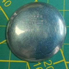
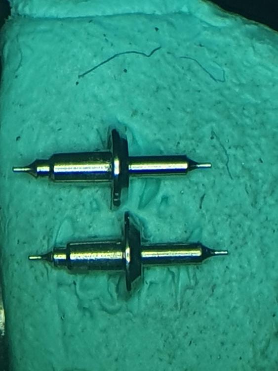
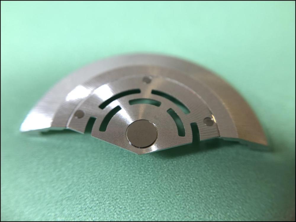
A little over a week ago I tried making something resembling a balance staff for the first time. It wasn't for any specific watch, just trying to get a feel for how the gravers and steel "worked". I got encouraging feedback , so today I decided to try again. Now for an actual project, a Junghans J47 with both balance staff pivots broken. I do actually have some new balance staffs for this specific movement, so that made it easier to get good measurements. I won't ask you to spot the differences between the DCN staff and mine (my wife sometimes says I'm snotty enough already), but any feedback is greatly appreciated.. Tonight I'll fit the wheel, finish the pivots on the jacot tool and see if it will actually work..
 2 points
 -
Nice! When I make a staff (just did another this morning) my "test" is does the balance stay still (no hairspring) when gently twisting the movement holder on the bench. Like ice in a glass of tea. It's not scientific but after all these years I can tell by how it behaves if it needs a few microns off the diameter or something.2 points
-
Without knowing that exact car, I'd check the connectors to the steering unit to ensure they are clean & no corrosion or anything loose. Also check the fusebox & battery connections etc. - electric power steering takes a lot! of current (it's fused at 120A on my Mondeo). Any corrosion or bad connections / bad grounds could cause faults. On the mechanical side, check the rack end boots & column seal, any bolt-on part of the steering unit; anywhere water could get in or oil/grease escape. The boots could just be rotting with age. If the boots have failed it could be full of water from general tyre splash, causing corrosion & wear.2 points
-
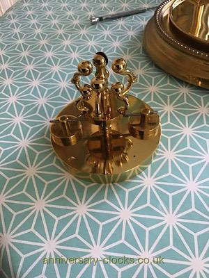
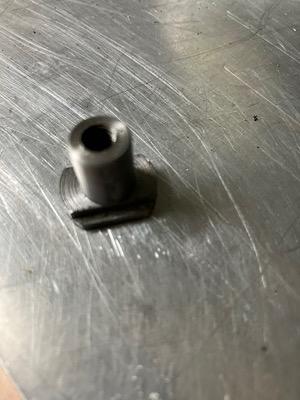
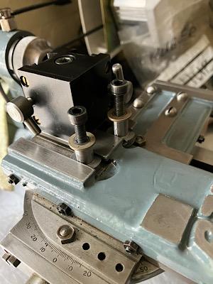
I have to make a couple of replacement pendulum regulation rods ( see first picture ), approximately 86mm long with 33mm of 6BA thread right hand thread one end and left hand thread other end , the problem was although I had a fixed steady that I made a few weeks ago I needed a travelling steady but I have never seen one all I had was a picture but although it is not exactly the same as the original I think is will do the job. Dell
 2 points
 -
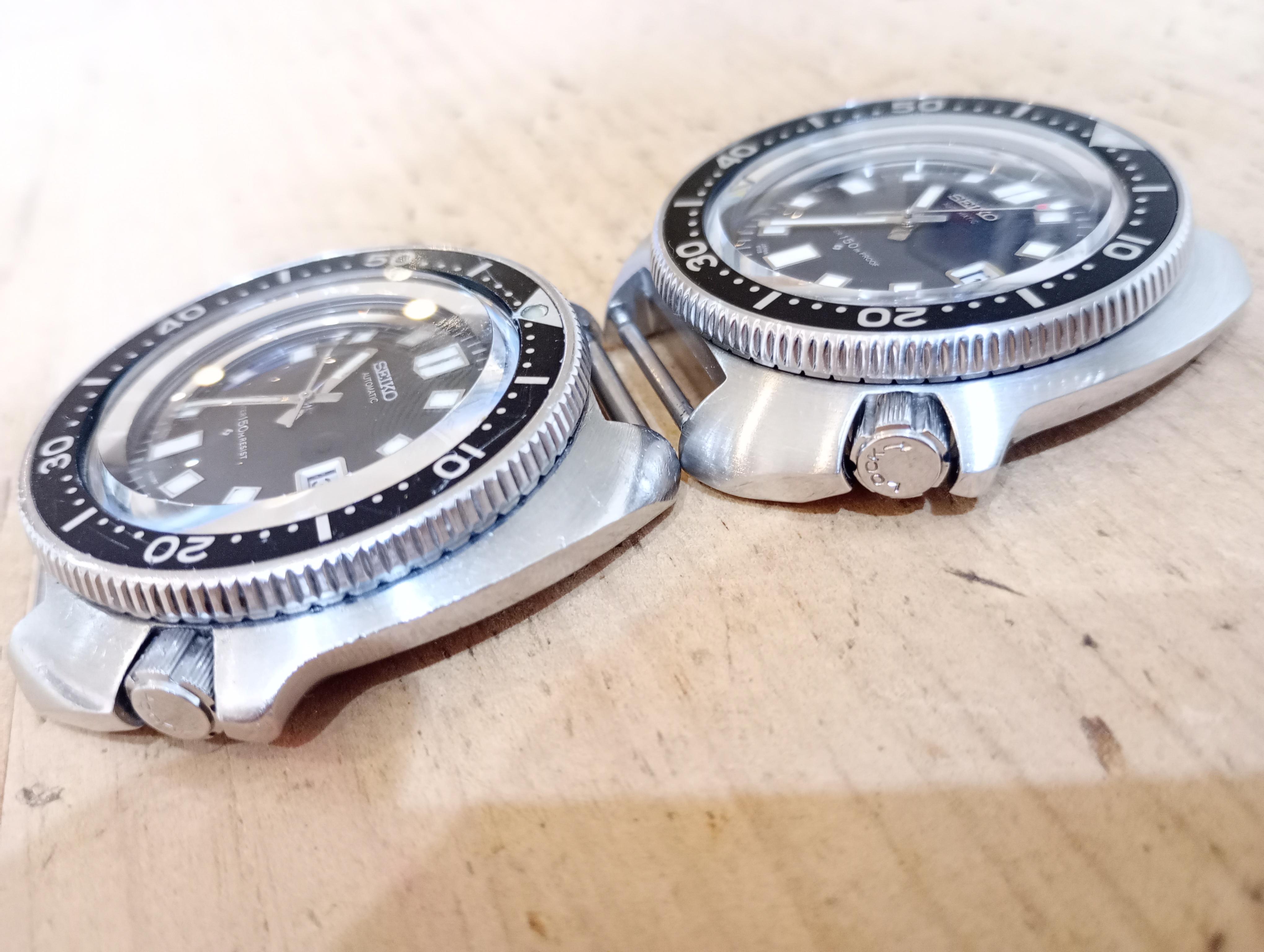
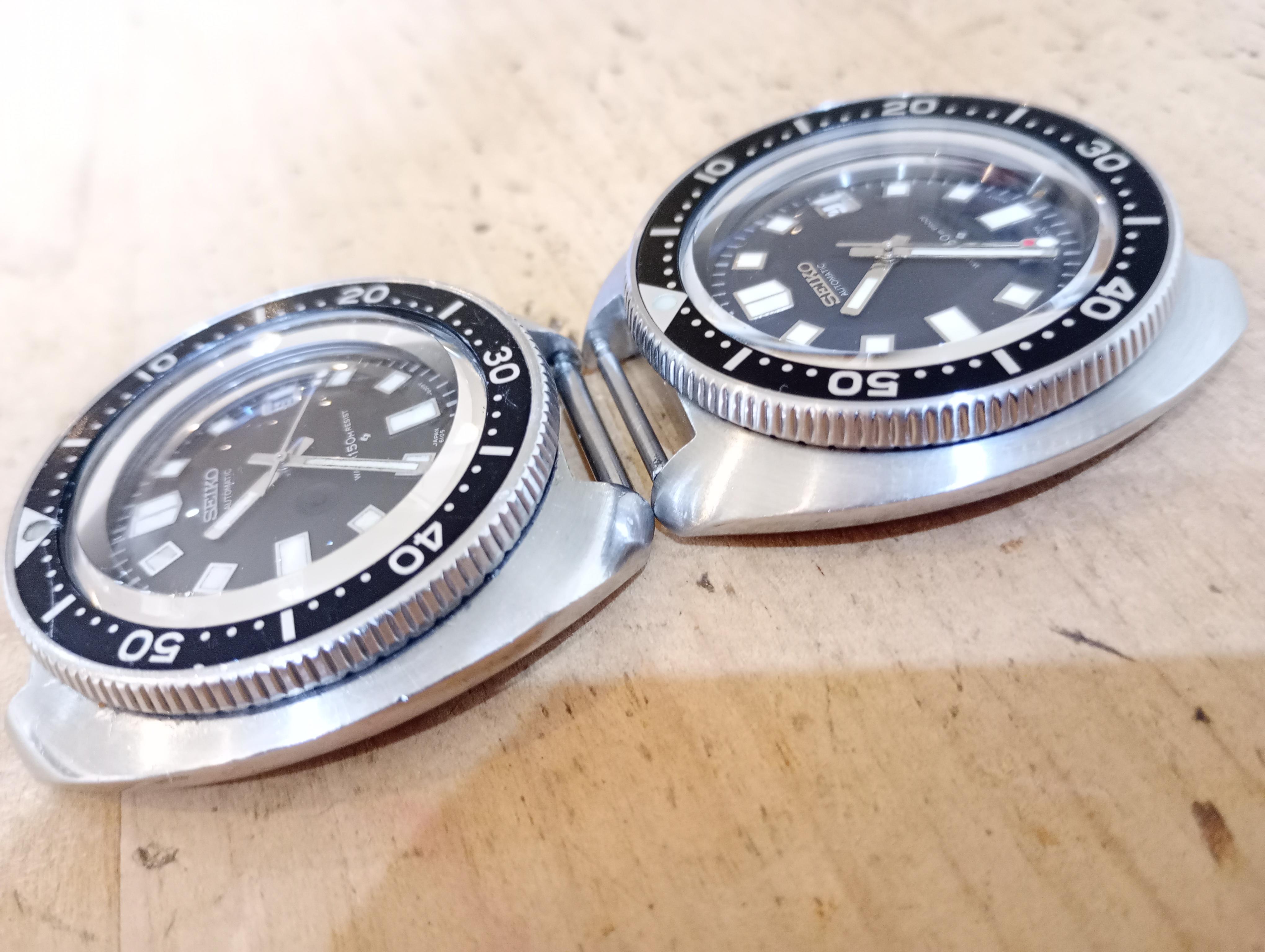
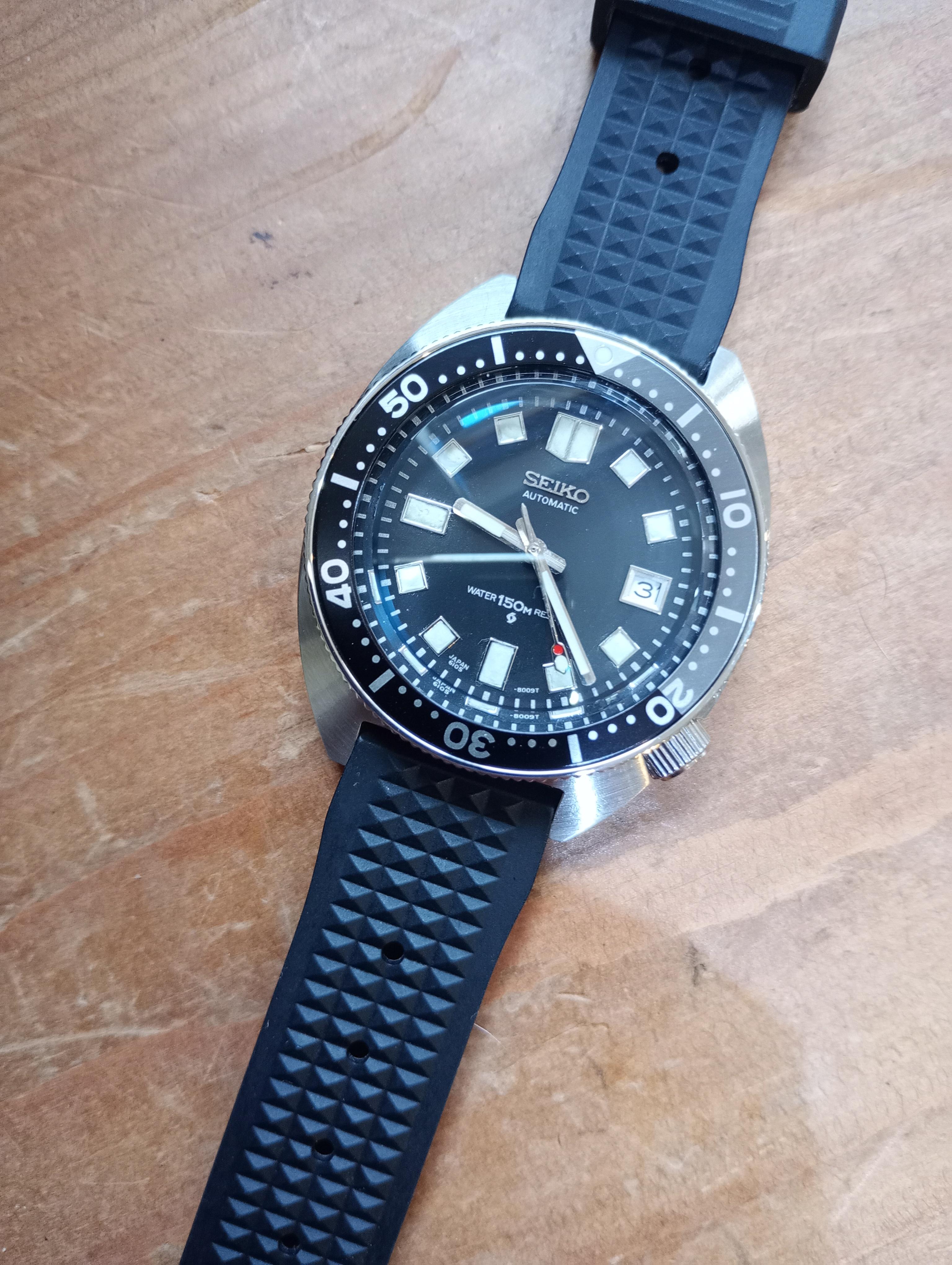
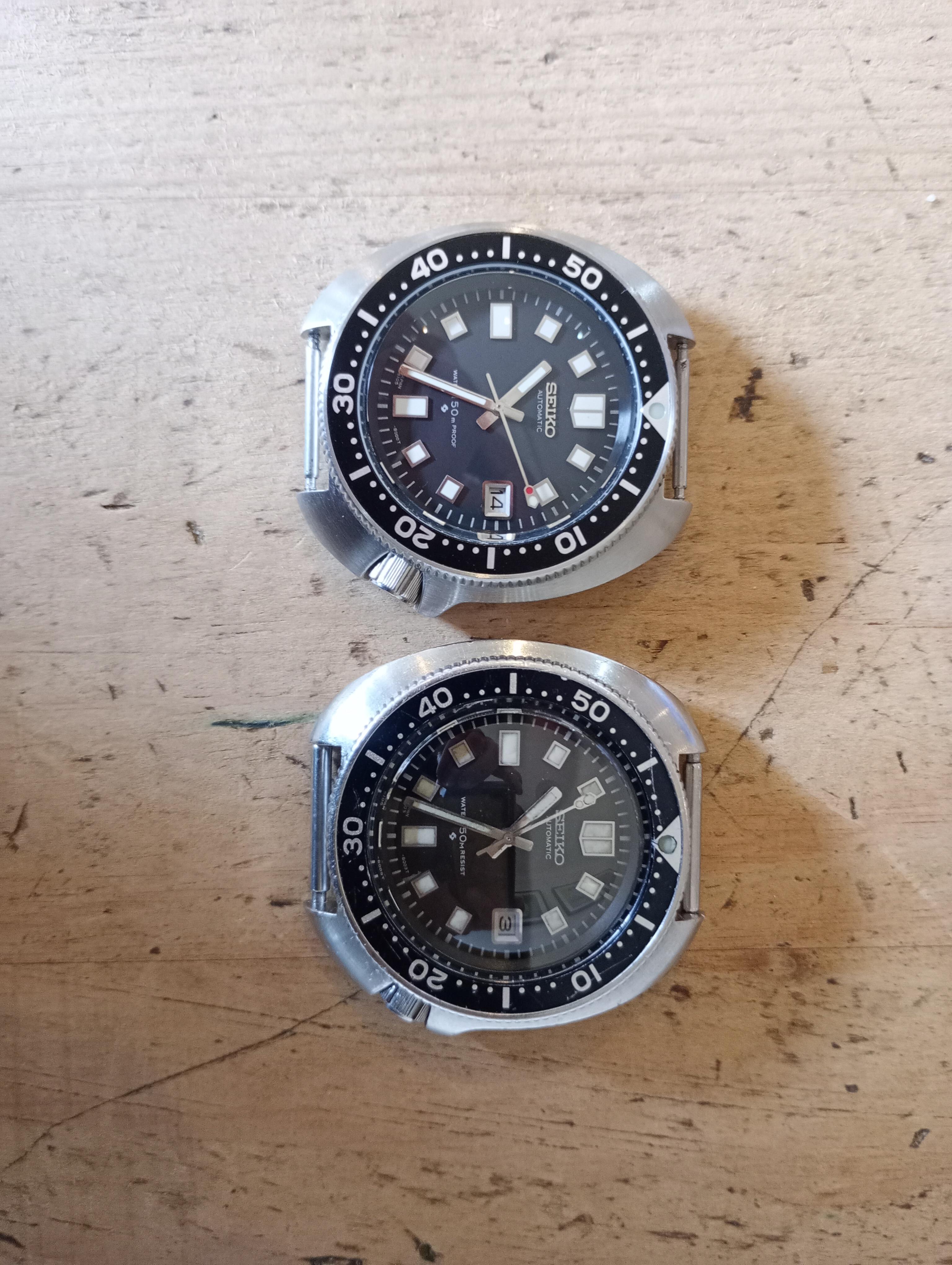
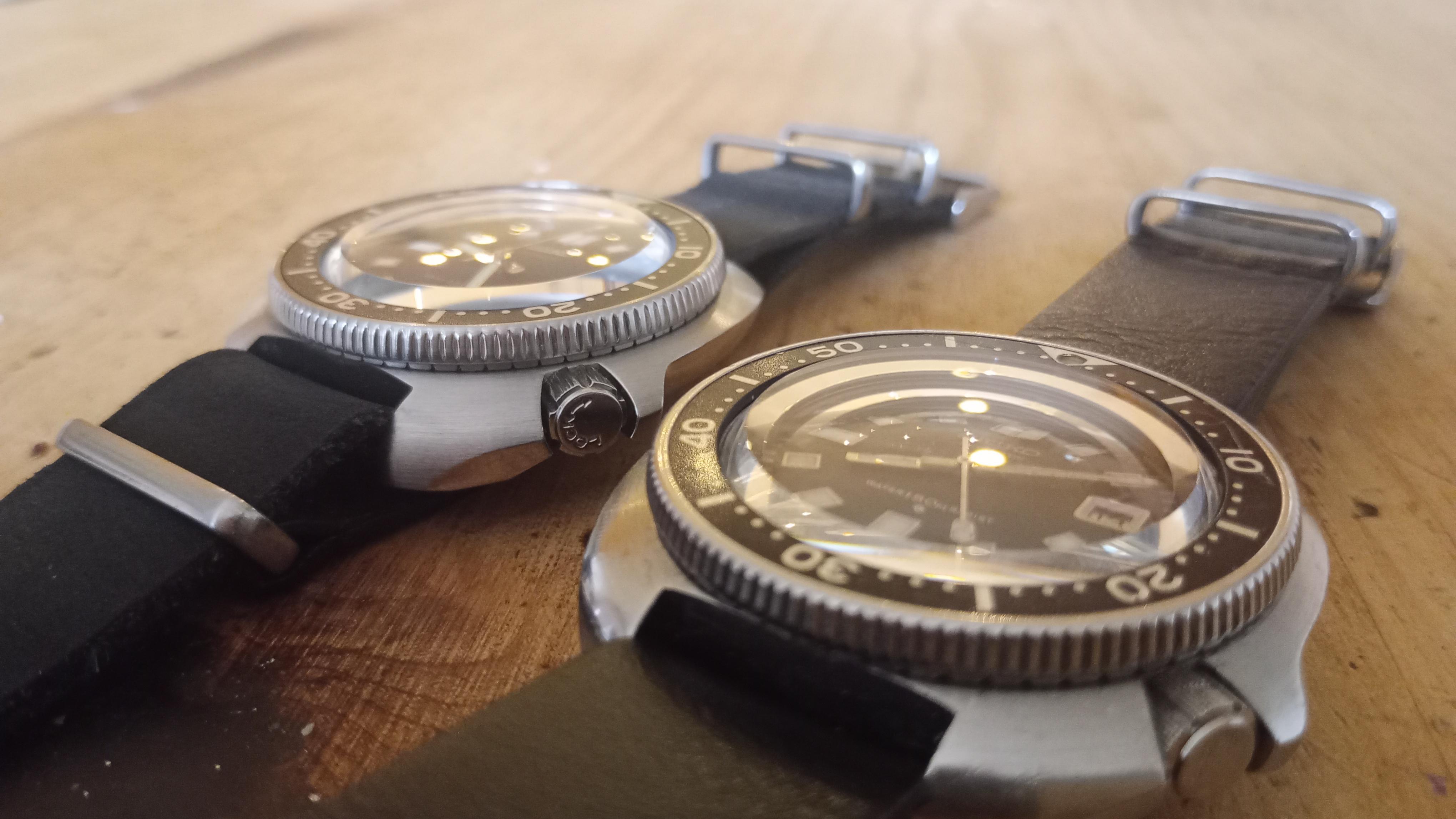
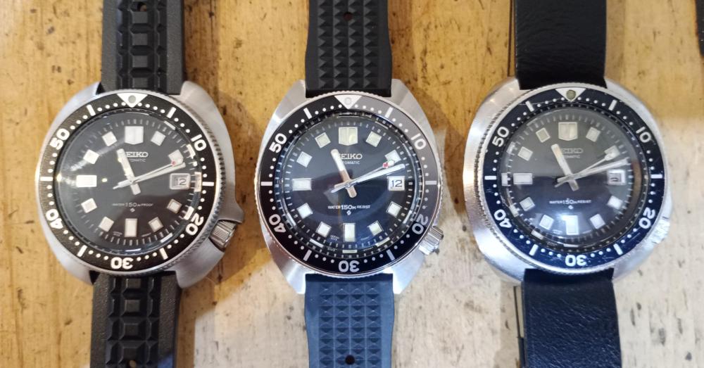
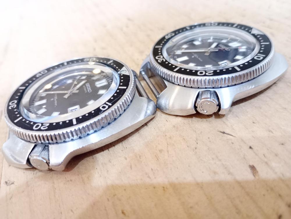
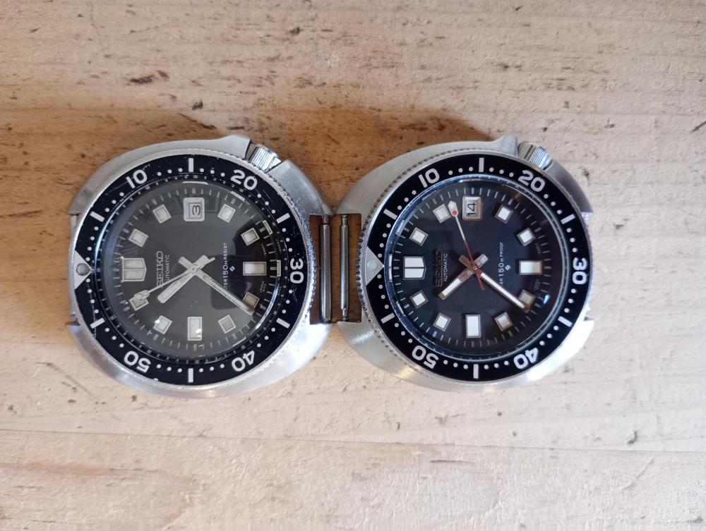
Finally completed what's been a bit of a long term aim for me - a 1:1 homage of the 6105-8009... I say 1:1, there are a couple of very small differences along with the different crystal type - bonus points if you can spot them. A slim case from Ali also arrived - bought to see how I like it, and have dropped in the movement and dial from a previous build. I may go a bit further down that rabbit hole eventually, depending on how I like it... so far it feels like there's something missing, having become used to the later version. I'm not altogether pleased with the black/grey bezel insert - my black didn't fit quite right - though may stick it on a grey NATO which could look nicer... Pics alongside the real thing:


 1 point
 -
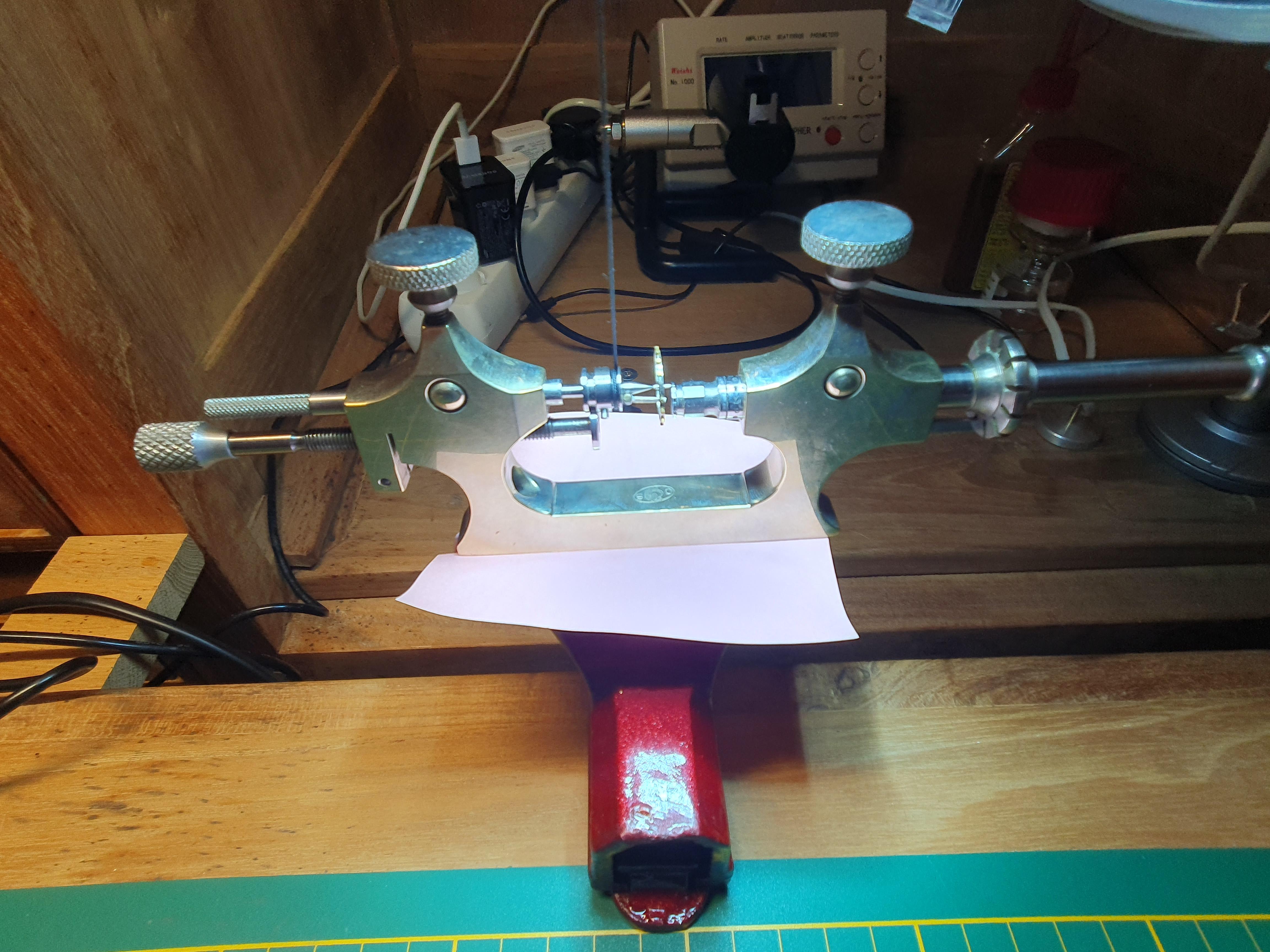
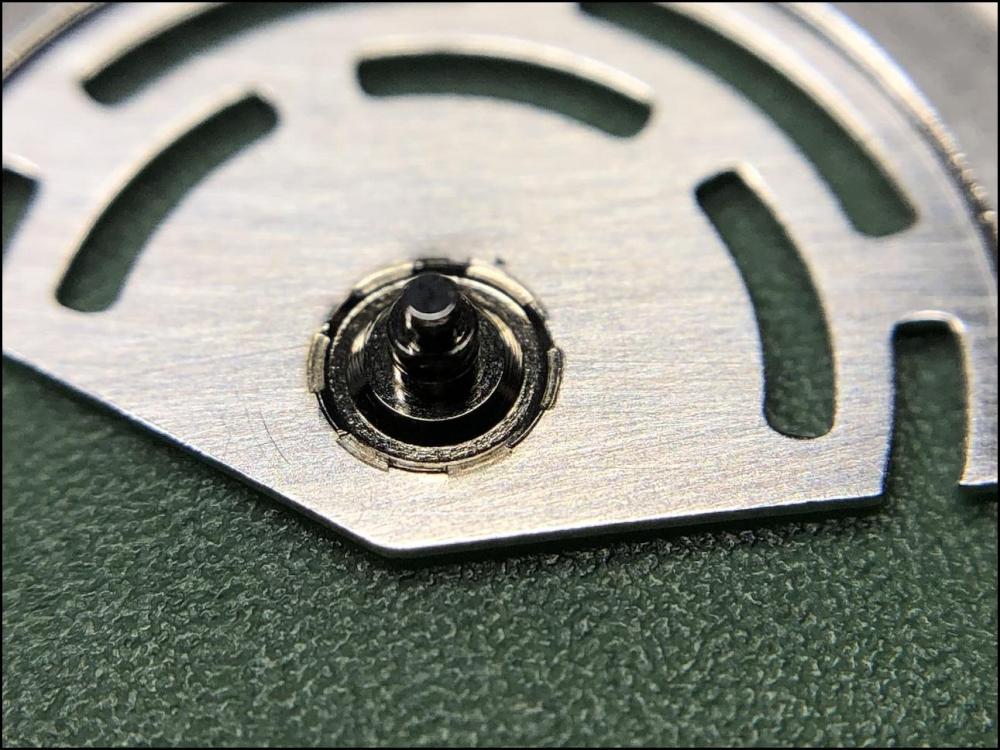
Testfitting on the plate after burnishing the pivots on the jacot lathe.
 1 point
 -
Hi Richard. Should Identify the Engine type , theres 1400CC TU3 , as well as 1600CC TU5P might have other types too. There must be virtual peugeot fan clubs you can find on the net. Mother gifted me a brand new SD V8 2020, have only driven it 5000km, don't beleive has power steering, such little car , I see no need for power steering. Risky buying reconditioned ones? Might be daig with tester machines. Rgds1 point
-
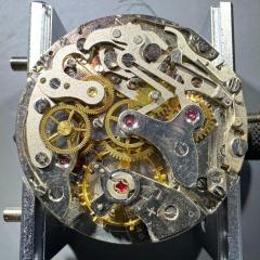
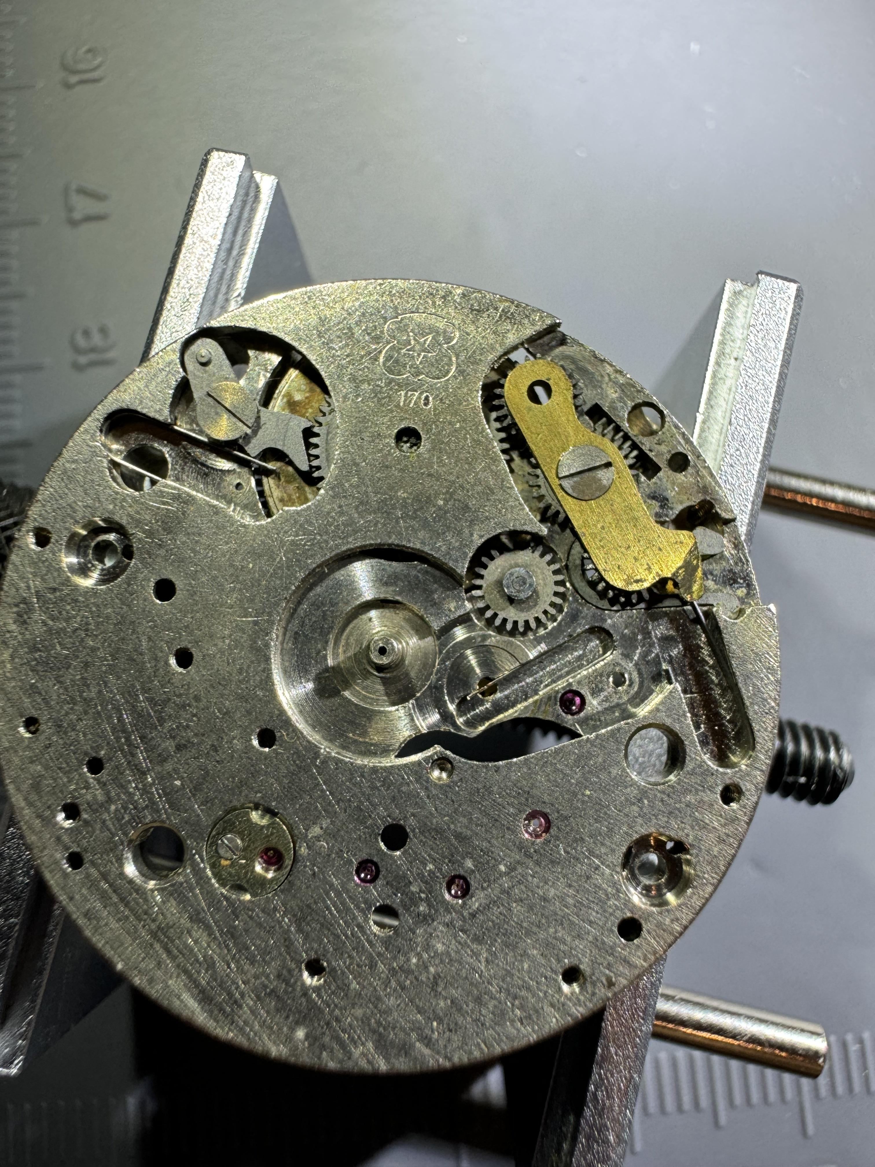
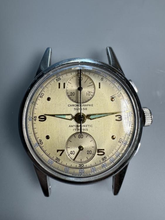
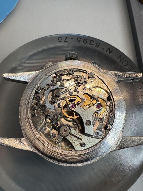
I just finished a somewhat long running restoration on a Chronographe Suisse Venus 170, and as a new forum member I wanted to share some thoughts on the movement based on my experiences with it in the hopes it might be helpful or perhaps spark an interesting discussion. First off, the Venus 170 seems to be well regarded, and it does have some nice features, including the column wheel mechanism, the use of an oscillating pinion to for chronograph engagement, and the fact that the top/bottom orientation of the subdials allows the stop/start button to be placed immediately adjacent to the column wheel, which in turn makes for very smooth and low-effort actuation of the chronograph functions. All that said, the Venus 170 has some... interesting design choices that make this movement, in my admittedly limited experience, a somewhat cantankerous beast, even compared to later chronograph movements (for the record, I have also restored several subsequent common chronograph movements at this point including the Venus 188 and 200, Landeron 48 and 149, and a Valjoux 236). Here are some of the things I didn't like, as a watchmaker, about this movement: First off, the chronograph operation depends on several rather small and delicate springs. Only two are of the more robust "engineered" type - the column wheel jumper and the hammer spring. The others are cheap "bent wire" springs that tend to get a little tired with age, which can lead to unreliable operation. Most of the chronographs I have worked on have a very simple & classic train-of-wheels layout. Not so the 170, which has a offset 2nd wheel and canon pinion, which is significantly more difficult to remove than a convention center canon pinion. It also has an unusual keyless & motion works design to go with it (pictured above). The use of rocker bar mechanism for the keyless works, as opposed to the more typical (at least in swiss movements) sliding clutch makes sense, as it allows the winding wheel and click to be placed on the dial side, away from the chronograph parts. A bit more baffling (at least to me) is the design of the motion works, which uses a wigwag mechanism for the minute wheel with a spring tensioner, which you can see in the photo with the minute wheel removed. I'm generally pretty good at puzzling out the rationale behind even odd or unusual design choices in watch movements at this point, but I have not been able to deduce why this wigwag design was necessary, and it was the source of multiple headaches when I was trying to get the watch working properly. In particular, the wigwag-ing minute wheel tends to disengage from the hour wheel if there is even a small amount of friction affecting the minute pinion or hour wheel, particularly when the setting mode is engaged and the watch is adjusted in the retrograde (counter clockwise) direction. This combined with the fact that the minute pinion (which fits around a fixed post in the center of the movement as the canon pinion is offset) and the hour wheel are closely coupled and fit together very snugly means that it is very easy to provoke this mechanism such that the minute and hour hand actually start moving together, which completely throws off the hand alignment in a way that can only be fixed by taking the hands off (at least this particular Chronograph Suisse model has a removable bezel so you can do this without uncasing the movement, but removing and re-installing the chronograph second hand is a huge PITA since it has to be aligned so carefully!). I wrestled with this problem quite a bit, ultimately resorting to polishing the interior and bottom of the hour wheel to minimize friction with the minute pinion and applying more lubrication to these parts than I normally would, before I got the watch in a state where I could set the time reliably. By the way, I had to steal some parts from a donor movement in order to get this watch running, and another thing I noticed is that there were some surprisingly significant design differences between the two movements, even though they were both Venus 170. This meant that, while most of the parts were interchangeable, some were not. A good thing to keep in mind if you're working on one of these. In any event, I know the 170 is much-loved, but in general I can see why later chronograph movements by Venus and others didn't carry forward some of these unusual design decisions.
 1 point
 -
I play with cars more than I play with watches. There is not enough information there to be able to help much. Think of the car like a watch that's having problems, and give us more information. What is it doing that it's not supposed to? What did the internet tell you the problem is? What is your skill level with automotive maintenance? One banana for me might be ten for you.1 point
-
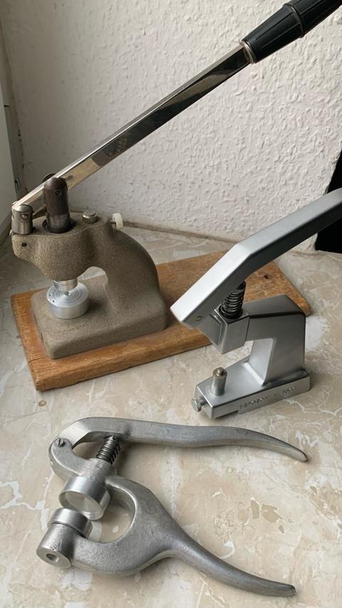
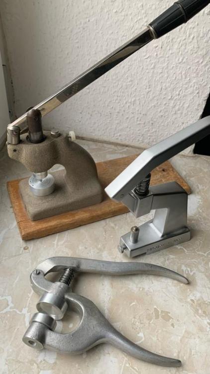
Preferred the big one and the pliers type:
 1 point
 -
Looks damn good to me! I knew you would ace it1 point
-
Bottom hole 15mm top hole 15.5mm. Which is strange because the dies fit in the upper and lower holes. See attached my set.
 1 point
 -
It's a touchy system. I use 9020 on the little satellites, and on the arbor that carries them where the other wheel sits. Hp-1000 closer to the rotor and for the rotor. Sometimes they still seem "sticky"- especially when hand winding. Then I reclean thoroughly and go with 9020 everywhere. I've suspected the plastic internal gear in the barrel bridge but never pinned one down as faulty. But some work just as smooth as silk, so they are capable of that. Not my favorite auto system.1 point
-
In that movement, Part #33 (Driving wheel with cannon pinion) does sit under the minute train bridge so it is captive when the movement is assembled. But as mentioned above, part #37 (Hour wheel) is placed on top of the driving wheel and is kept in position in a watch only by the dial and dial washer, so it isn't affixed to a bare movement and is shipped as a loose part (or, unfortunately, sometimes not provided at all which gives people another part to chase down after they get their new movement)! During assembly, you should be able to drop it on the new movement so it fits over the driving wheel and exposed second wheel pinion and under the dial.1 point
-
My respect, the staff looks professional. If the material is good and the hardness is correct, then You have made perfect balance staff. Of course, reducing the pivots diam on the Jakot toll is something that needs to be done, and this is another job that is tricky for one who will do it for first time. Nothing frightful when some experience is gained, but usually a newbie will break some pivots in the beginning and this is normal thing. Will say here that I personally prefer not to use Jakot tool, but do the burnishing on the lathe right after the pivot has been turned. This method is not safer, and some experience is needed too.1 point
-
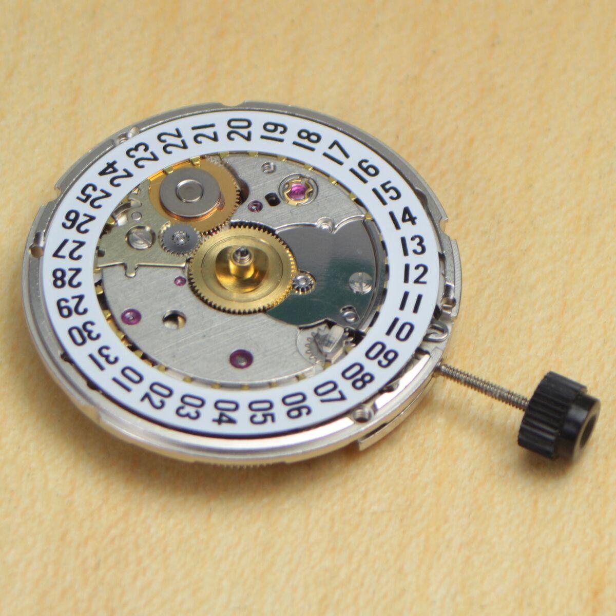
Are you sure they do not mean the dial side centre wheel, that the hour hand fits to? That and the dial washer are often removable with an uncased movement, so could be supplied packaged separately to prevent loss. eg. The brass wheel and spring washer in the centre of the movement, as in this photo?
 1 point
 -
Seriously, we sometimes have a watchmaker make a staff as part of their bench test. Most, who were recent multi-year watch school grads, failed. These are folks who spent months doing supervised turning. What you've done is super impressive.1 point
-
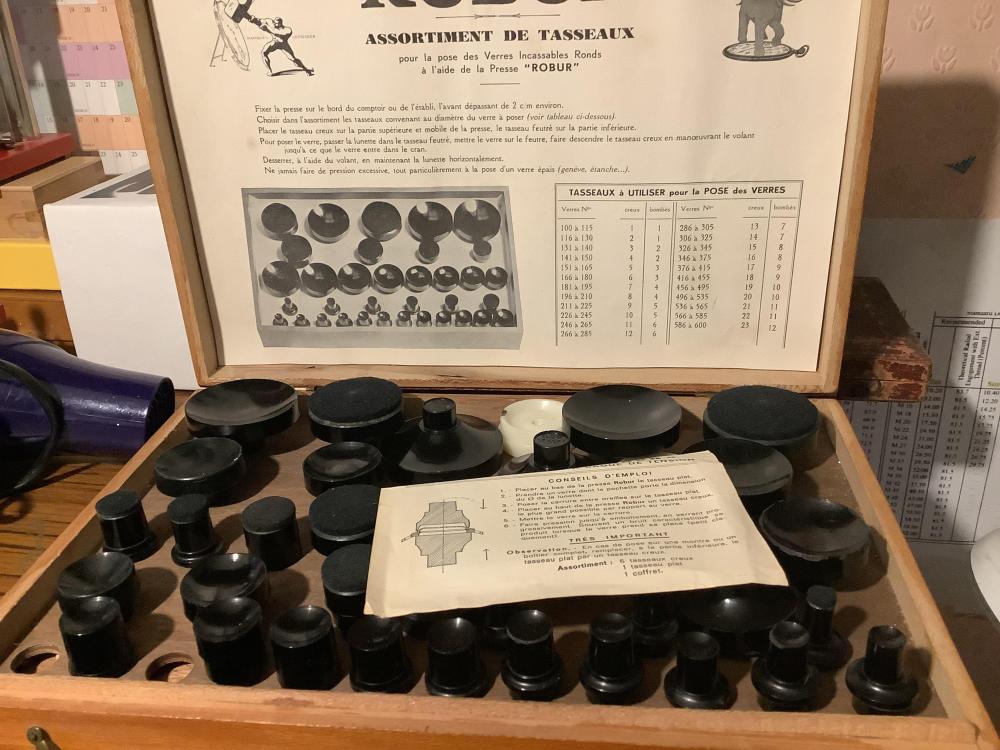
No, I don't. I've set up the "complete set" to have lots of extra's. So, it is only sold as a full set. Still an affordable price!1 point
-
R, you're exactly right about that! I practised pulling the spring back (right hand) and holding it (left hand) while also controlling the movement holder (left hand) about 5 to 10 times before I felt confident to do the job. Practice makes perfect, and sometimes practice is a must not to make a mess. Lovely movement holders! Thanks for sharing the pictures!1 point
-
So, my watch repair friends, the agony is over. The new axle has been riveted! As I lifted the brass hammer to whack the punch, @Jon's words suddenly came to mind: "I'm sure you will ace it. What you believe, you become!" I haven't yet had a chance to test it, but as far as I can tell it looks good. Thanks for the practical advice, explanations, videos, articles, and encouragement. Invaluable! Feeling pretty good about myself tonight!
 1 point
 -
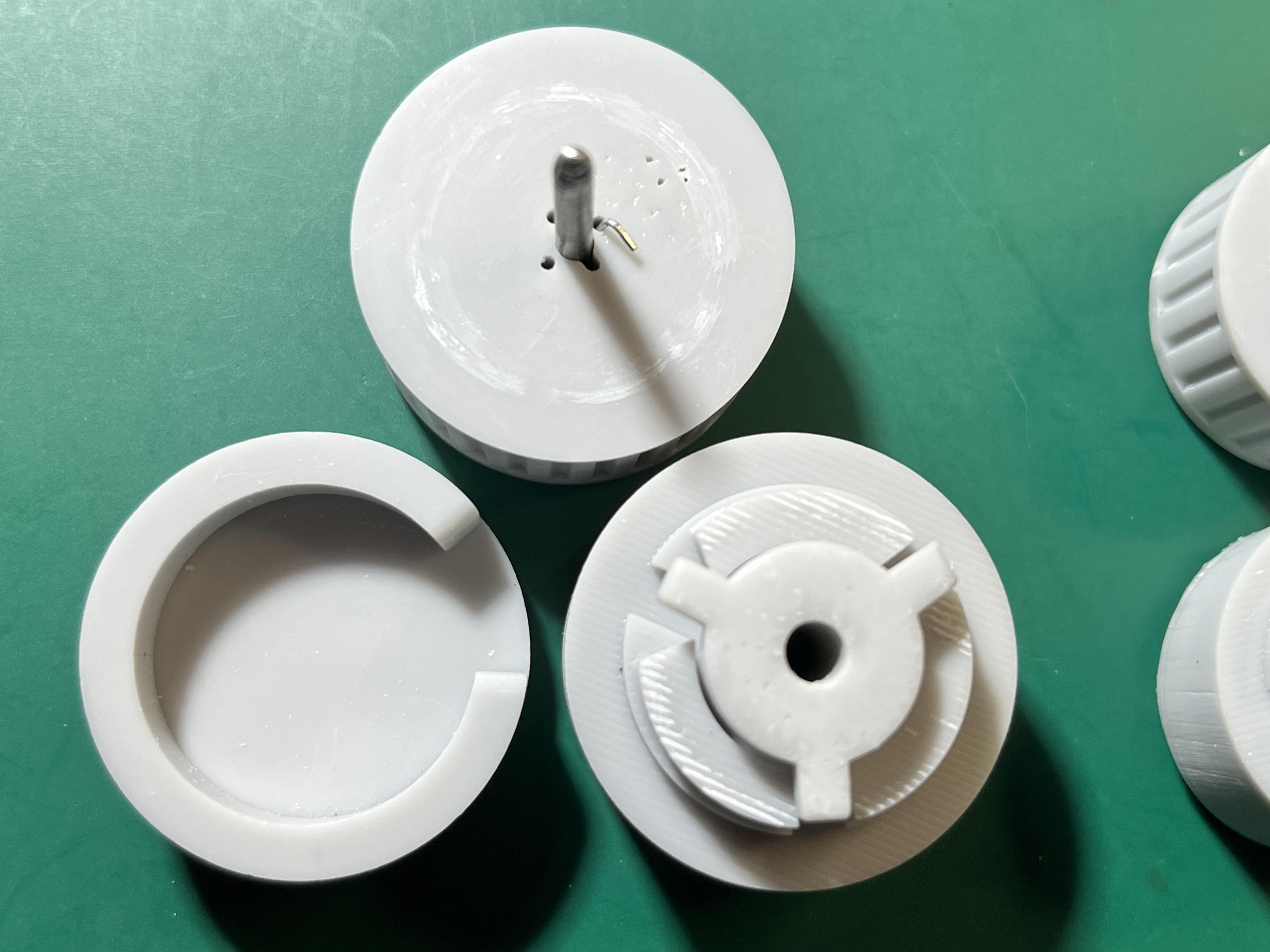
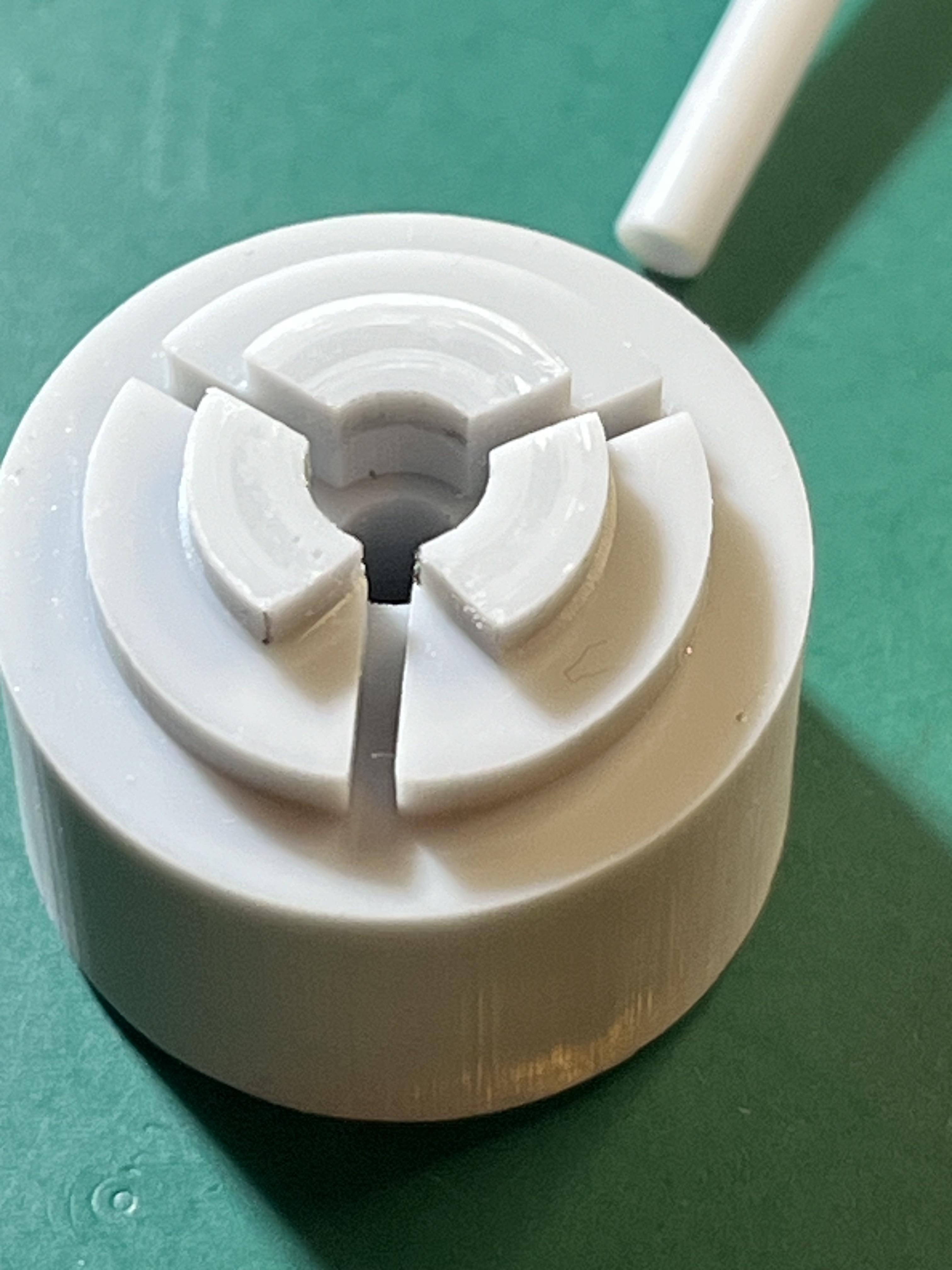
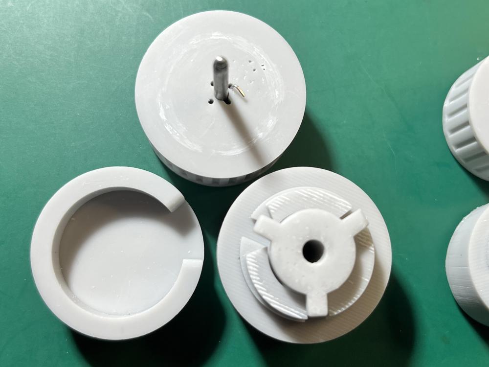
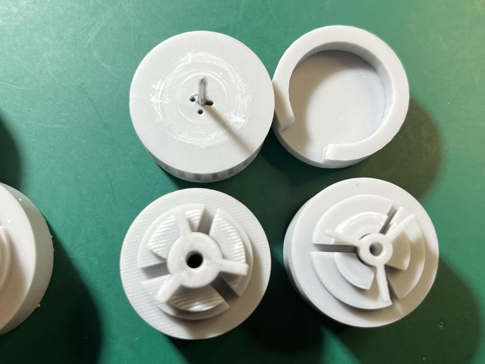
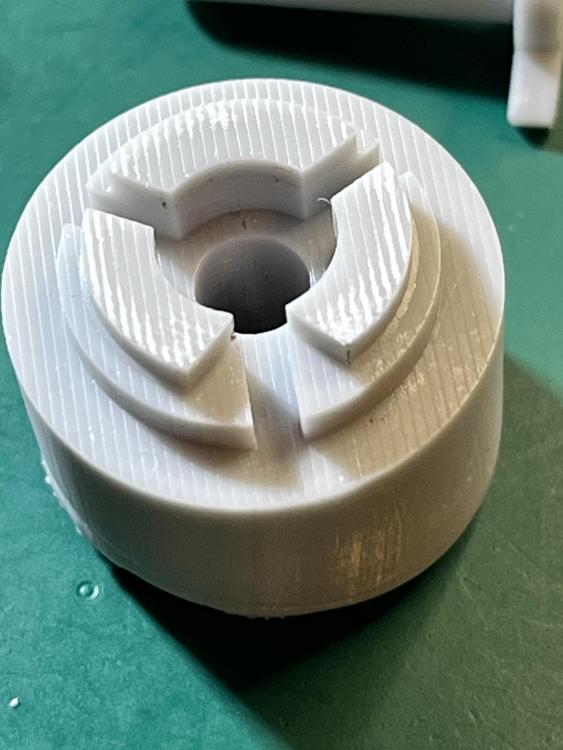
To date I've made three: 14.0, 9.0 and a custom 5.5mm. I initially printed directly onto the build plate, but I had difficulty getting the larger winders off the plate and broke some so I've ended up angling them by 5 degrees and printing with supports (which is why the two larger winders look stripey ... 50 micron layers at 5 degrees gives roughly half millimeter stripes). I printed the 5.5 first and used it once for practice on the broken spring before using it on the replacement, and I've used the 14.0 just once, I think. I printed the 9.0 yesterday and used it twice today (for the same spring ... I didn't notice that the tail was sitting in one of the slots and didn't position it properly in the barrel before pushing it out of the winder ... sproing -- glad I was wearing eye protection!). The spring scrapes the resin a little and I clean the spring before and after pushing it into the barrel (so I get both sides) with some Rodico. There is a little 'polishing' where resin rubs against resin but otherwise the winders look almost untouched and look like they could easily do dozens of springs. These were printed using Monocure Tensile (https://monocure3d.com.au/product/tensile-industrial-strength-resin/) but the pieces are so 'chunky' that I don't think the brittleness of regular modelling resin is likely to be a problem.
 1 point
 -
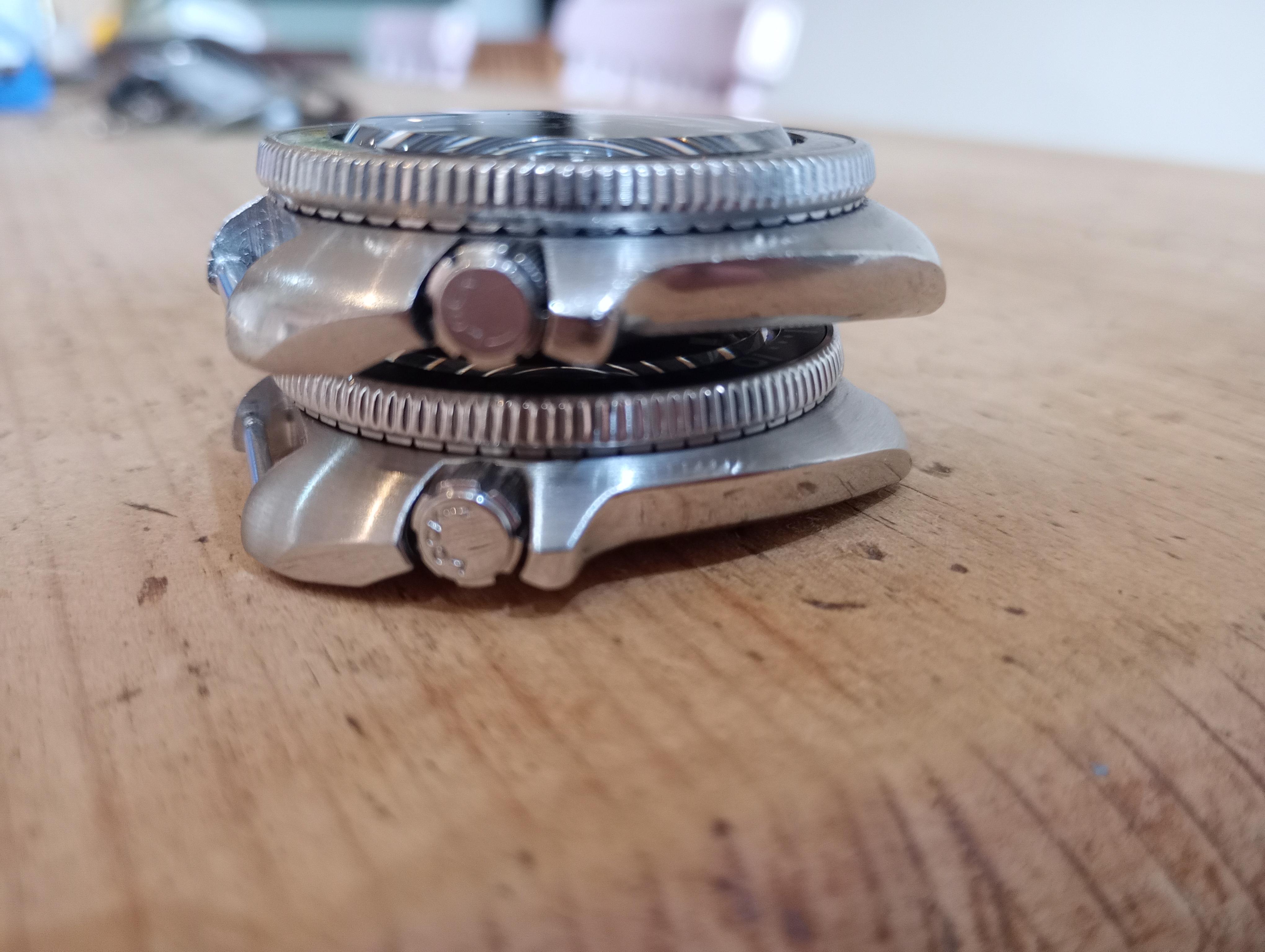
Switched out the crystal in the 8010 wannabe - not perfect as I'd much prefer a double dome but height is far more appealing...
 1 point
 -
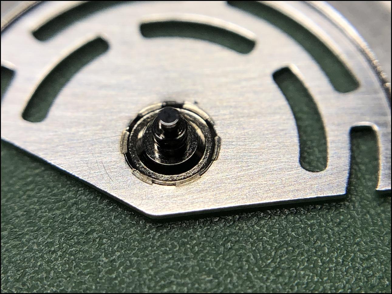
OK, now I understand that the date wheel is actually in the center and the date is pointed by dedicated hand. Am I right? Then yes, the driving wheel is one for both date and day. Then, look why the position of date changing finger in this wheel is wrong. Obviously the day finger is placed as in the manual. But the date finger is not visible on the picts. When the day finger points right against the day star, the date finger must point against the date star. May be the date finger is not rigid, but loaded with spring and it has been for some reason blocked in wrong position and the spring can't return it to the correct position1 point
-
Have you followed the previous instruction for the rest of the movement? Edit Just had another think about this and if they're set as the diagram then one should drive the other so can't understand why the difference in time.1 point
-
I have found that the potential pitfall in relying on a timegrapher, is that it doesn't necessarily equate to wrist time. Most of my watches are vintage or modern NH series Seiko, the variation in seconds per day in various positions can be , lets say 30 seconds worse case scenario. Trying to regulate to various positions is a PITA. I prefer to wear the watch for 2 days, using wrist time error see how far out it is, then regulate it on the timegrapher. This will vary from person to person depending on their daily activity. I did put an Omega on the timegrapher and it remained within 2 seconds in all positions.1 point
-
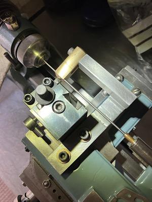
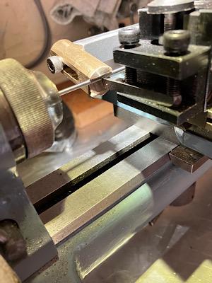
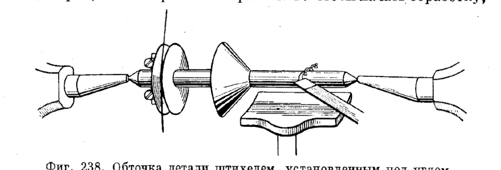
Something important about the cutting itself. No mater what kind of cutter - the steel ones can easy get dull, carbide ones can chip easy. One have to be carefull not to break the tip in both cases... On the picture is shown the correct position of the cutter when cutting most of the work. Pay attention where the shavings come out from. They get out from the middle of the cutting edge of the cutter, the tip is not engaged in the routine cutting at all. The tip is only used to form sharp internal angles. This way of holding the cutter gives longest time between sharpenings and eases cutting. Try to understand and use it and wili be pleased by the result.
 1 point
 -
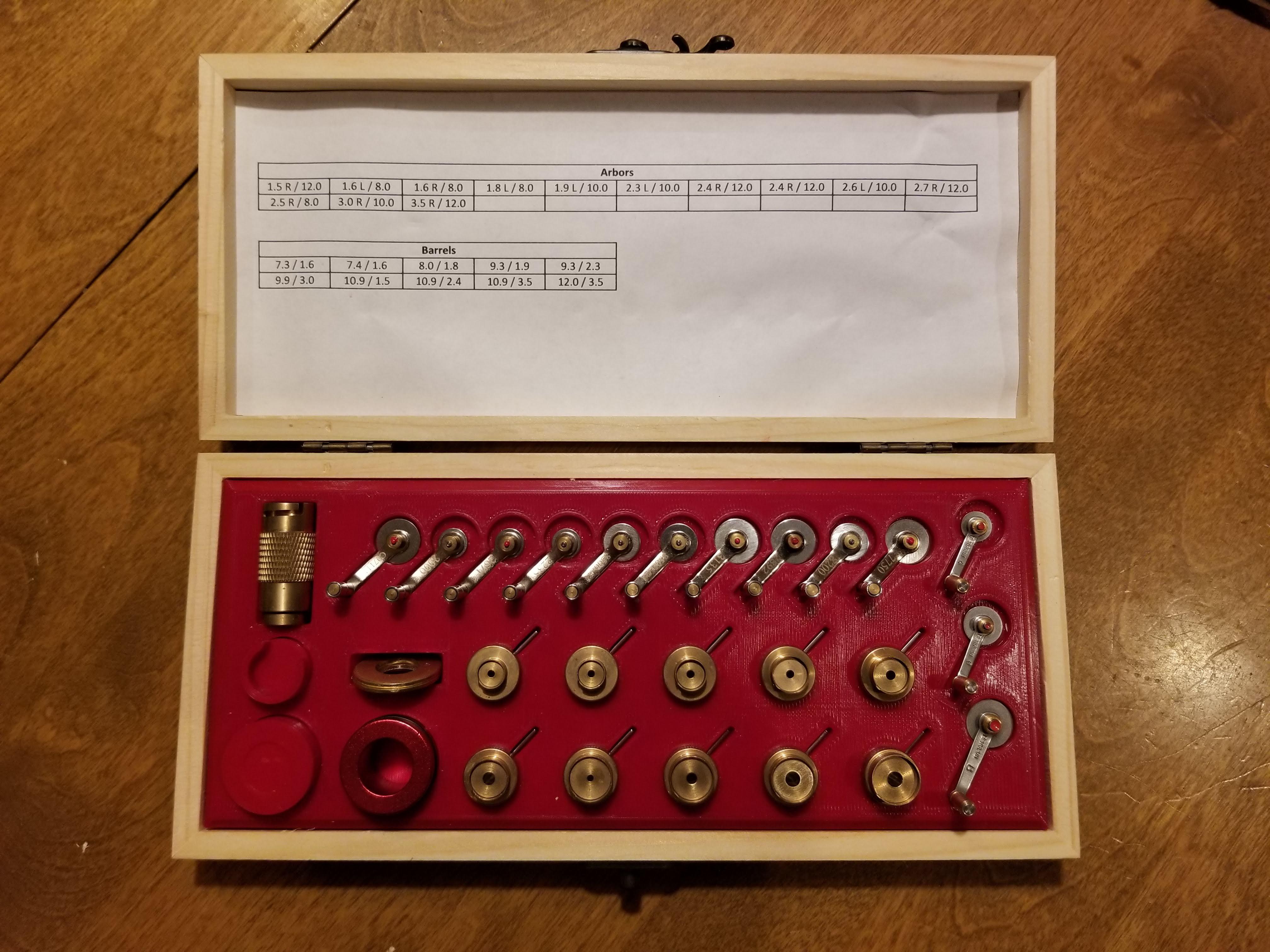
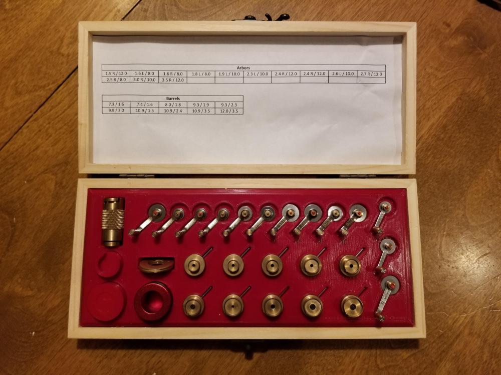
You can convert them to be more universal. I drilled out the arbor hole in some of the winders to accept larger arbors, using the generic Bergeon sizes as a guide. I did add the Bergeon #6 and #8 arbors (you can buy these separate from the winders) to give me 3.0 mm and 3.5 mm arbors respectively, as the largest in the Chinese set was 2.7 mm. That gives me more flexibility in which arbors I can use with which winders. Mainspring-Winder-Size-Charts.pdf
 1 point
 -
The numbers in the white bar are the average values over the last x seconds. You can set x in the menus. The row of +4s are the s/d of the last four measurement periods. This short history is useful if the traces are wavy. Yours are just too good (dead straight)! The angle of the traces (very slightly up to the right, i.e. rising with time) is a graphical representation of the +4s/d. The vertical separation of the two traces is a graphical representation of the beat error. In your case it's 0.0ms, so the two traces appear to be one.1 point
-
Cuare’s reply covers the Chinese winder set and their capabilities very well. An alternative to getting calibre specific sets like these is to slowly build a set of quality Swiss winders. They are sold individually, so you could buy a Bergeon handle and the 2 correct diameter and wind direction winders you need now initially, and buy the other sizes as you need them over time. If you come across a movement you lack a winder for and feel you won’t likely use that size winder often, then just buy a replacement mainspring, because they come already wound and ready to be pressed into the barrel You can usually sidestep the need for having both left and right winders in each size by reversing the wind of the spring as follows - wind the spring into a slightly undersized winder, push it out into the correct size winder to suit your mainspring barrel (thereby reversing its direction), and finally press it out into the mainspring barrel. Best Regards, Mark1 point
-
Would the below list of lubricants be suitable for the Rolex cal.3135 (clone) movement? For the grease (cannon pinion, keyless) would you prefer to use 9501 or 9504 the moebius chart recommends either. Sent from my iPhone using Tapatalk1 point
-
Excellent achievement, Endeavor. I've never heard of anyone else who has started with no prior experience with such a fine watch, and achieved such an outstanding result. Bravo!1 point
-
One more thing I like to add, as "Another lesson learned"; The Microstella tool I received from CousinsUK wasn't of the highest quality. The pointer is a bit "sticky" and there is some play between the screw and the wrench. For bigger adjustments, like the first one I did of -5s/d, this isn't such a problem, but for fine tuning it is or becomes. Because of the "play" between the screw and the wrench, that when turning the wrench slightly, you can't see, and don't know whether the screw turns with the same amount. This "error" will accumulate if more adjustments are made. So the Microstella tool from CousinsUK I received will do the job, but it's not for regular adjustment, on the same watch. My watch runs +1.5 s/d consistently, so I'm done :)1 point
-
Tools with wooden handles? Peg wood and pith wood?0 points
-
Straps made of cow hide or natural rubber would be affected.0 points


.thumb.jpg.19a9c4ff164d78d516aa9f05a063752b.jpg)