Leaderboard


Popular Content
Showing content with the highest reputation on 01/19/25 in all areas
-
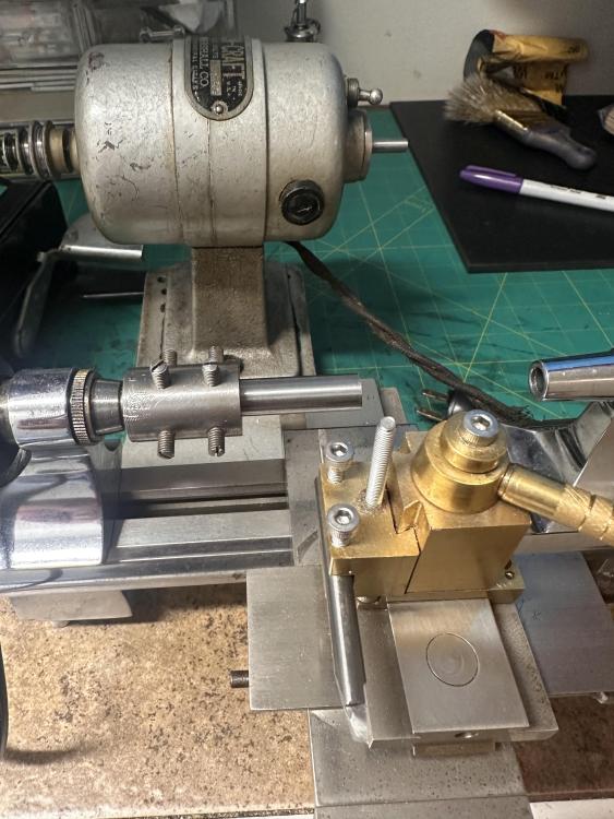
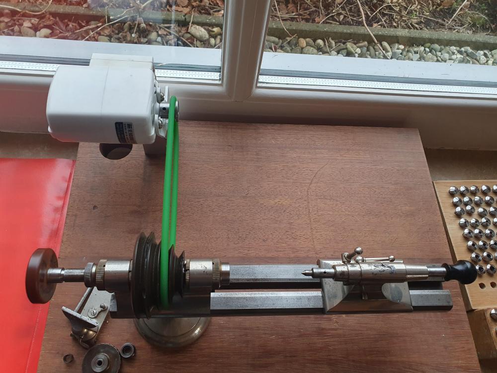
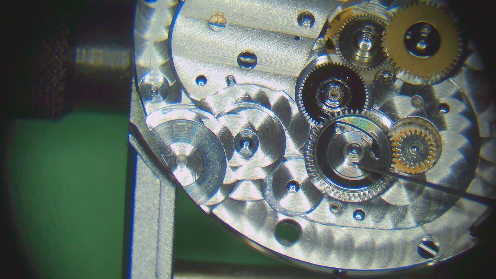
I just won an auction on a Webster Whitcomb lathe . Headstock, tailstock, tip over toolrest and a Borel base. I'll have to get a motor. And gravers. And collets (comes with a couple). And books. And. And. And. This wasn't particularly expensive, but I am expecting I'll be sinking a good chunk into completing and accessorizing it from now on... And I have all of you to thank for egging me on.5 points
-
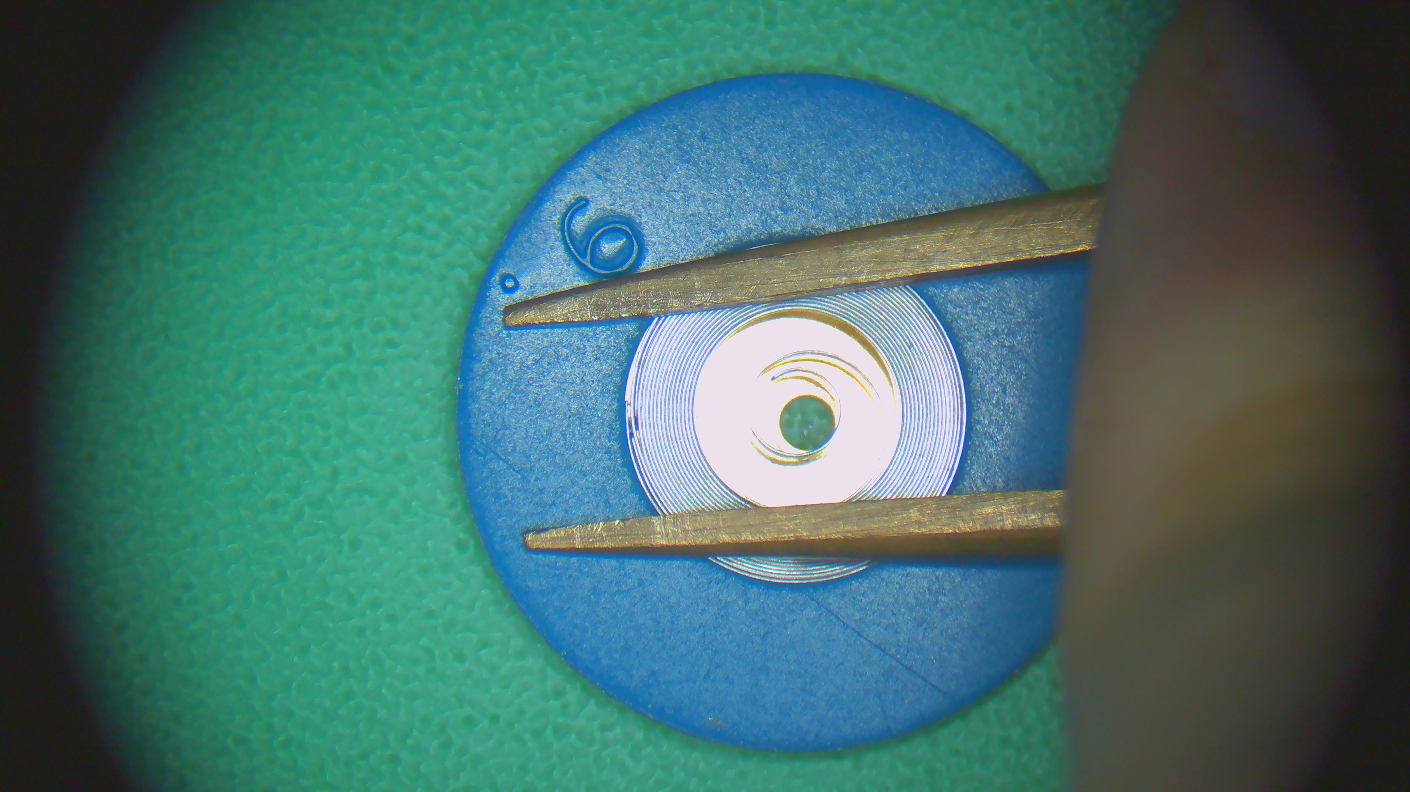
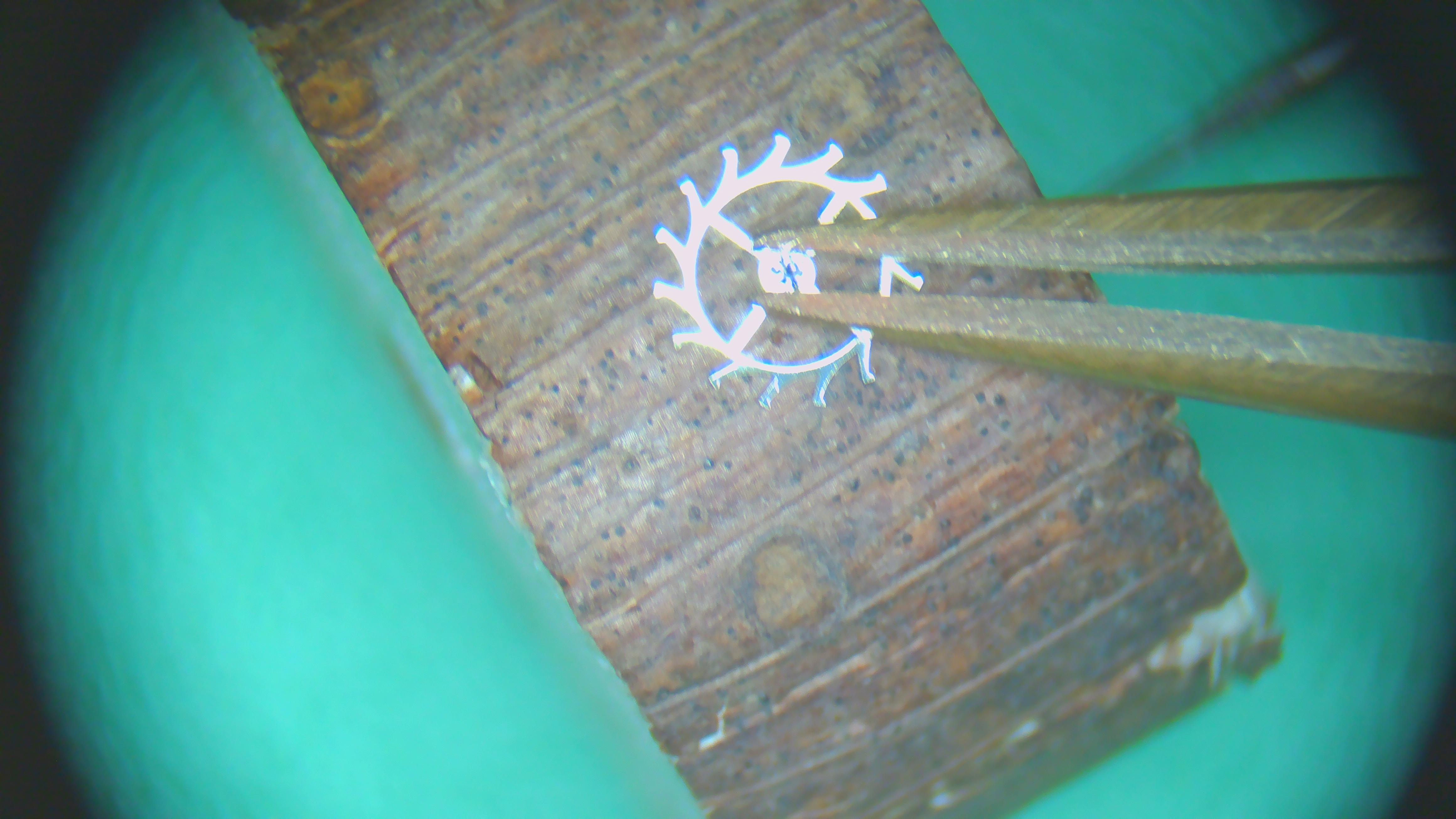
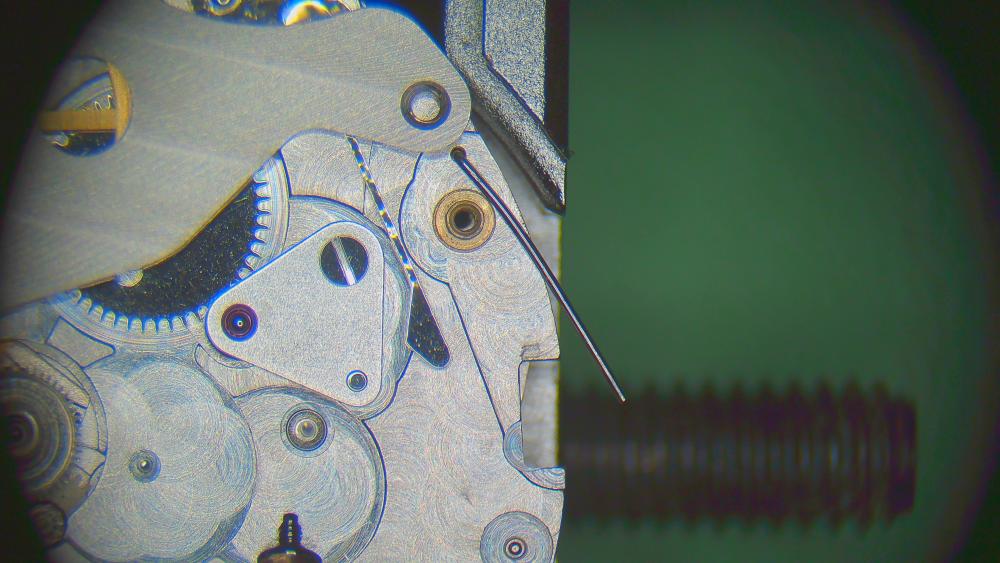
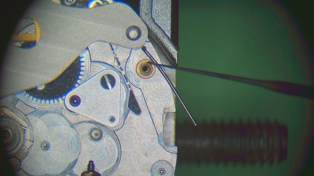
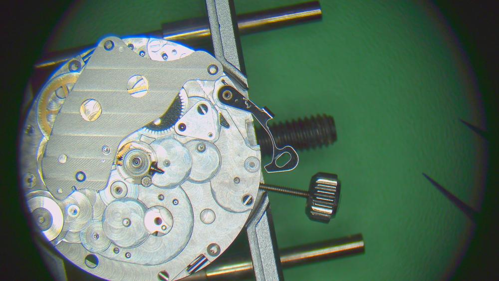
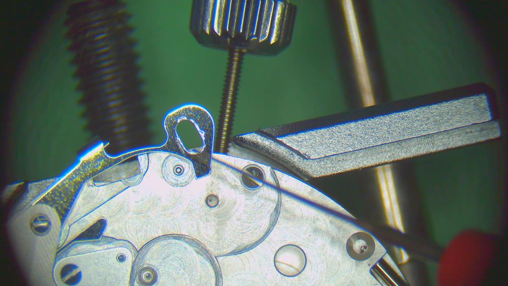
I just hold it still with a bit of brass rod - see below. The torque of 16 N.mm is the effect of a force of 16 N acting at 1 mm. Hard to visualise as we don't tend to think in Newtons. But 16 N is about 1.6 KG, or 1600g at 1mm. Still not easy to imagine. But consider it acting over a distance of about 150mm (that's about 6 inches to use oldies). Then the force to give a torque of 16N.mm is about 10g. So if you were tightening a bolt and had a 6" spanner, you would put 10g force on the end. (Not a lot, my Bergeon 4040 movement holder weighs 32g) Problem is, that doesn't really help as we are using a screwdriver BTW, one of my most useful tools is just a bit of brass rod I filed to a point at one end, and to a sharp shovel at the other - useful to prizing bridges apart, holding things in place etc without scratching.
 3 points
 -
I generally hold the ratchet wheel with a finger. Appropriately covered, of course. As for visualising 16 N.mm ... that's a torque of one Newton at a radius of 16mm ... roughly a 32mm cotton reel being turned on a pivot with enough force to winch a 100g mass. Or a 6mm diameter screwdriver handle turned with sufficient force to winch a mass of about 270g. (I am a Maths teacher.) To be slightly less mathematical, "good and tight but don't overdo it" would seem to be what is called for.3 points
-
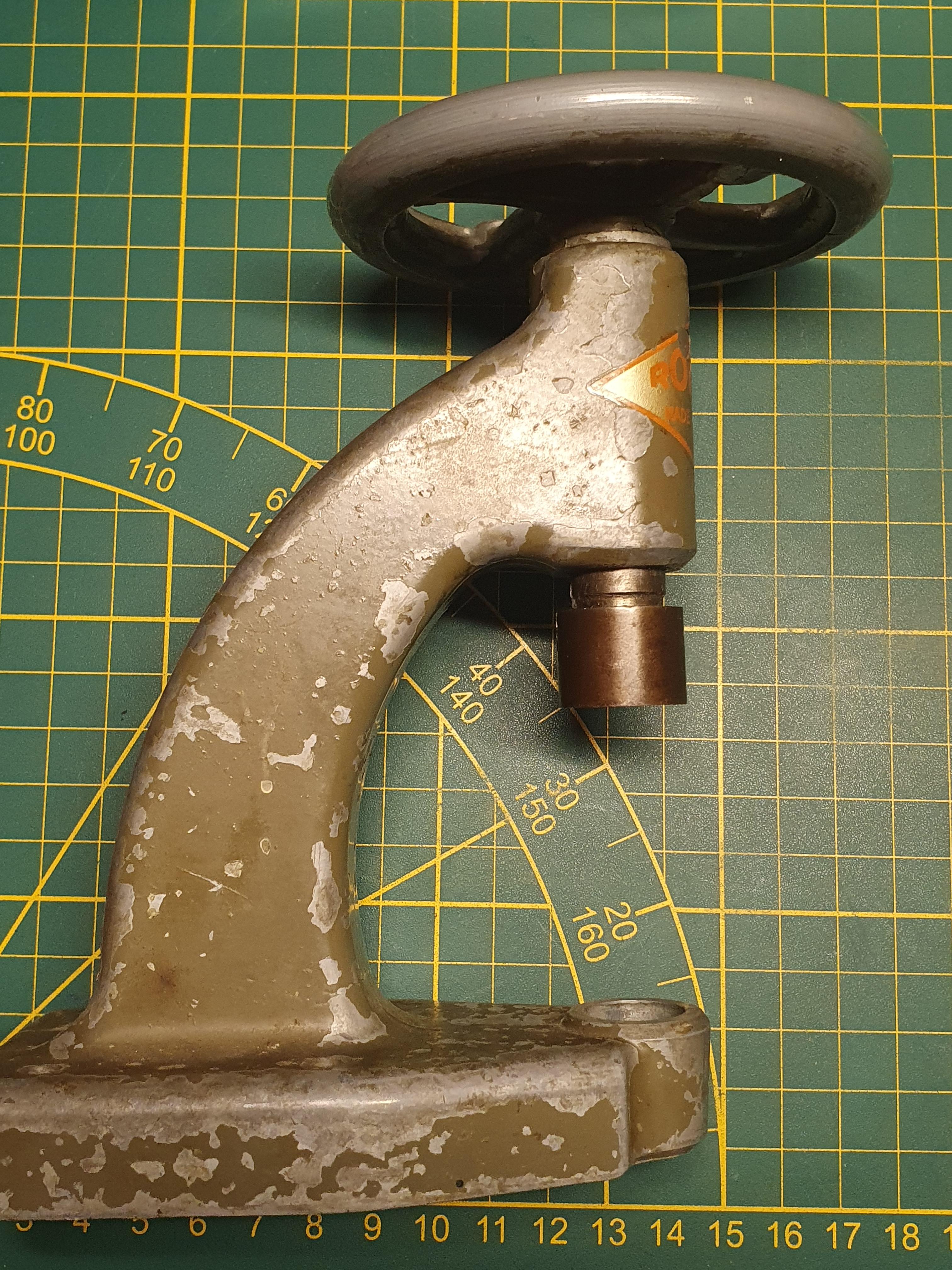
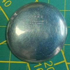
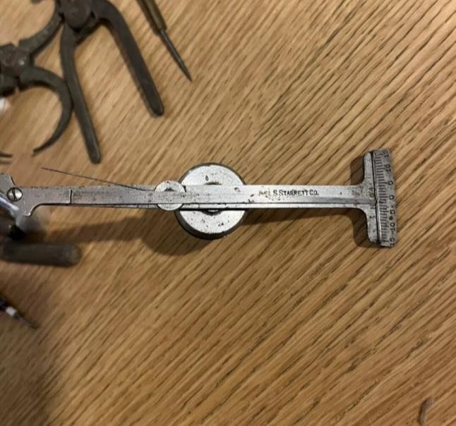
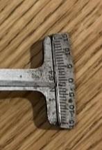
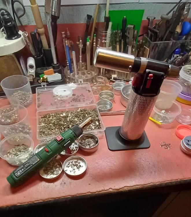
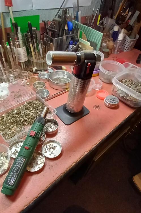
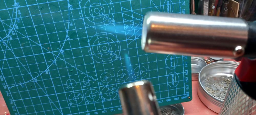
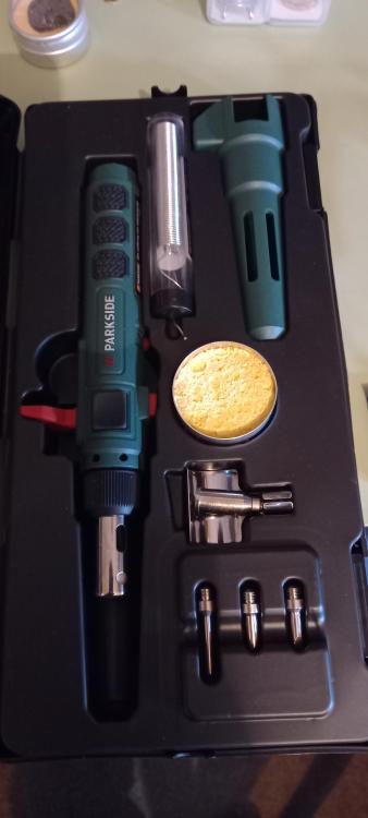
@VWatchieLook what this " Tool Junkie " just found in a watchmaker's lot, and check out the range on the scale
 2 points
 -
Well, for my XL sized fingers, 16N.mm is extremely light.2 points
-
I believe it's supposed to be the tip radius. And if possible, get rid of the borell base and mount it on a nice solid piece of wood. I believe our resident lathe encyclopedia (Nickelsilver) hates these borel stands, and who am I to disagree with him. Mass helps dampening any vibration you might get from the motor. My baby brother got me this nice piece of tropical hardwood. Weighs a ton. Absolutely solid. But a good quality cutting board should also work fine.
 2 points
 -
I thought it hadn't got any but realised from the other photo that you must have removed them for some reason?
 2 points
 -
I can't help but admire his confidence though! Speaking of healthy food, we all know a varied diet is the best. That’s why I like to alternate between McDonald's, Burger King, and Wendy's.2 points
-
I'm a bit puzzled on what the current status/issue is. Did that free up the balance? New issue? Because earlier: Please don't take this the wrong way, we're only trying to help, but It seems you're now jumping from issue to issue on an assembled movement. At this point I can only repeat my (and Neven's) earlier advice to start again from scratch (methodical, function groups, etc).2 points
-
Absolutely, and it shows with all desirable clarity that we, whose ancestors were Vikings, have enormous advantages over you Christian heathens Furthermore, I am old enough to be blessed with a Viking name (which no English speaker can pronounce) that means "son of heroes."2 points
-
@nico, I've now posted the full walk-through for this calibre here:2 points
-
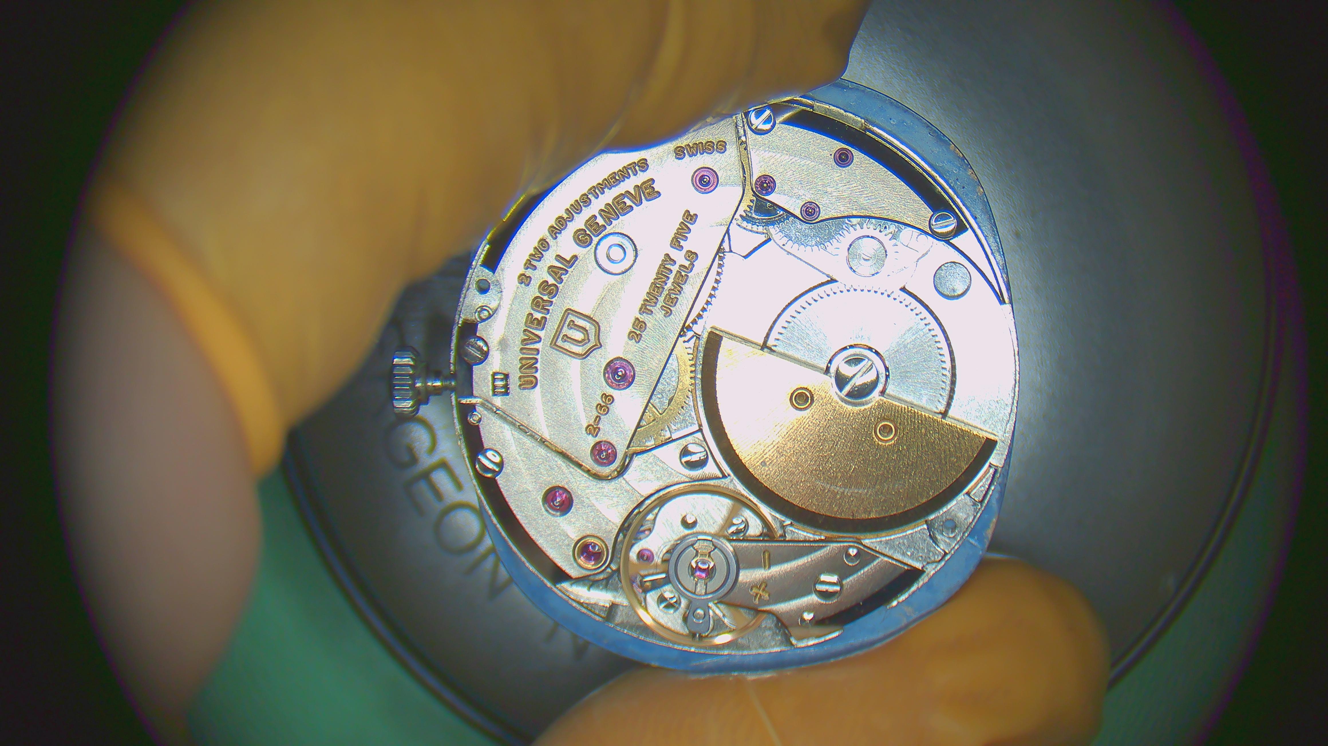
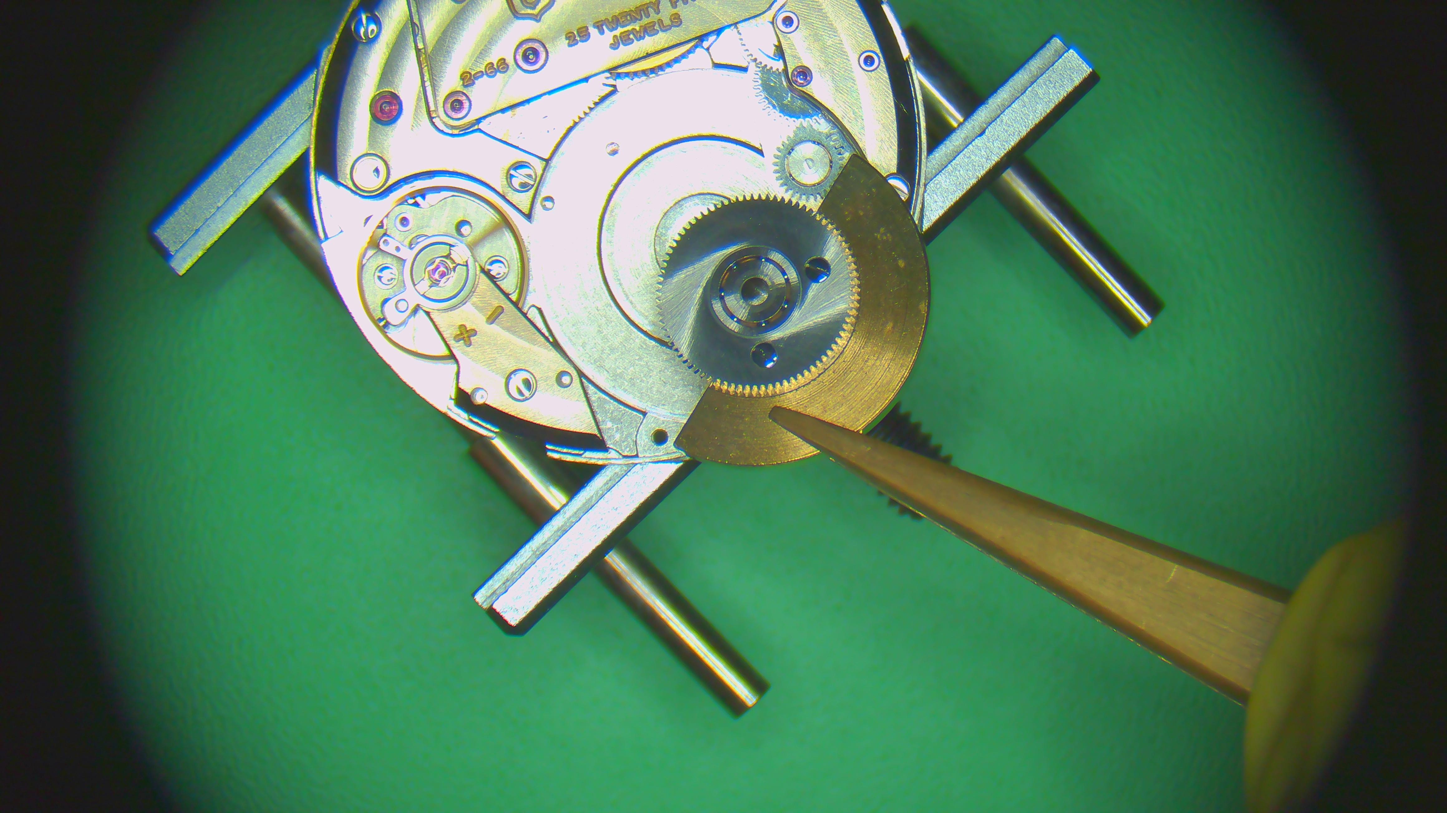
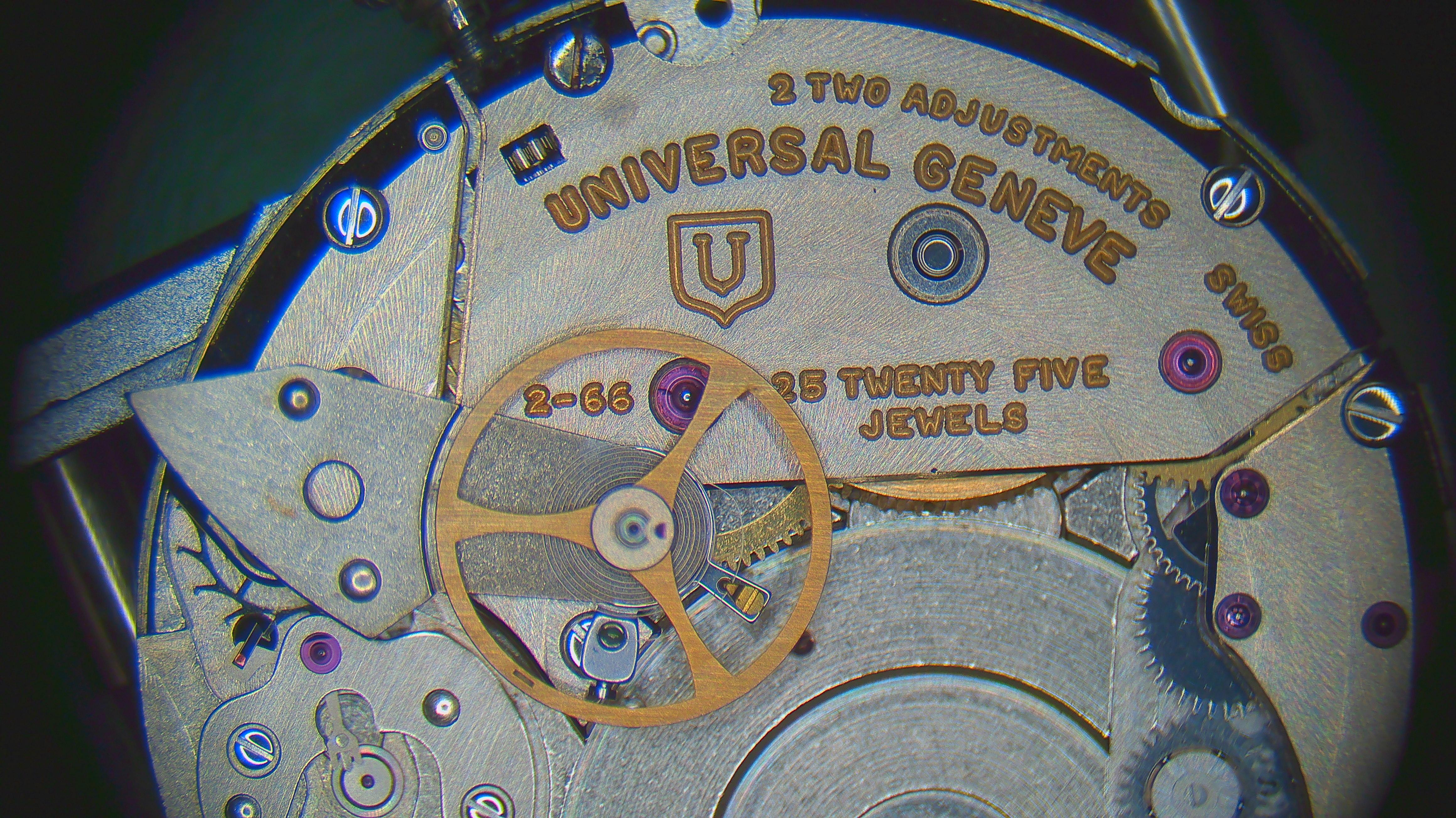
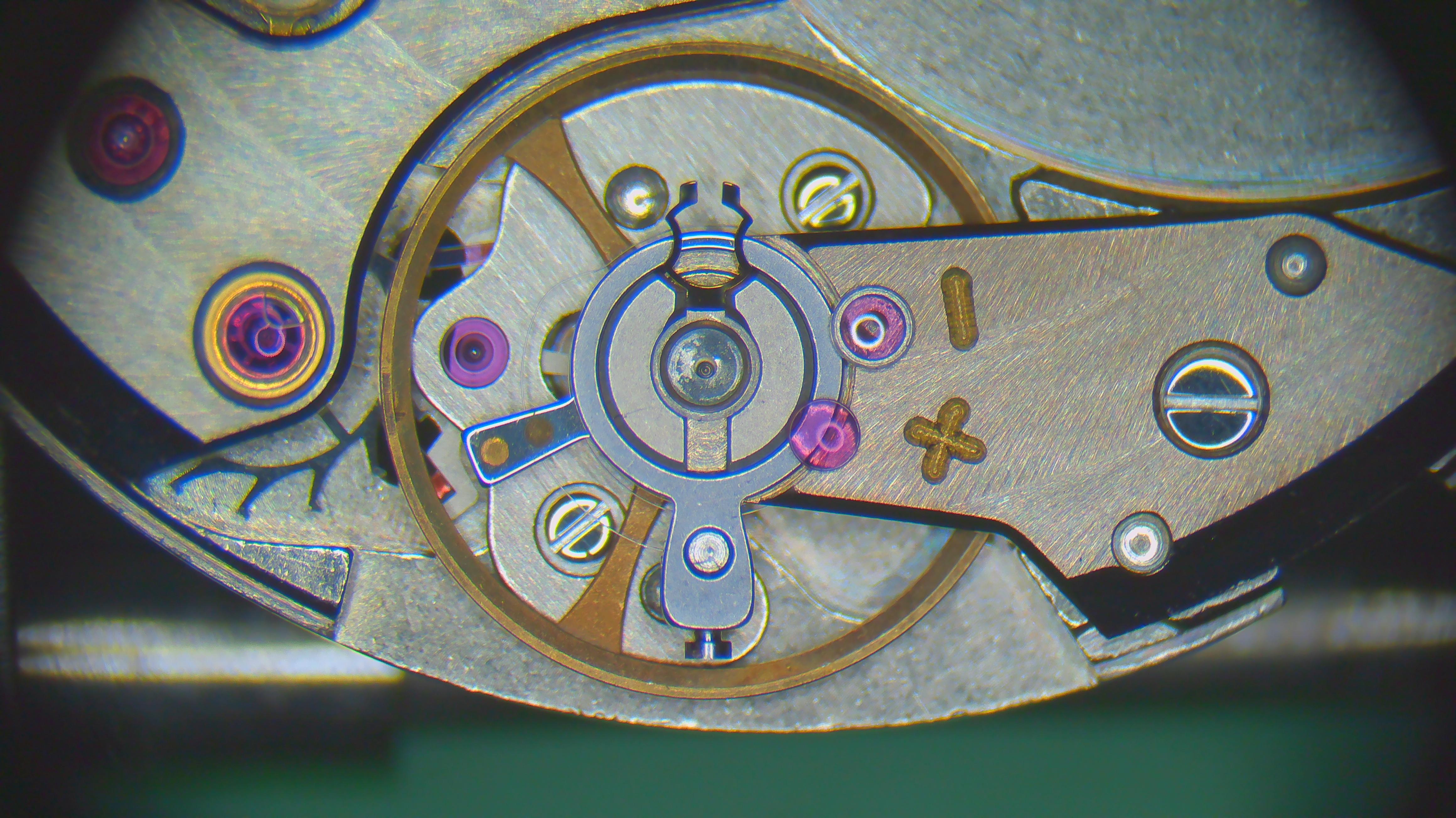
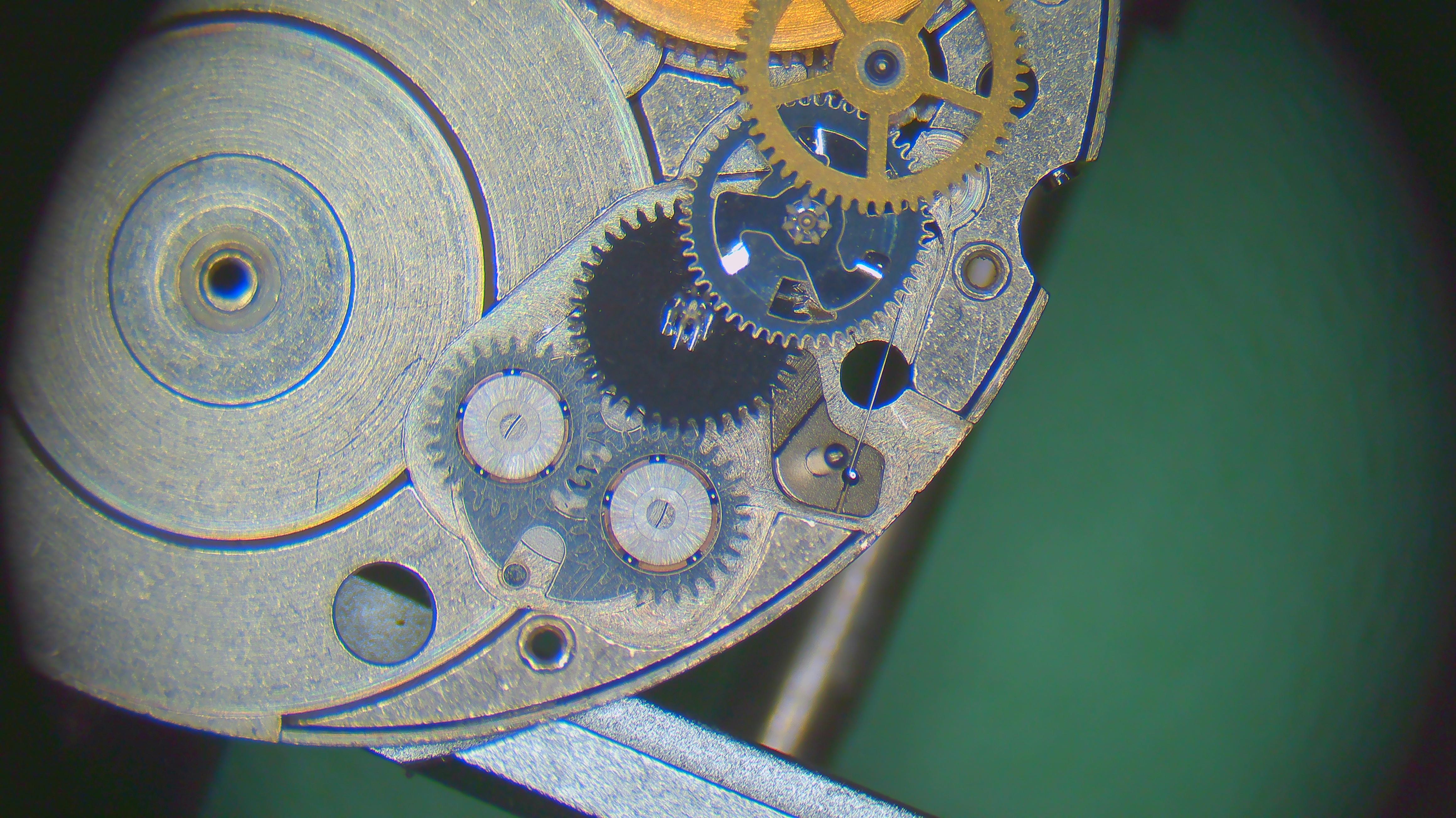
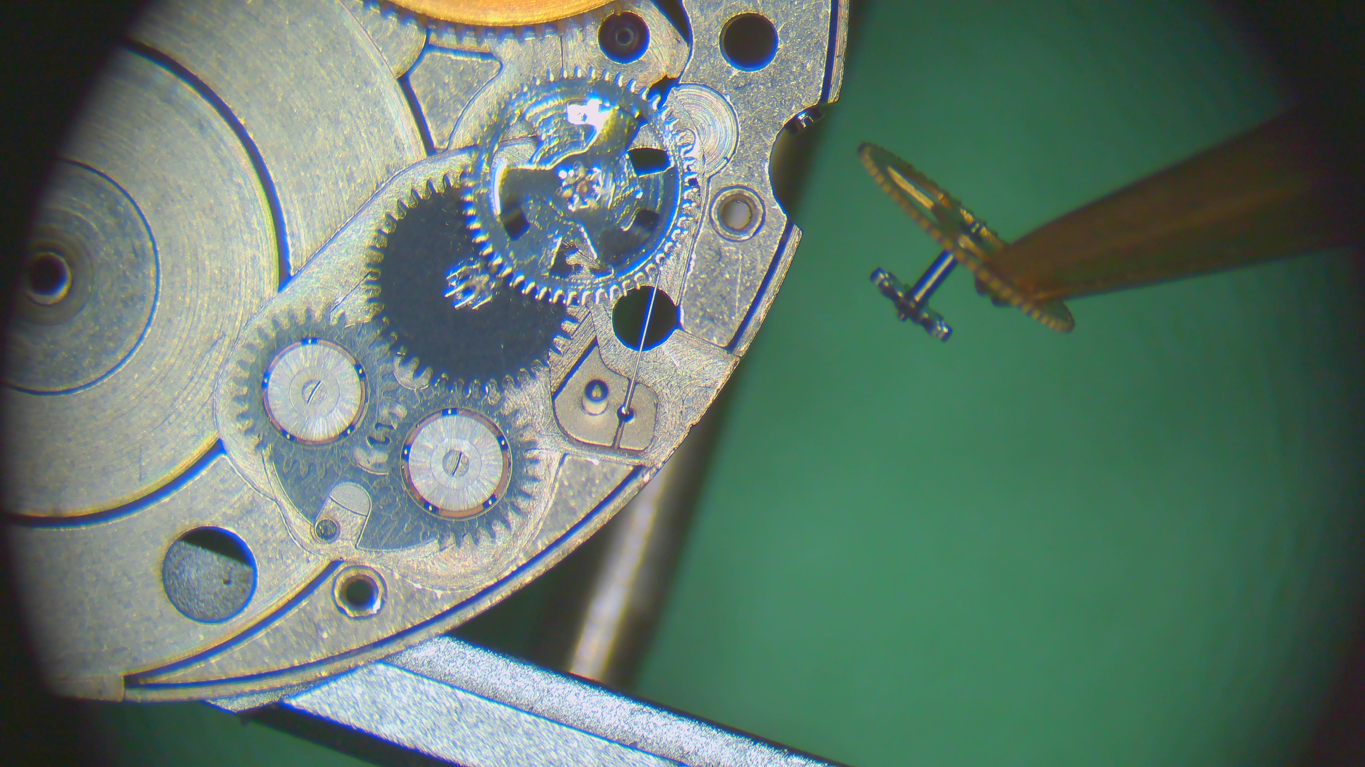
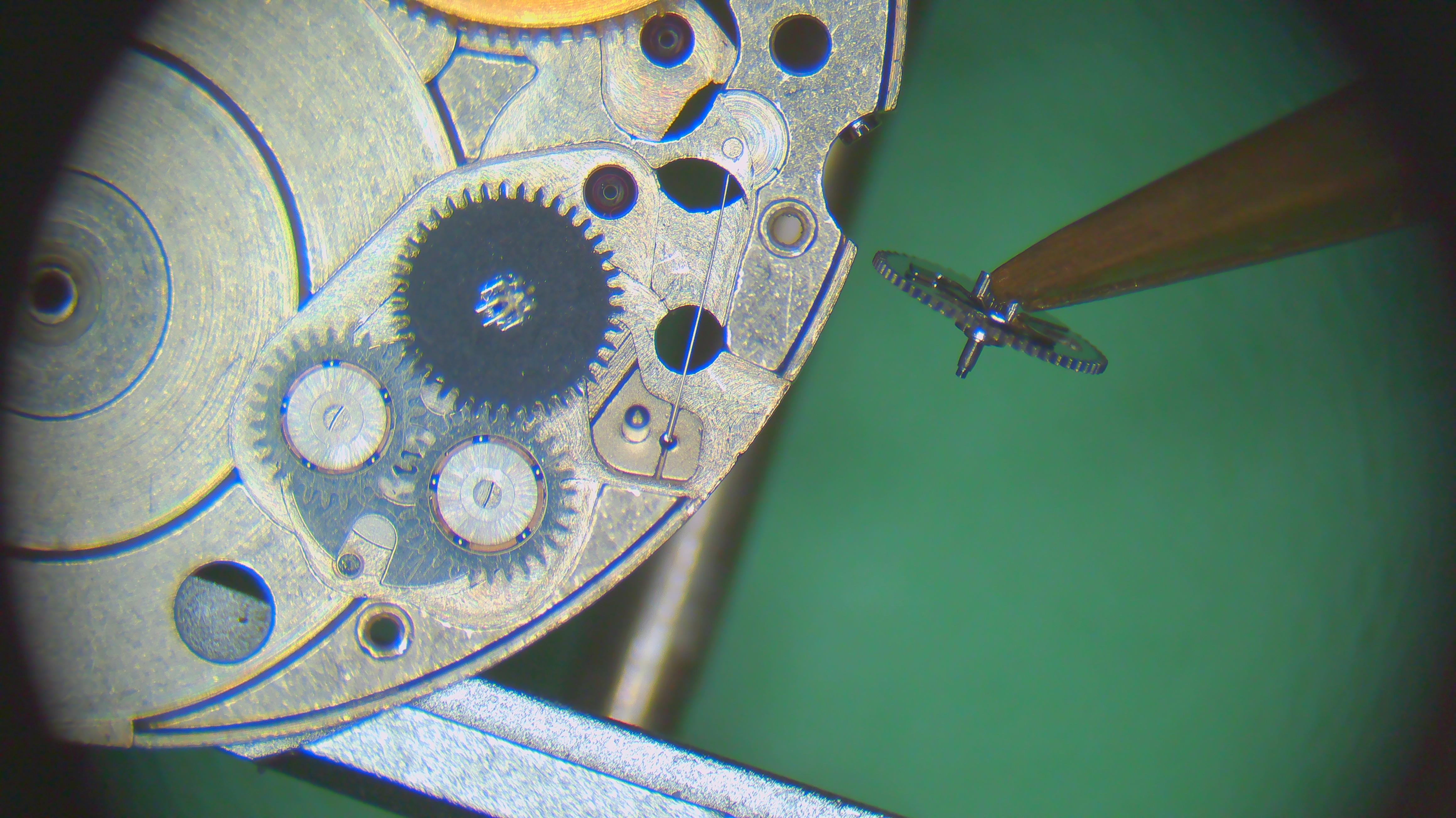
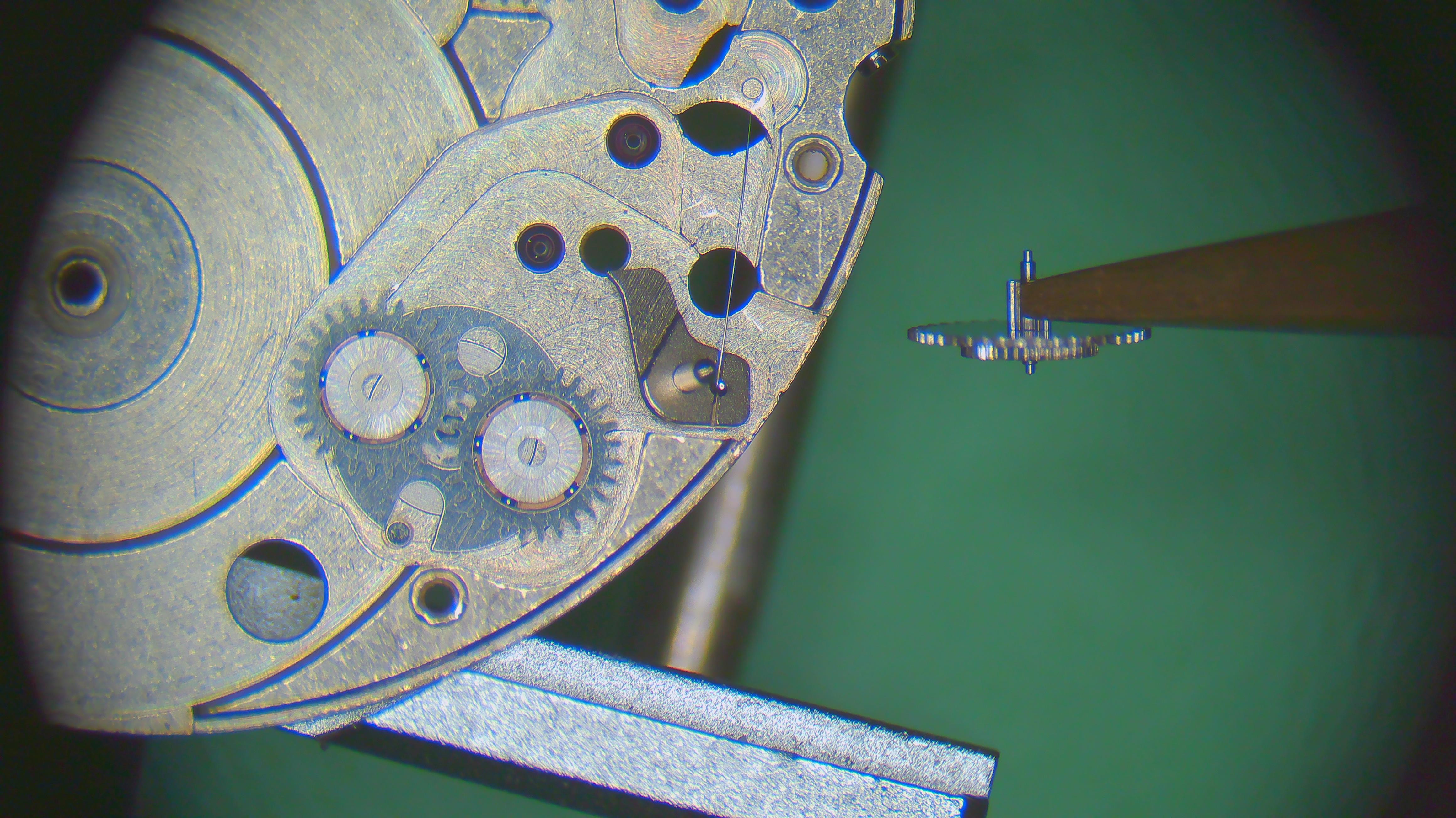
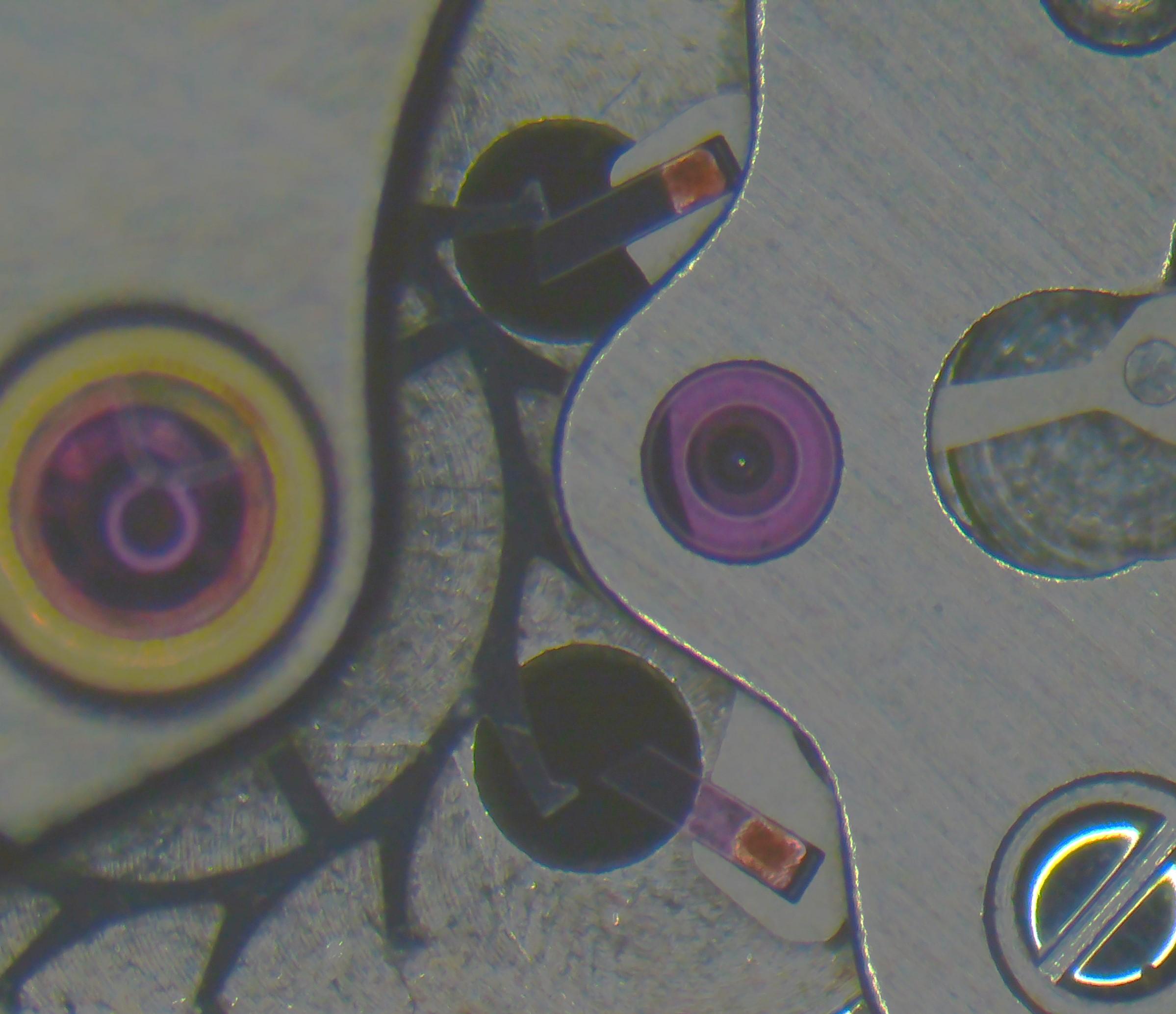
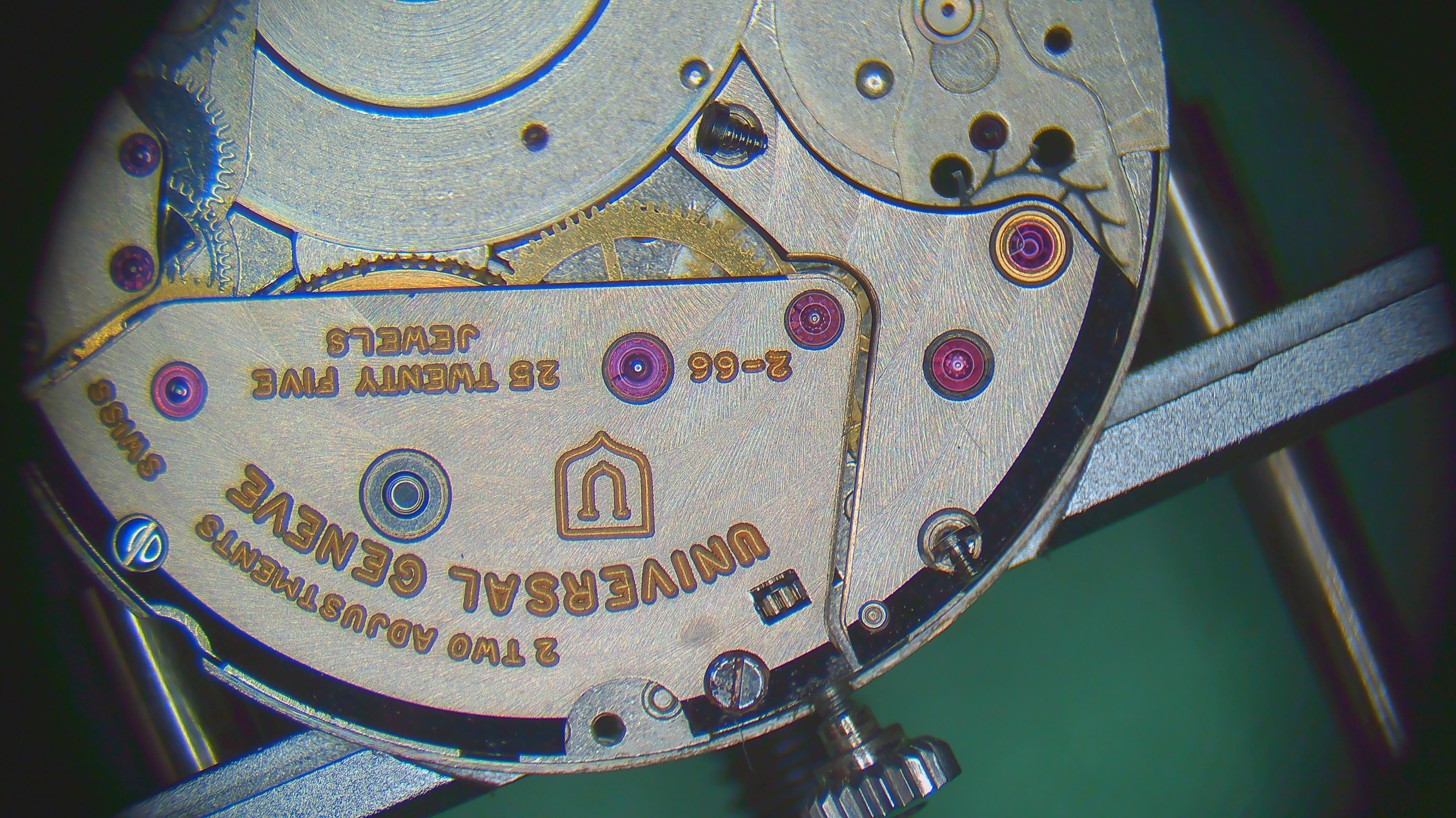
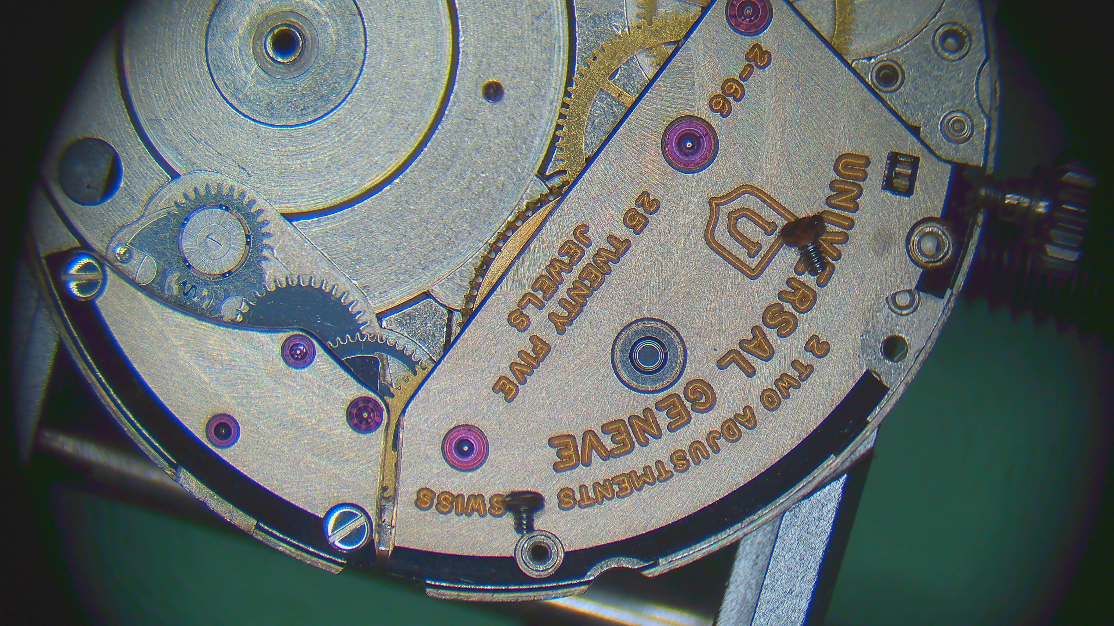
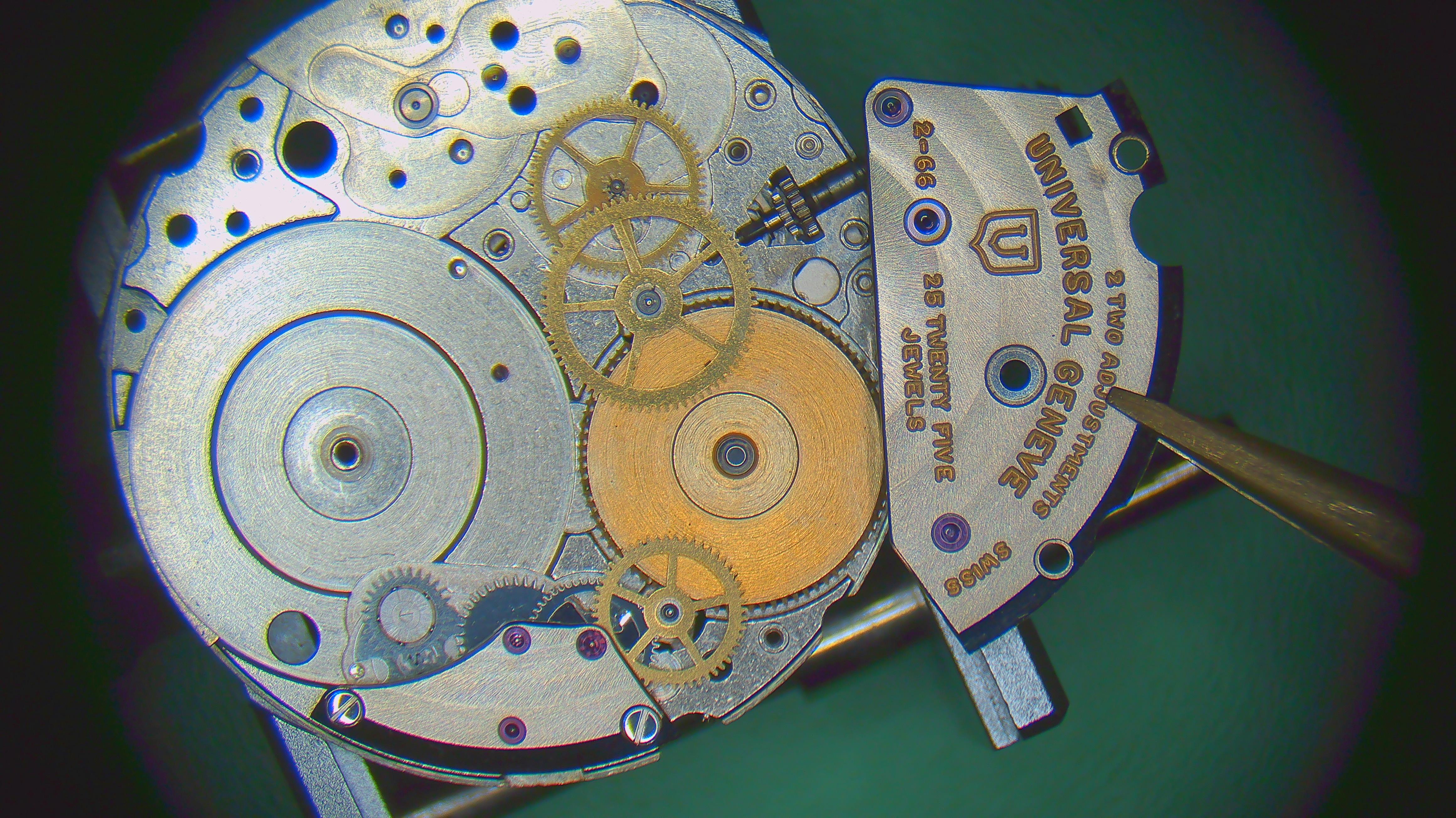
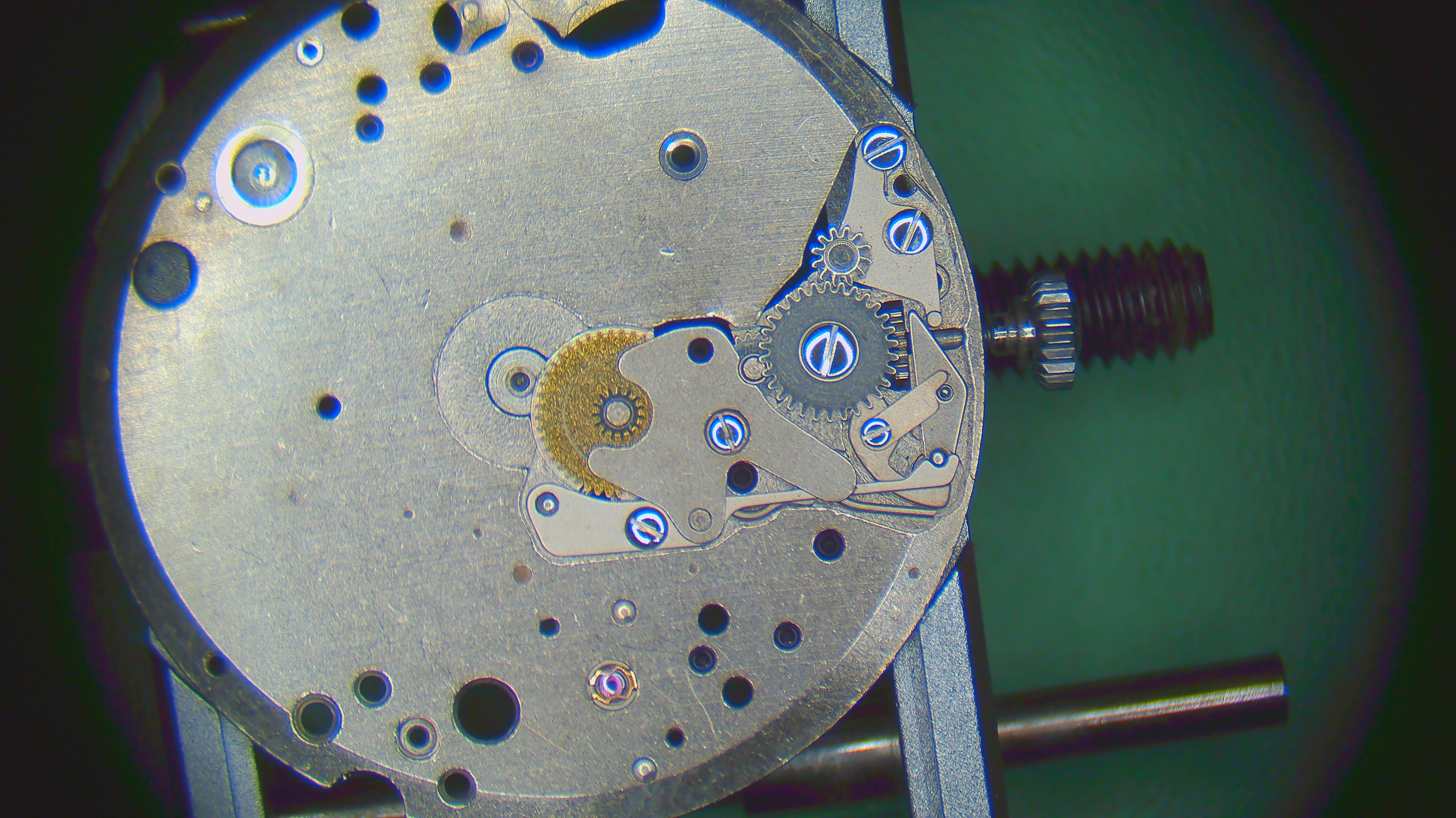
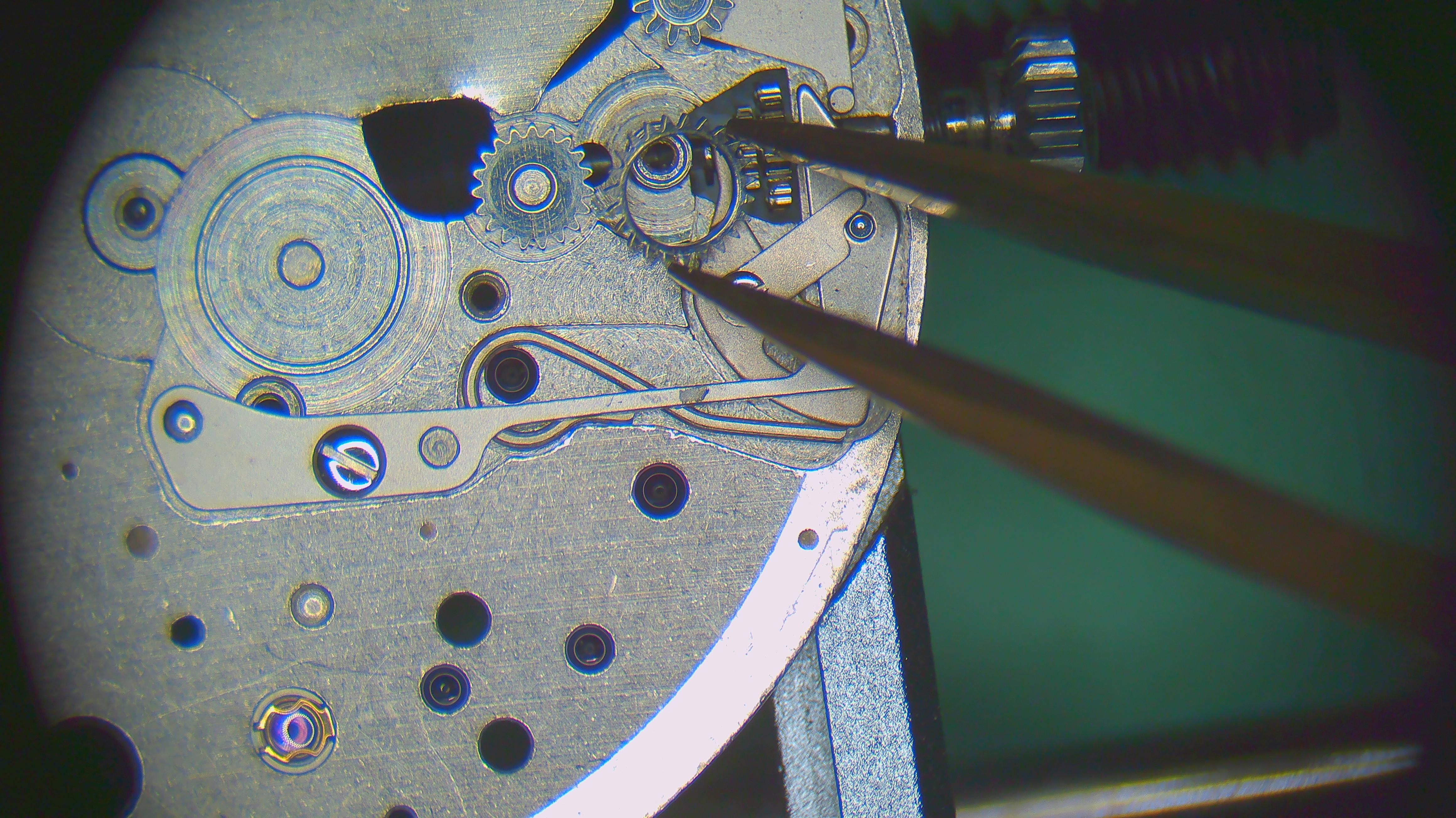
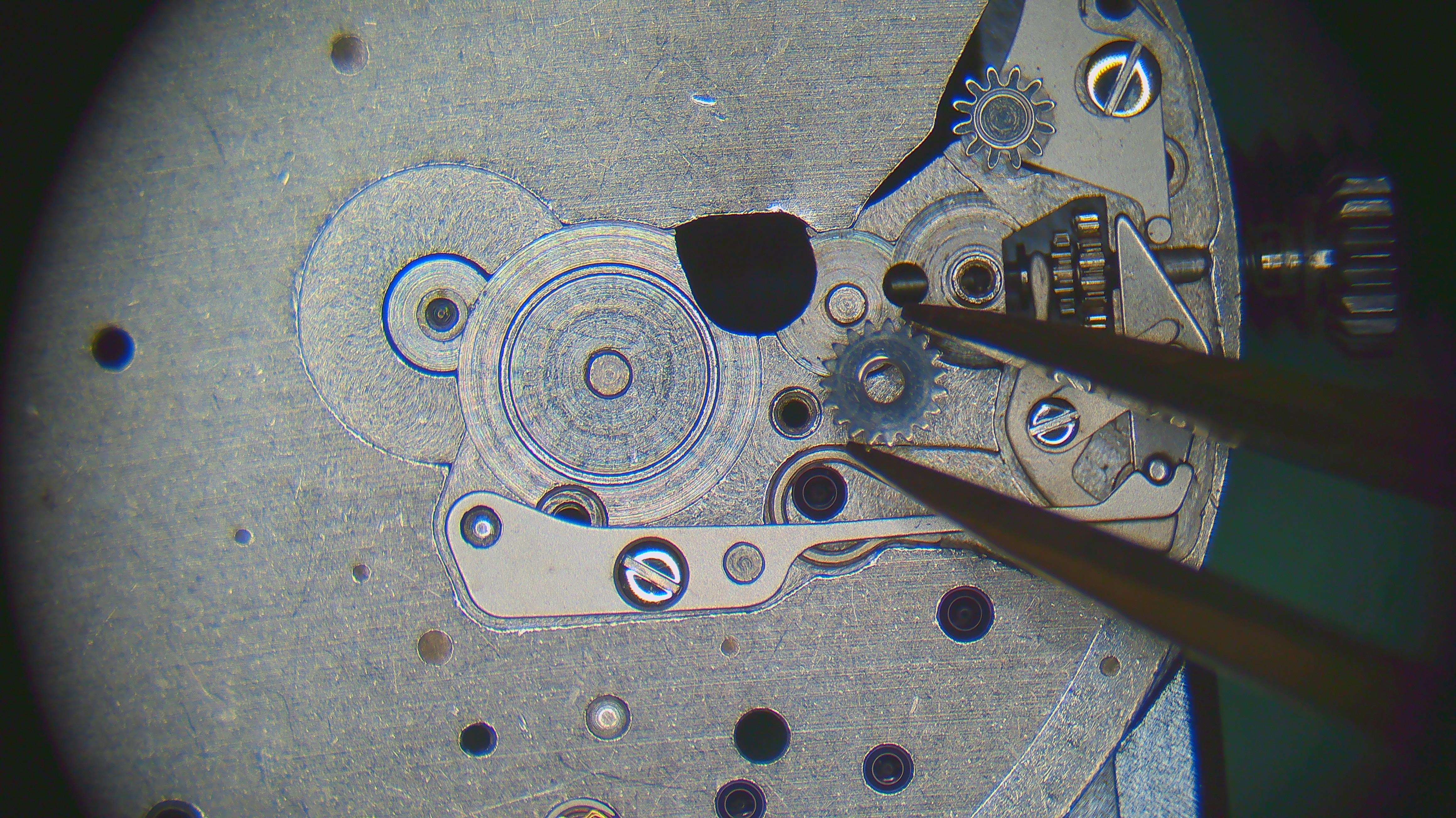
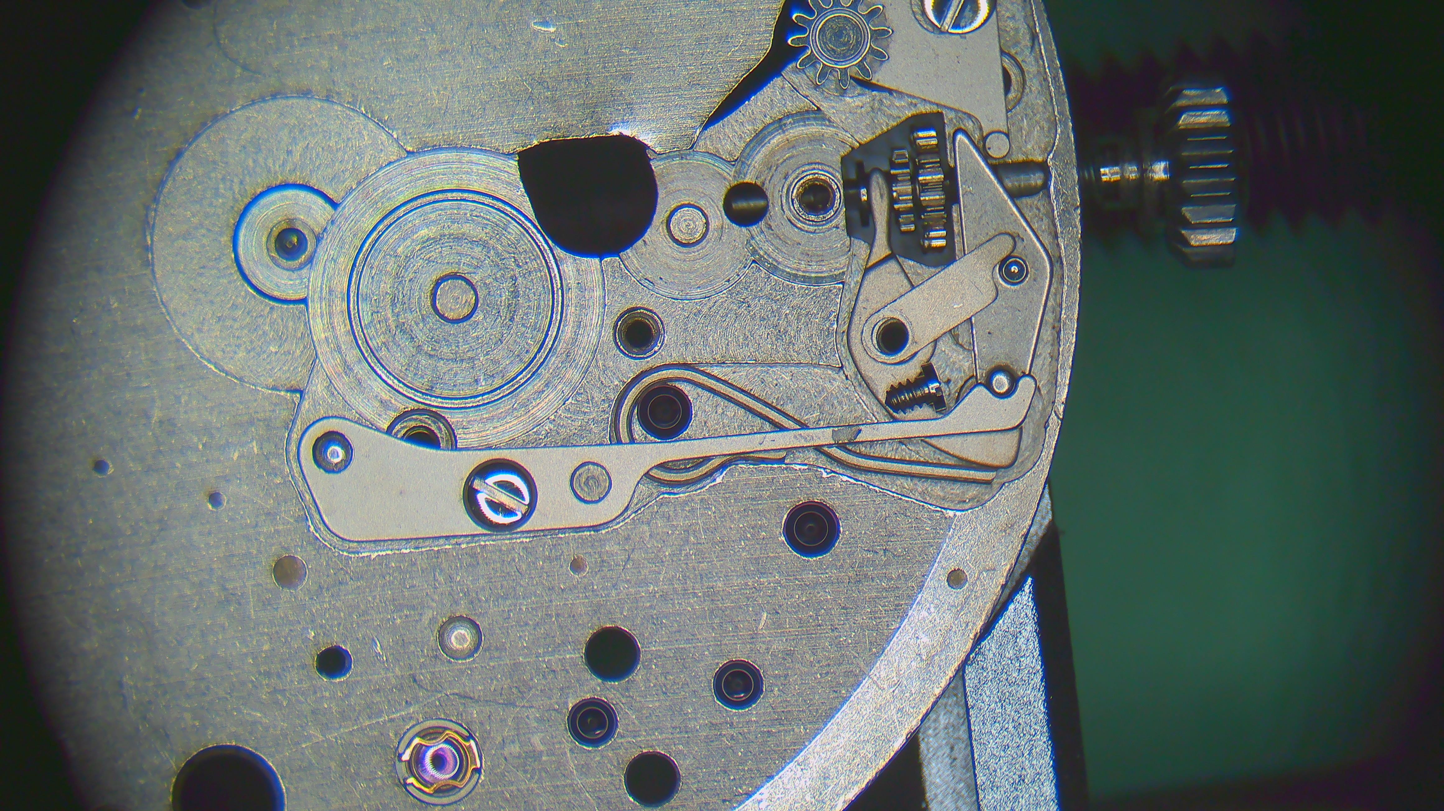
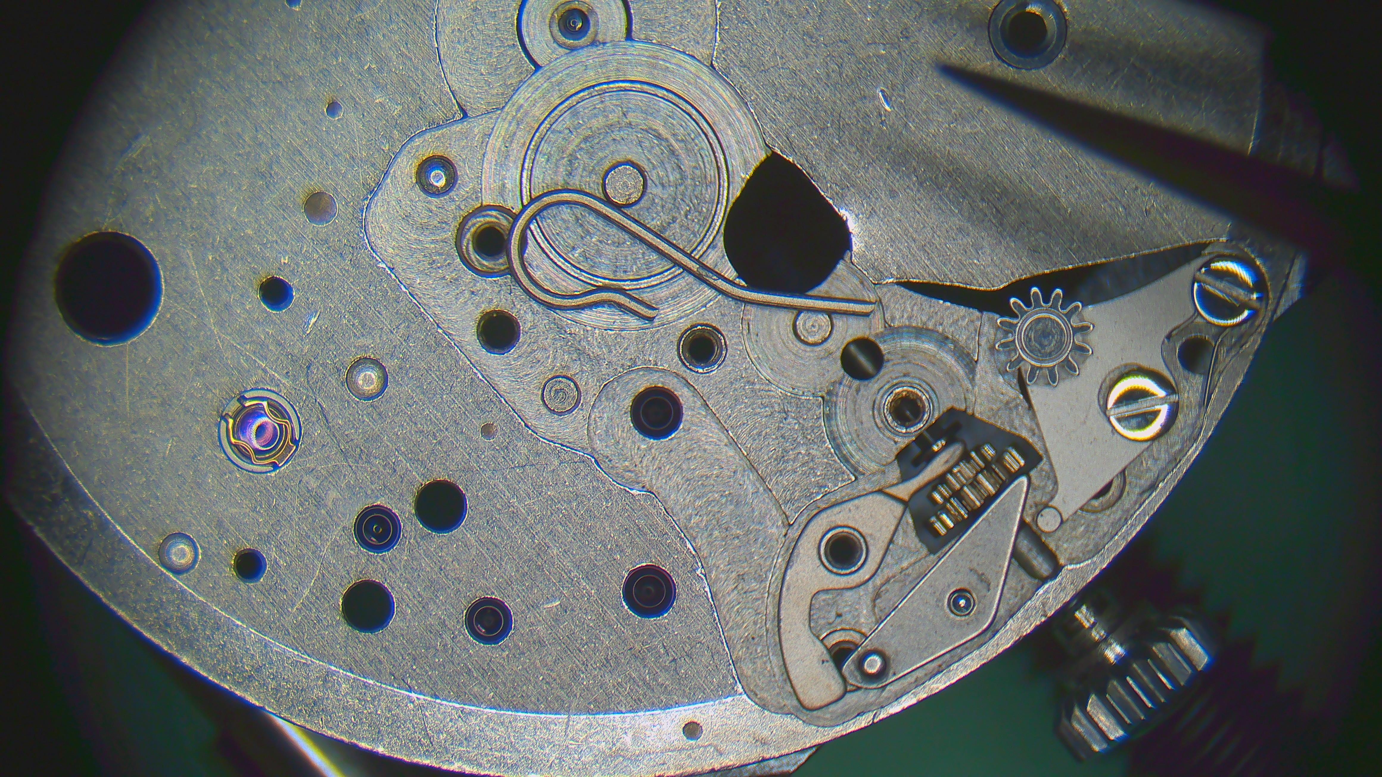
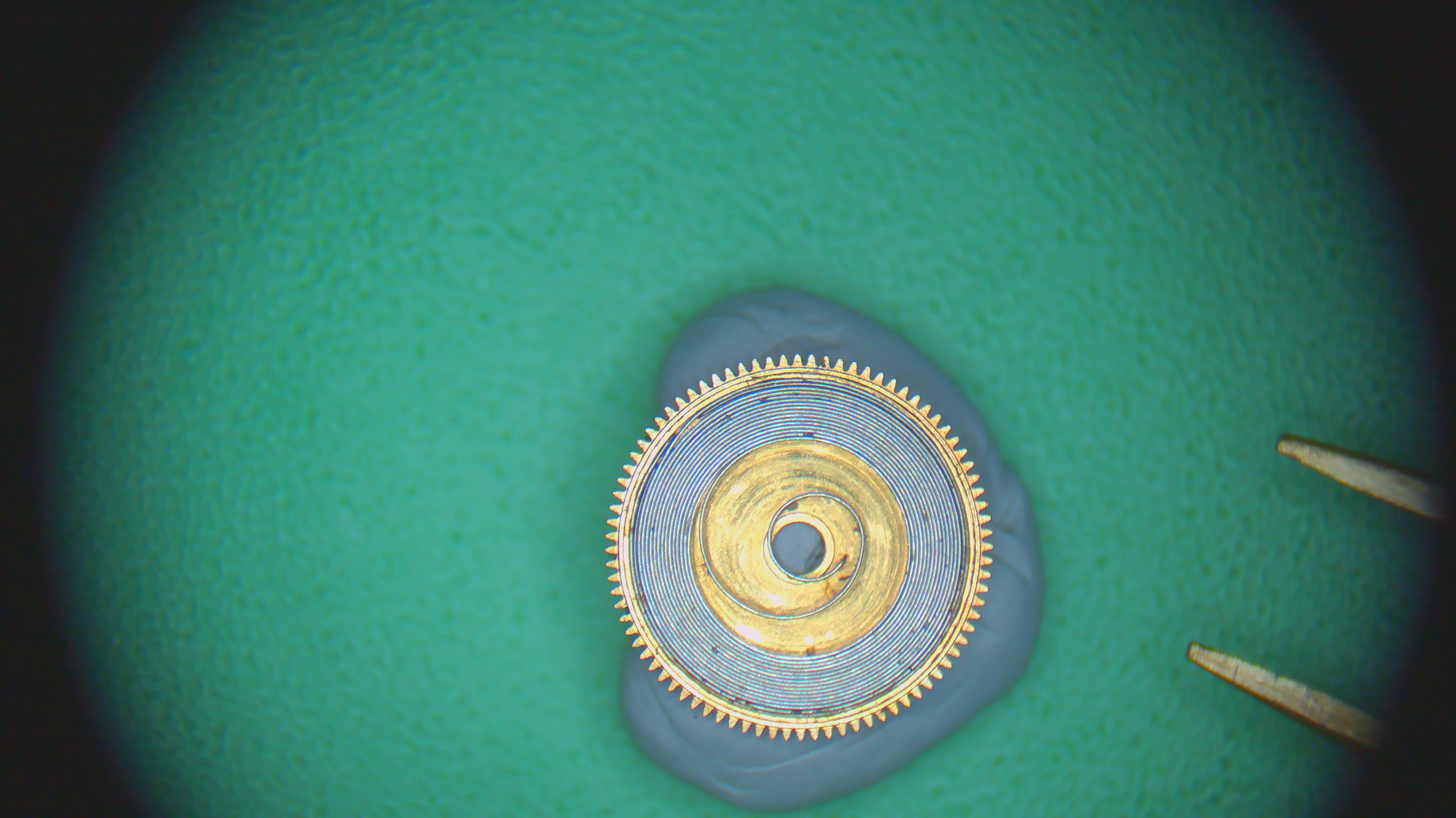
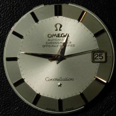
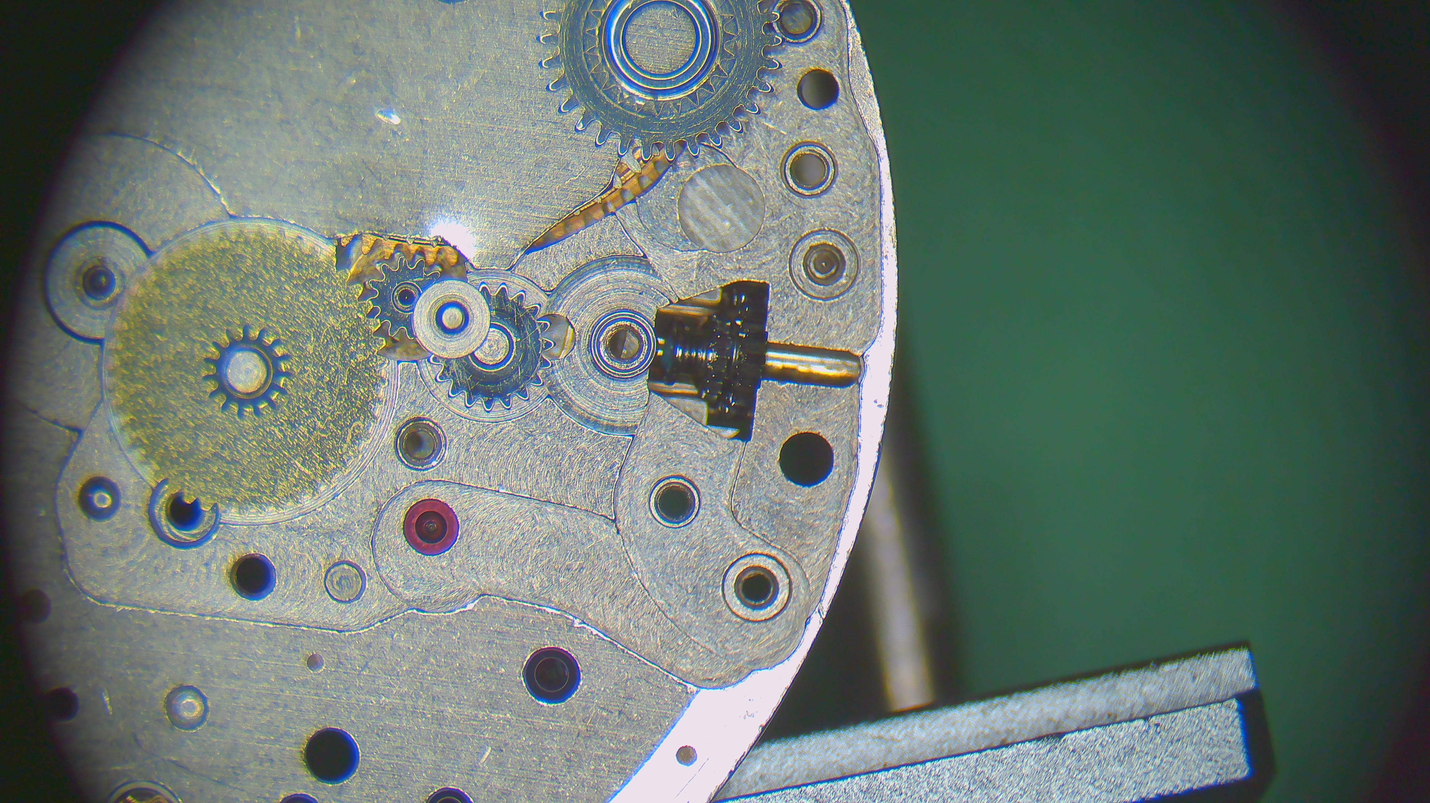
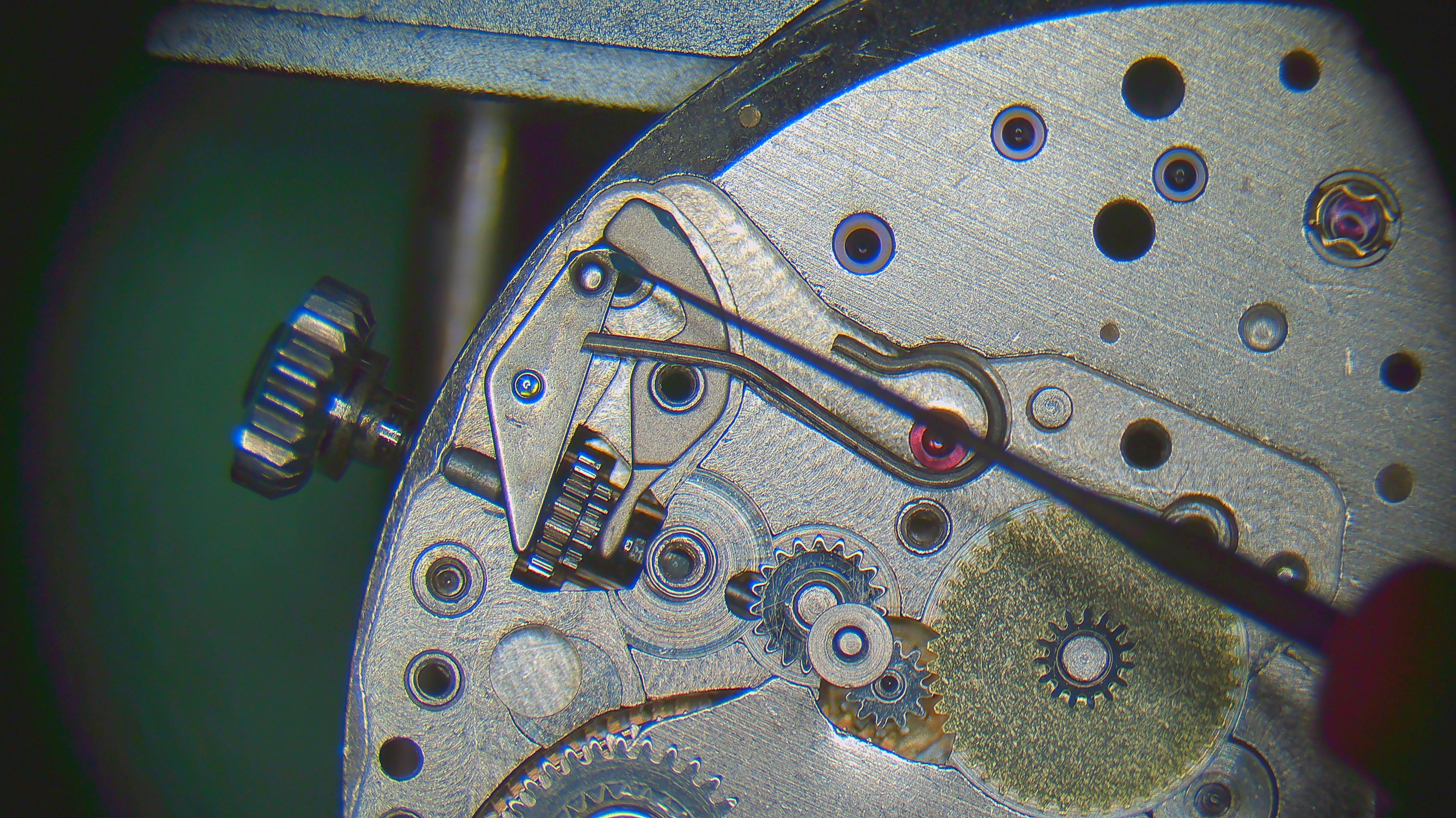
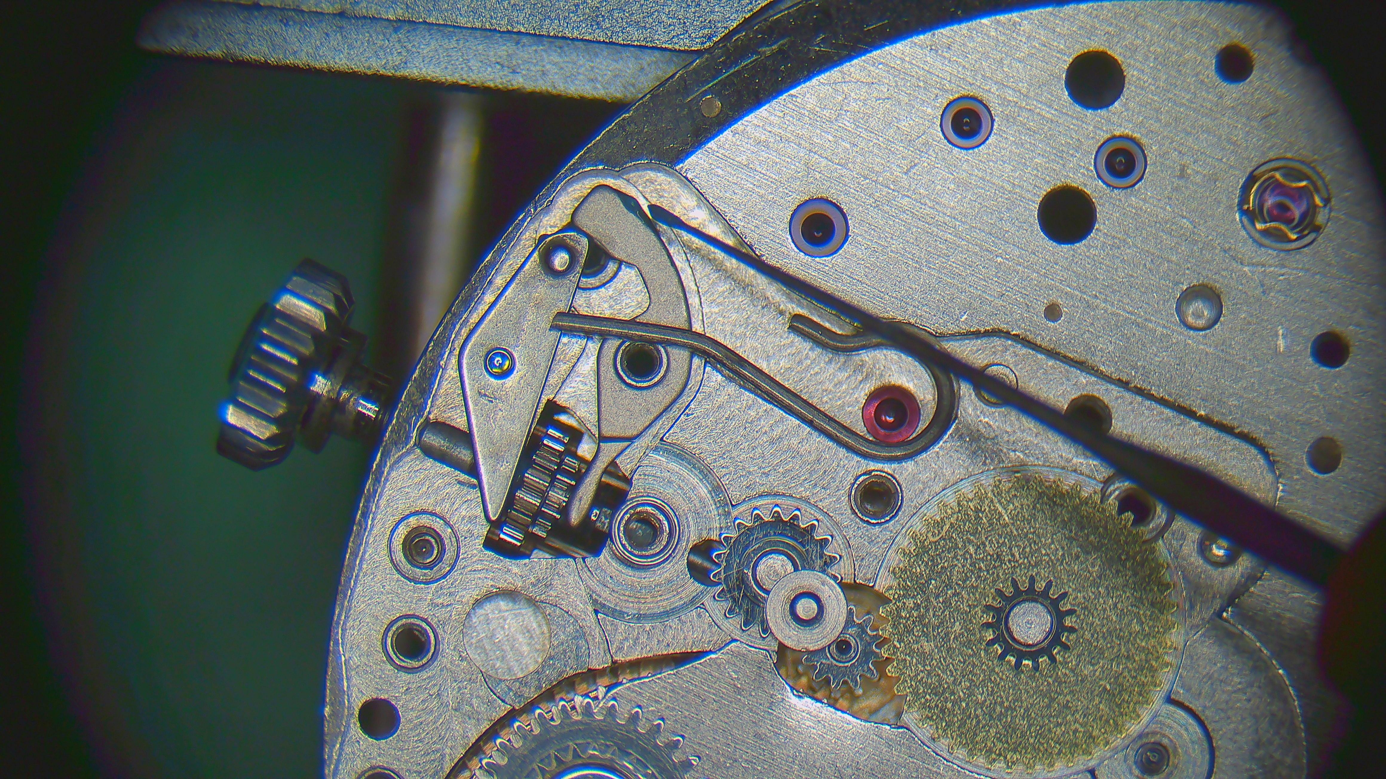
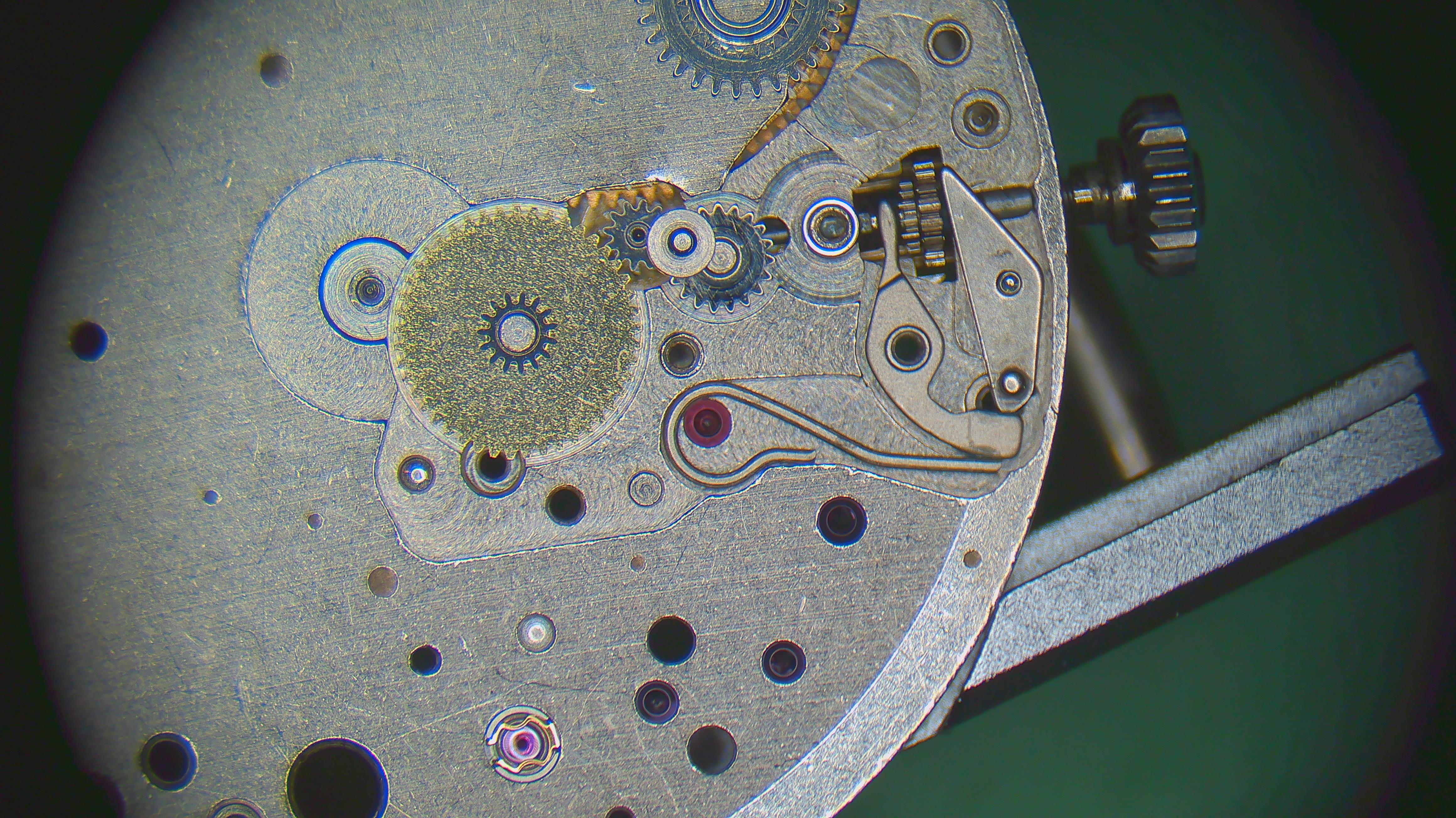
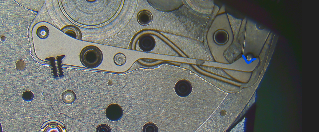
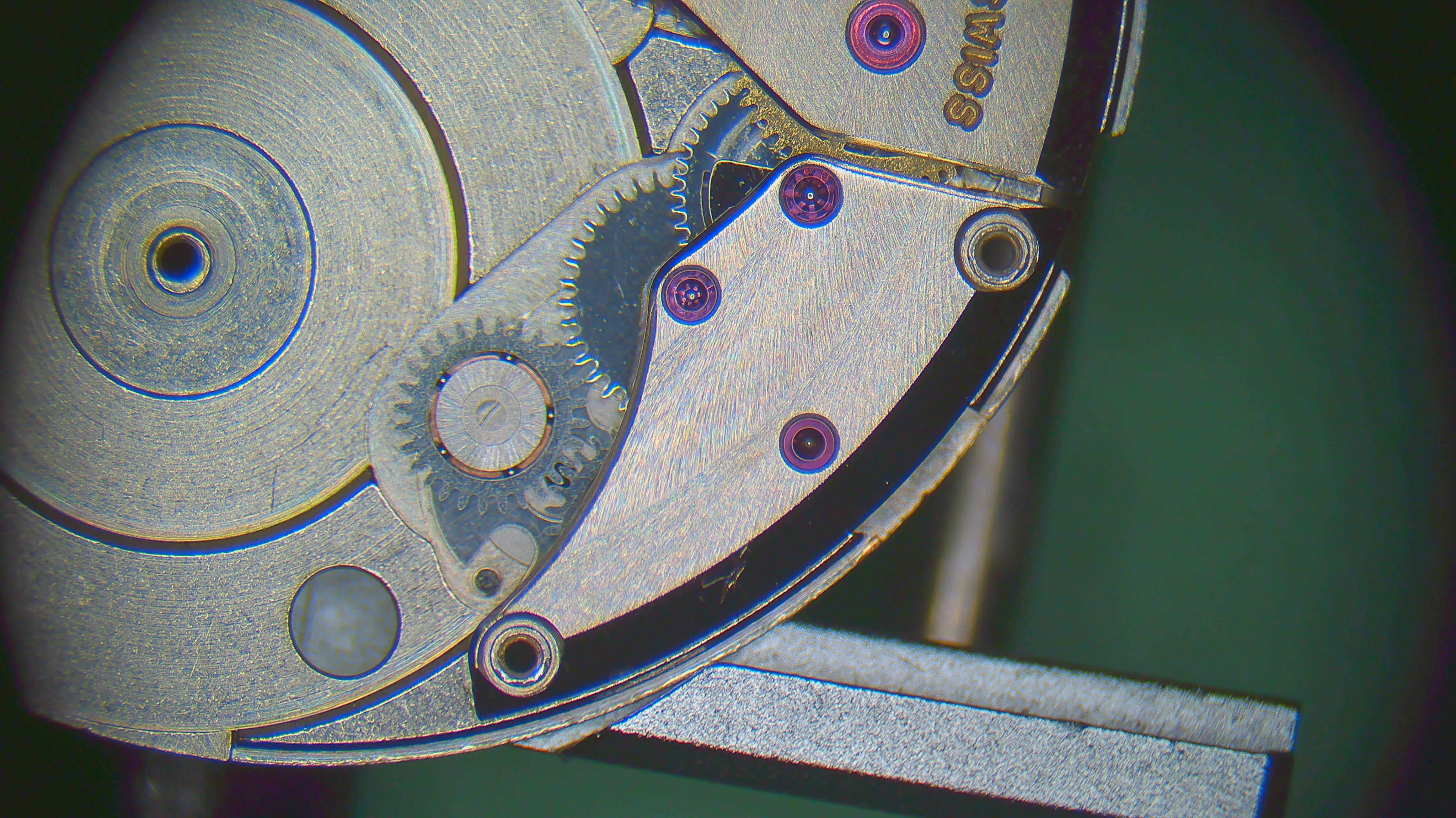
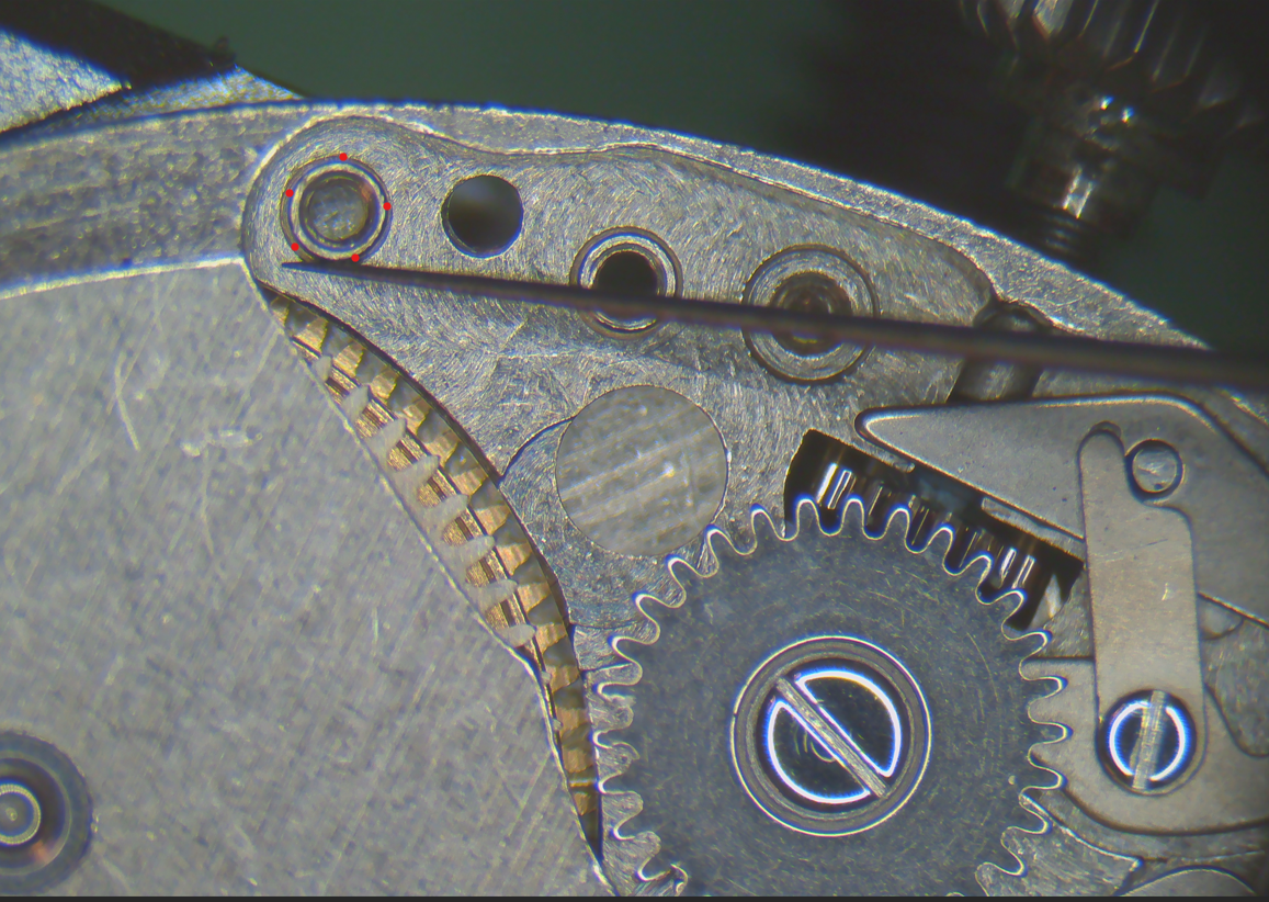
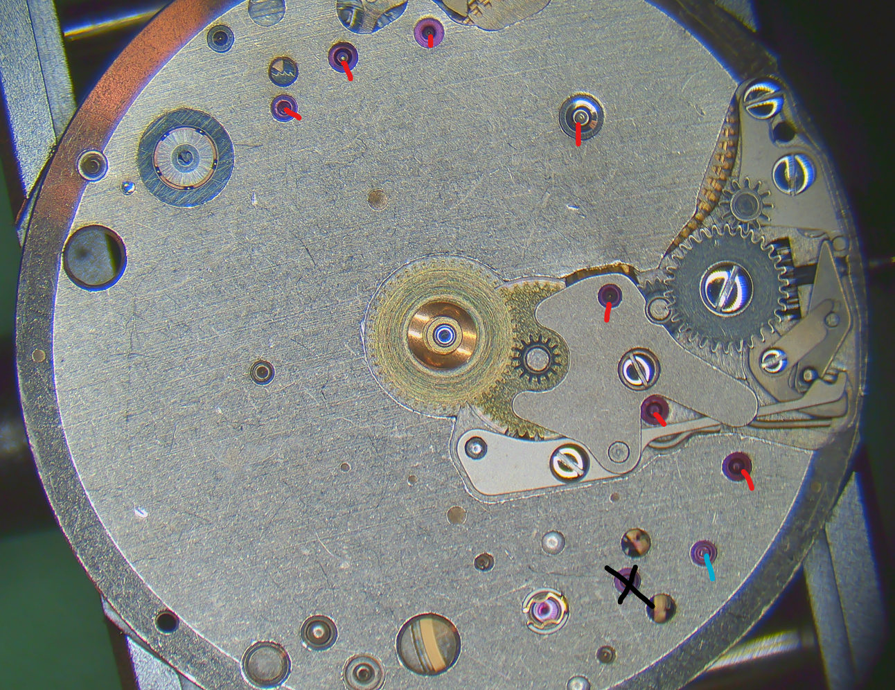
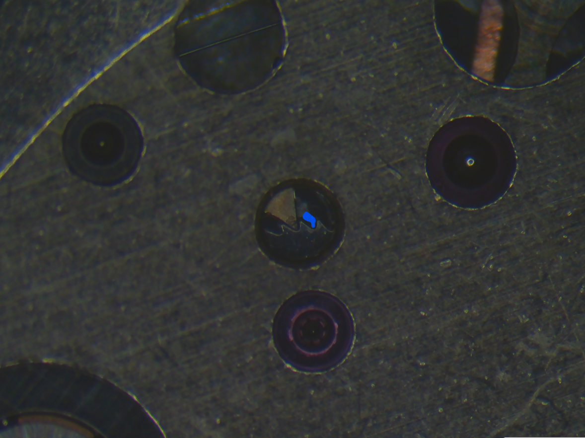
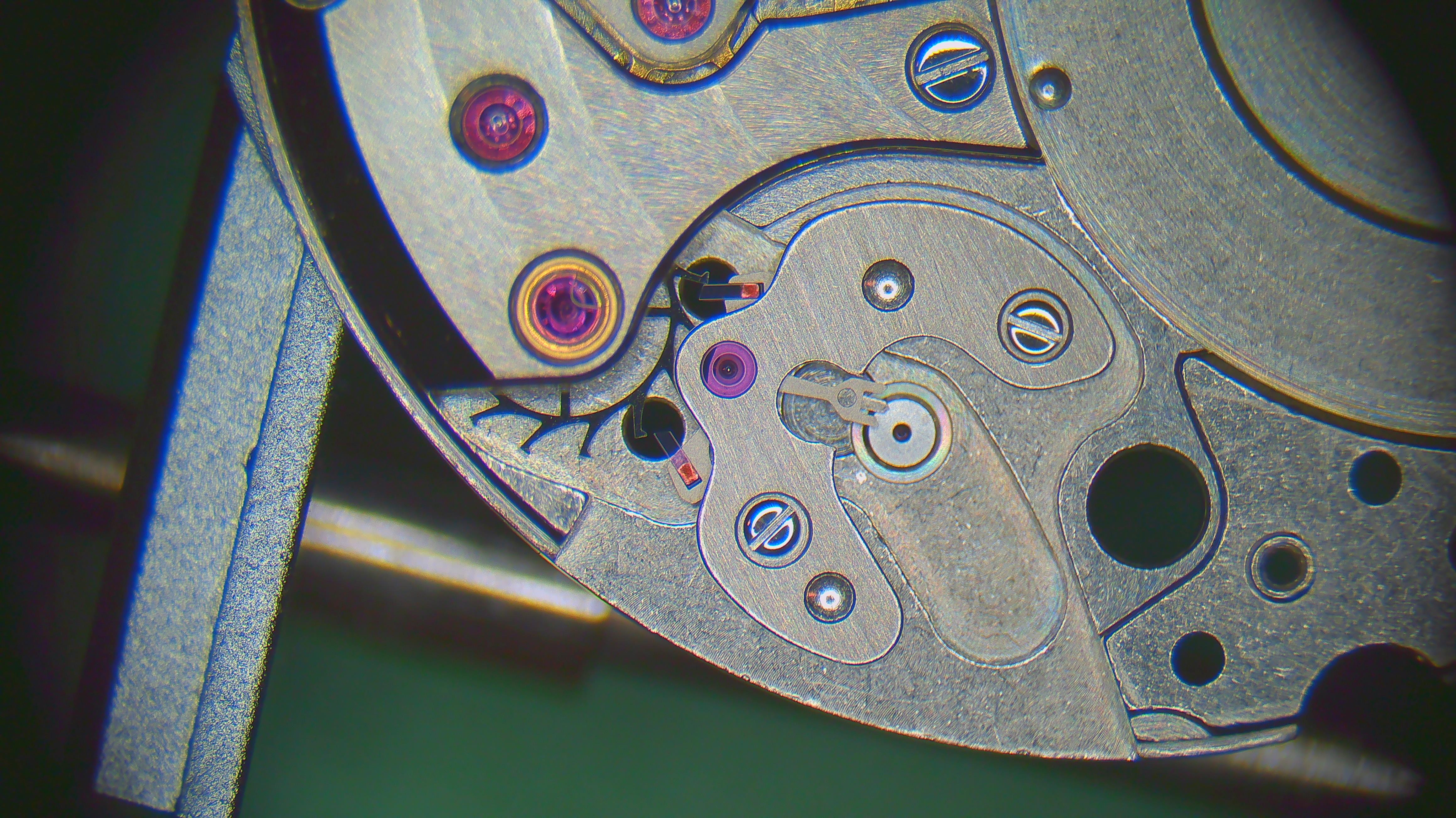
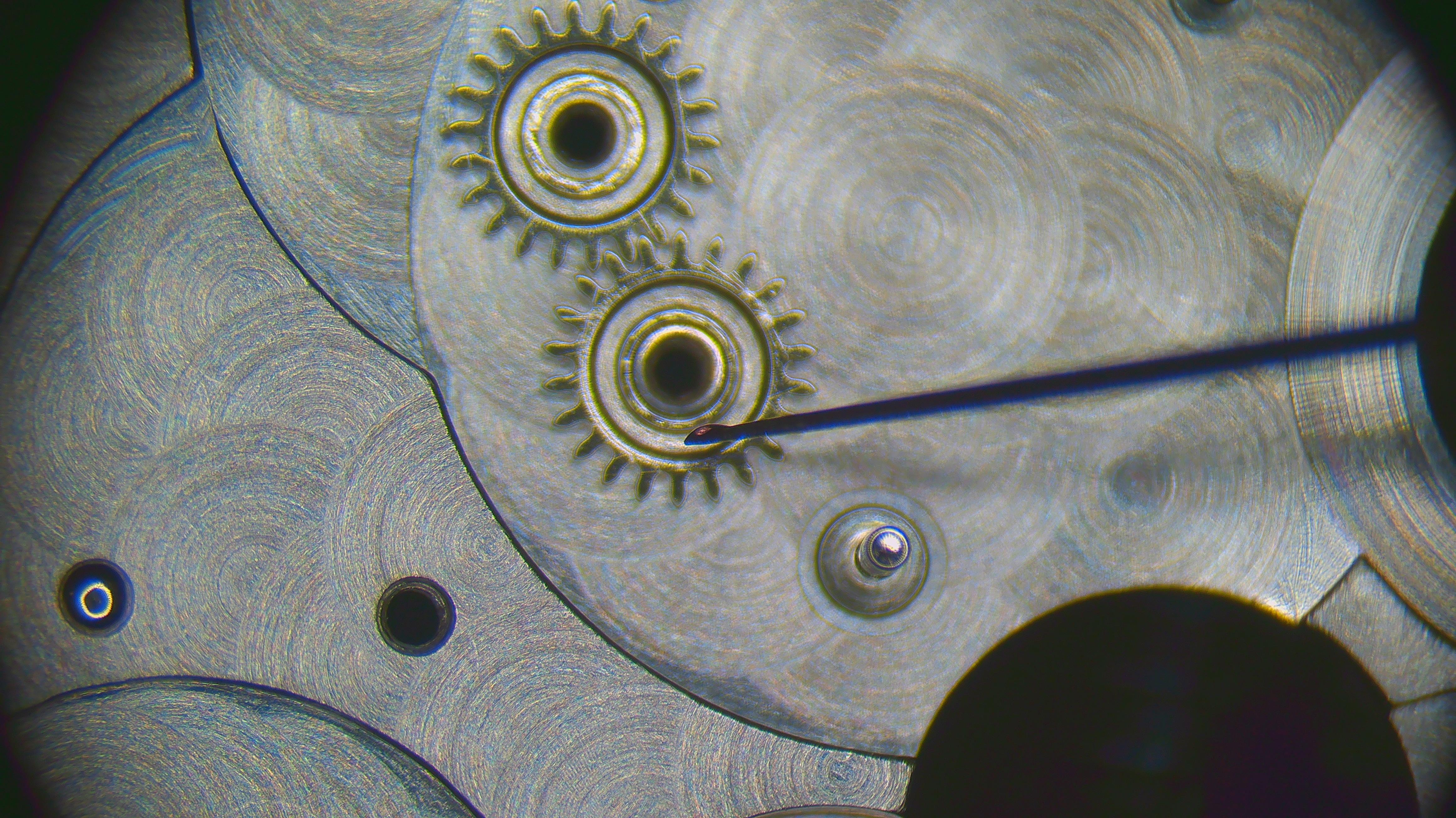
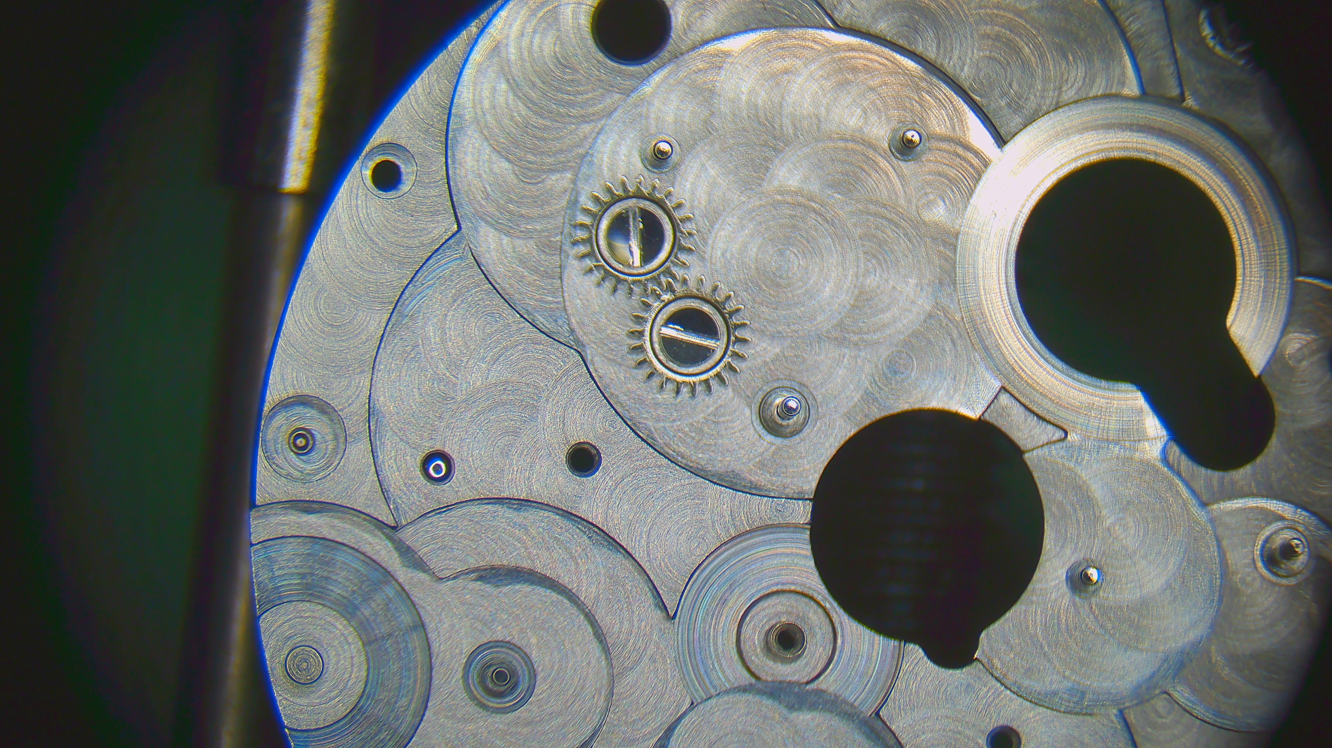
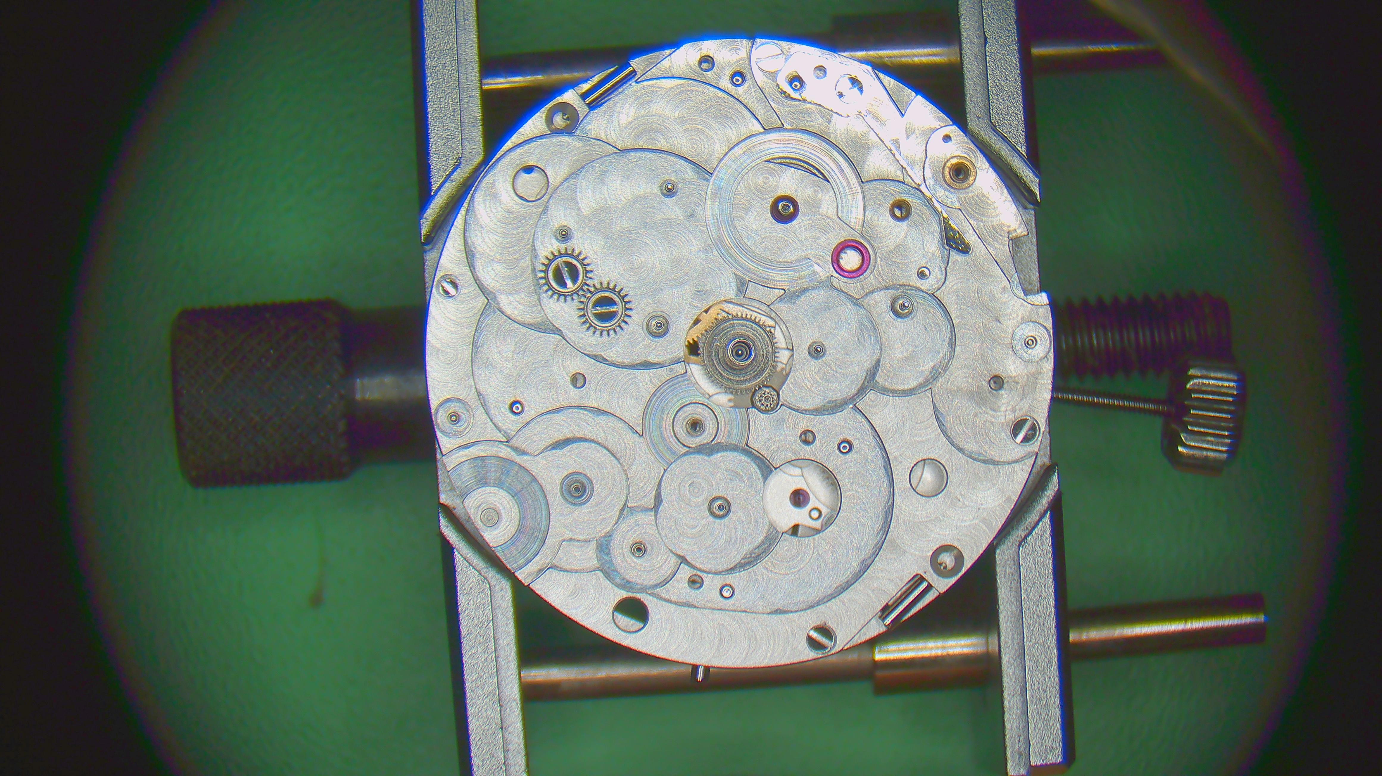
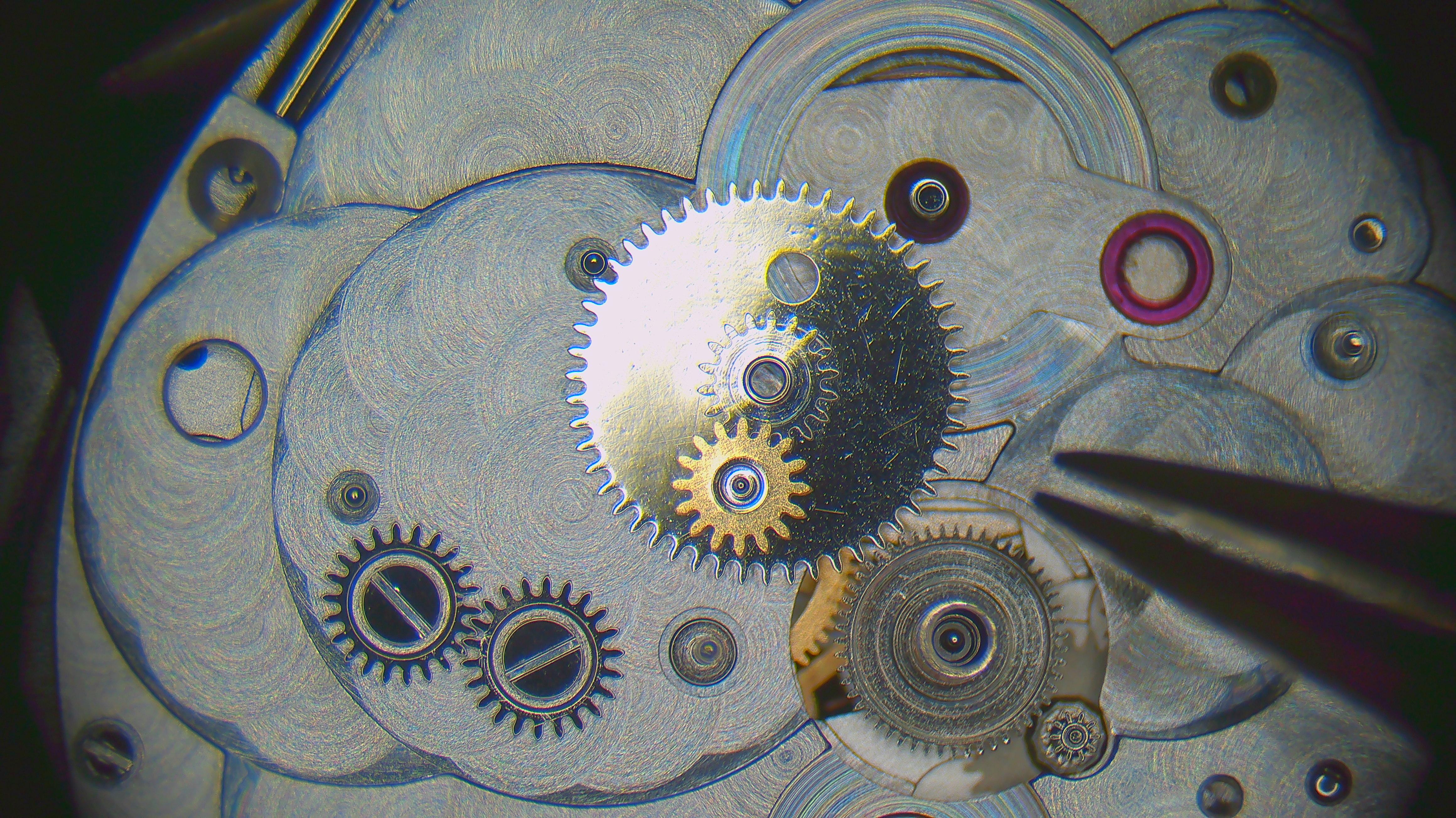
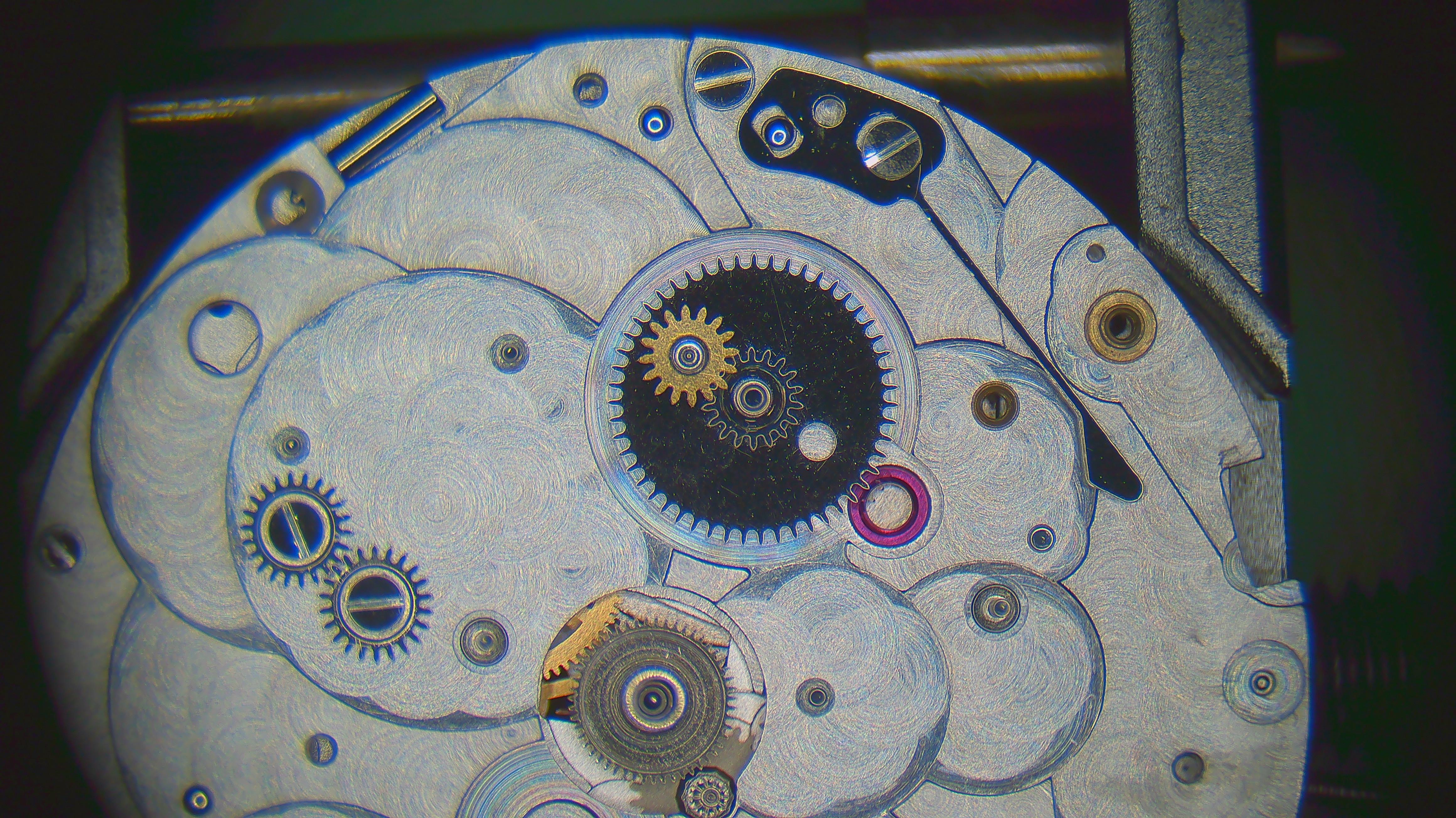
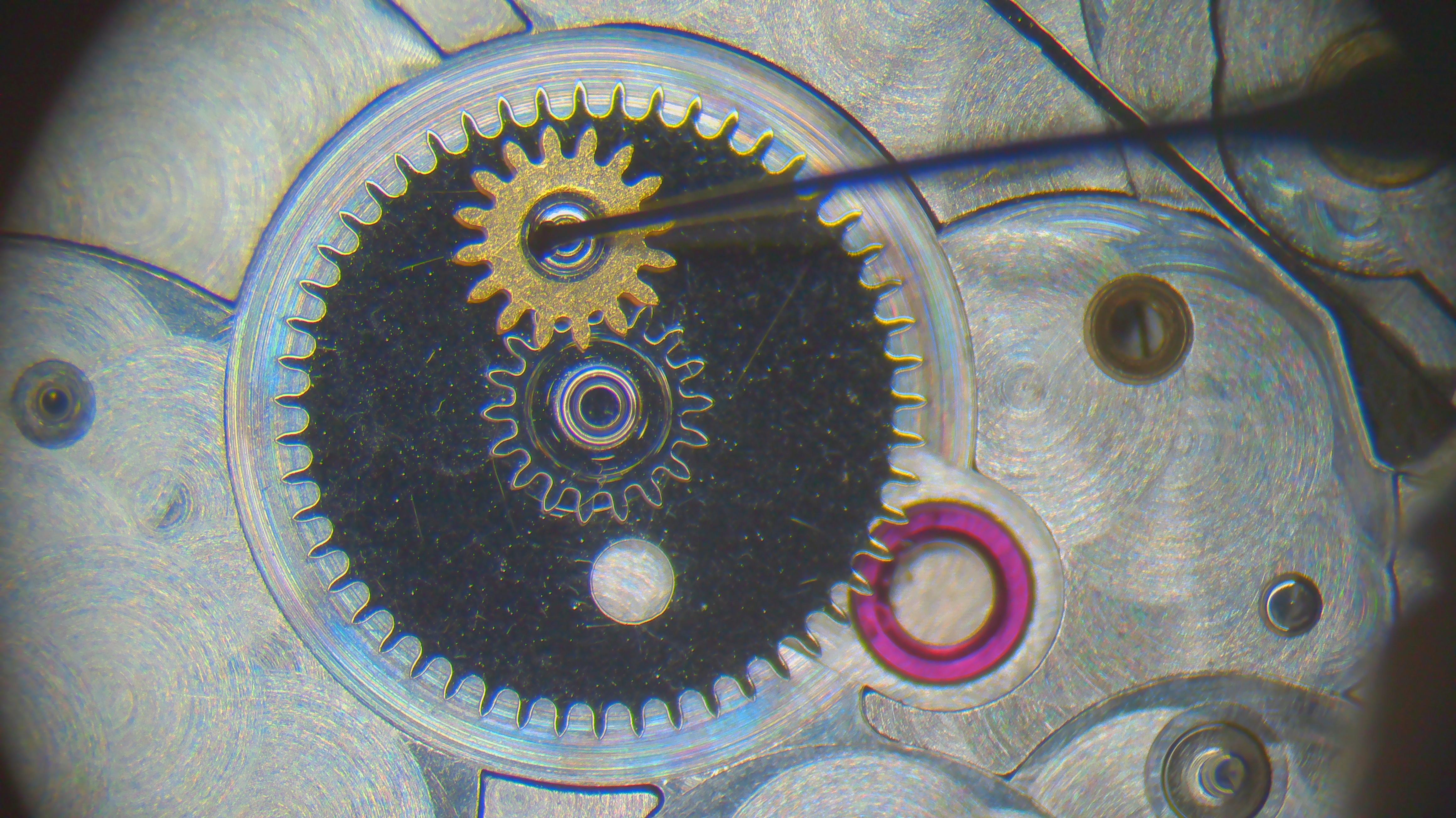
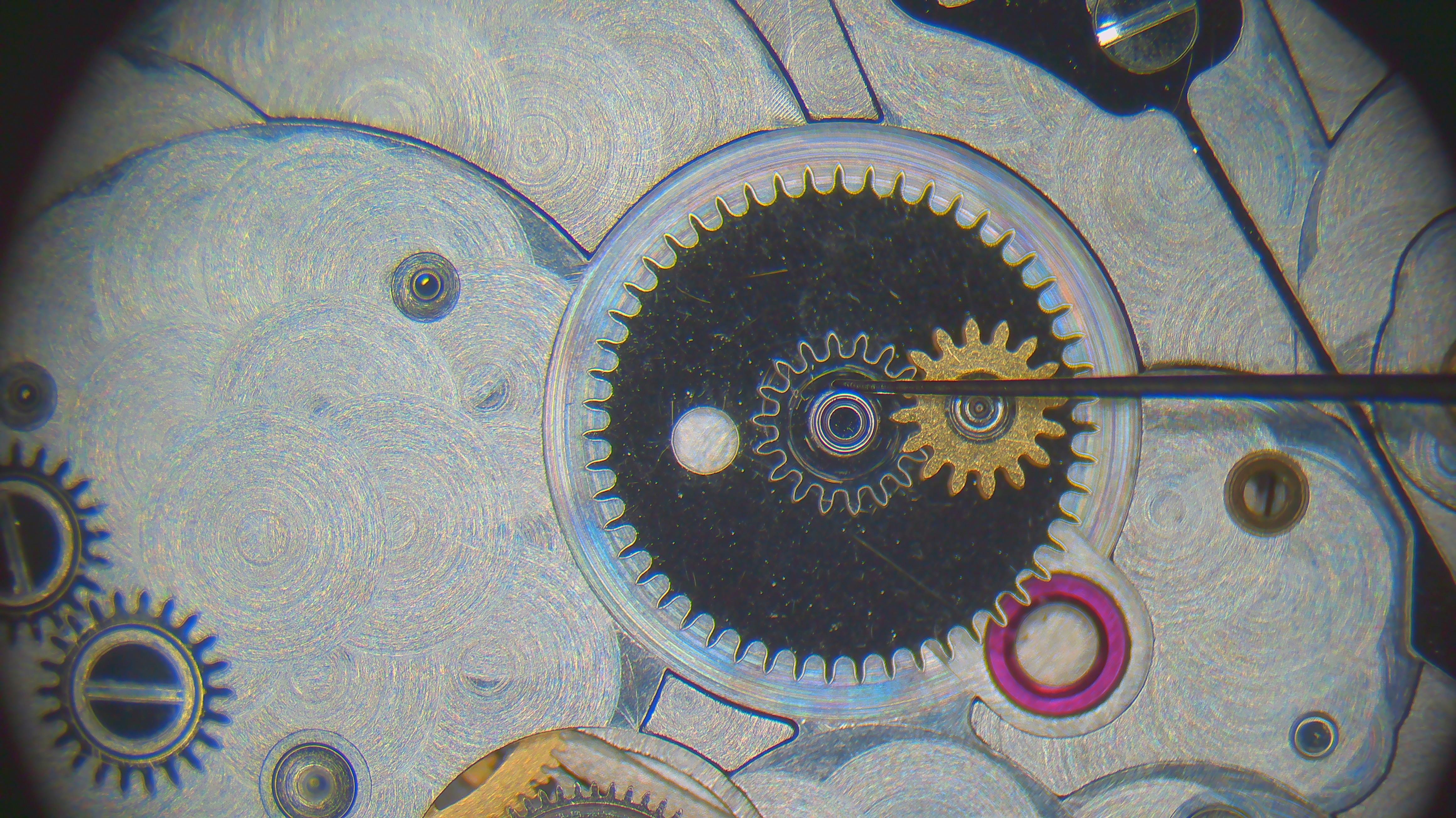
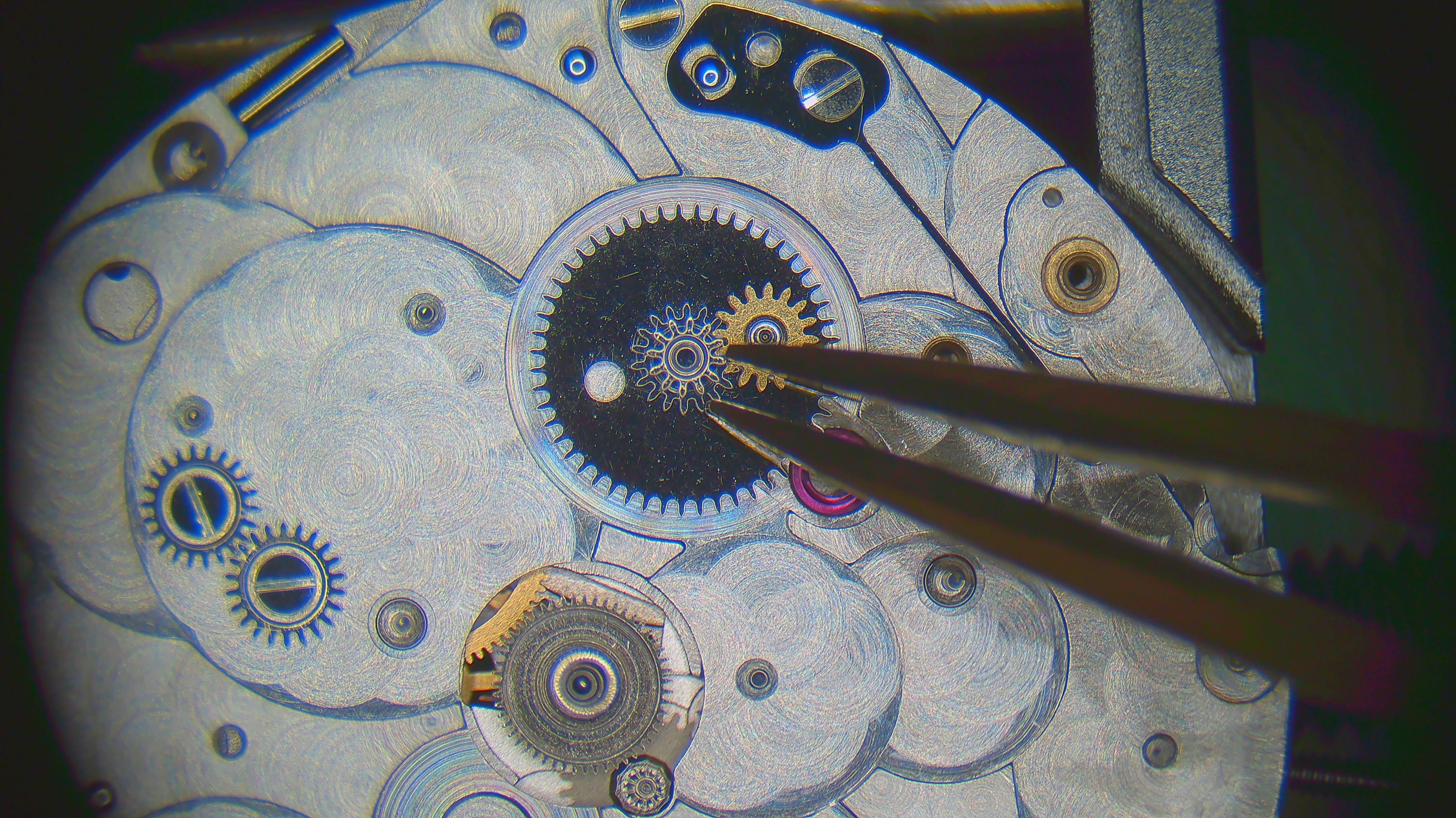
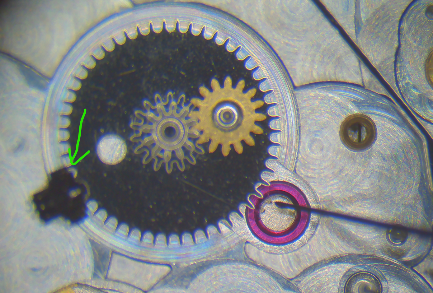
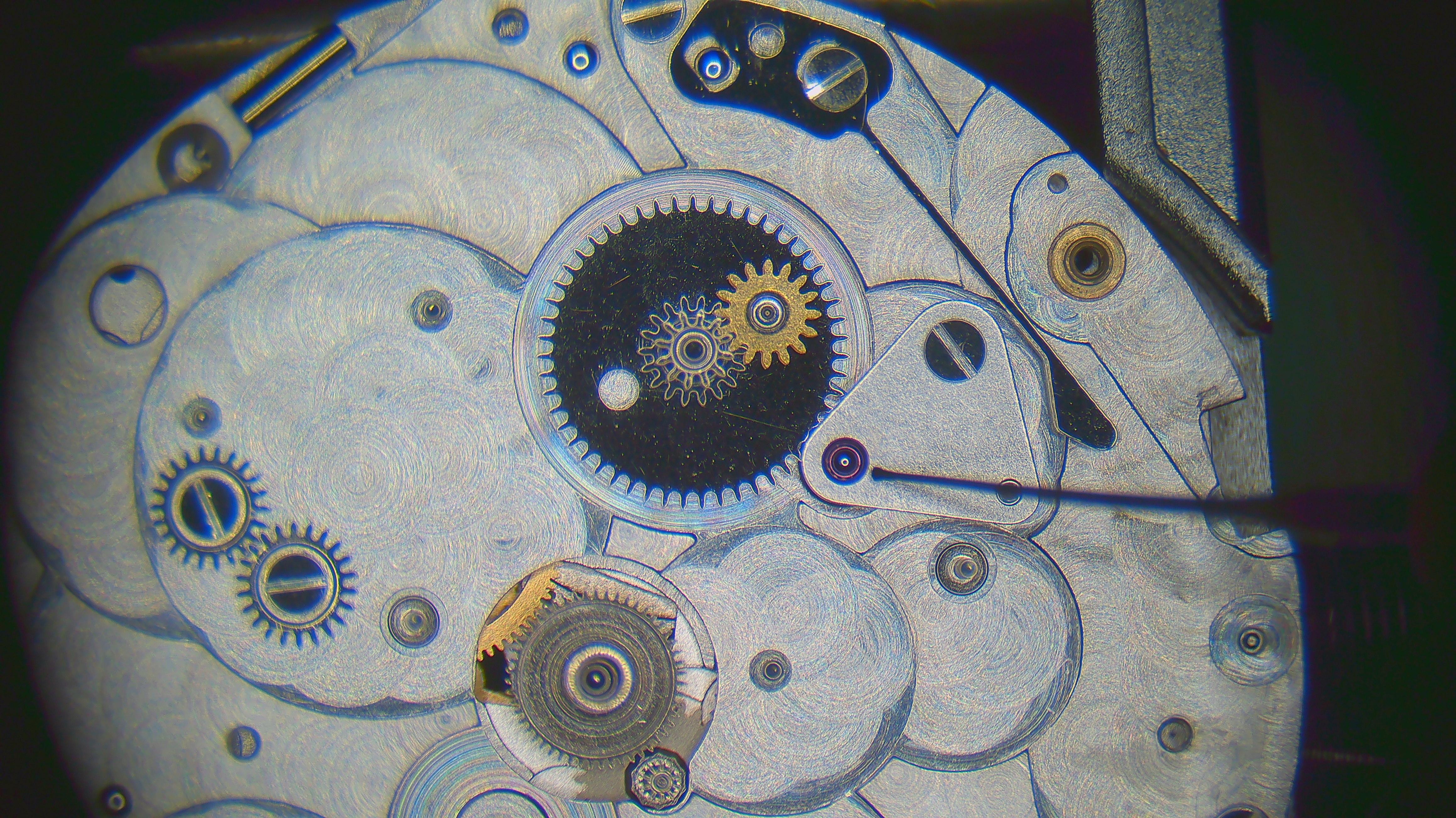
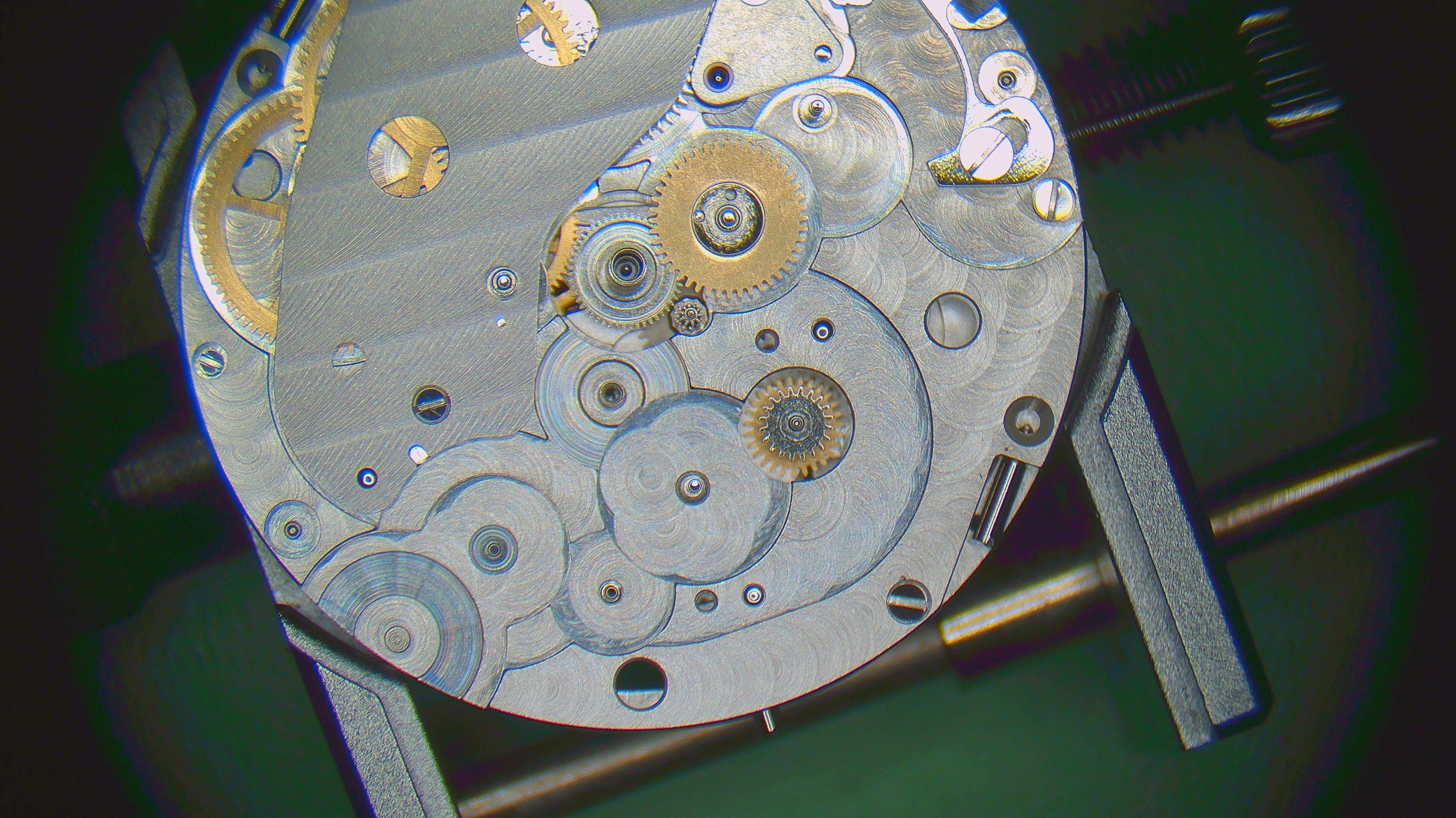
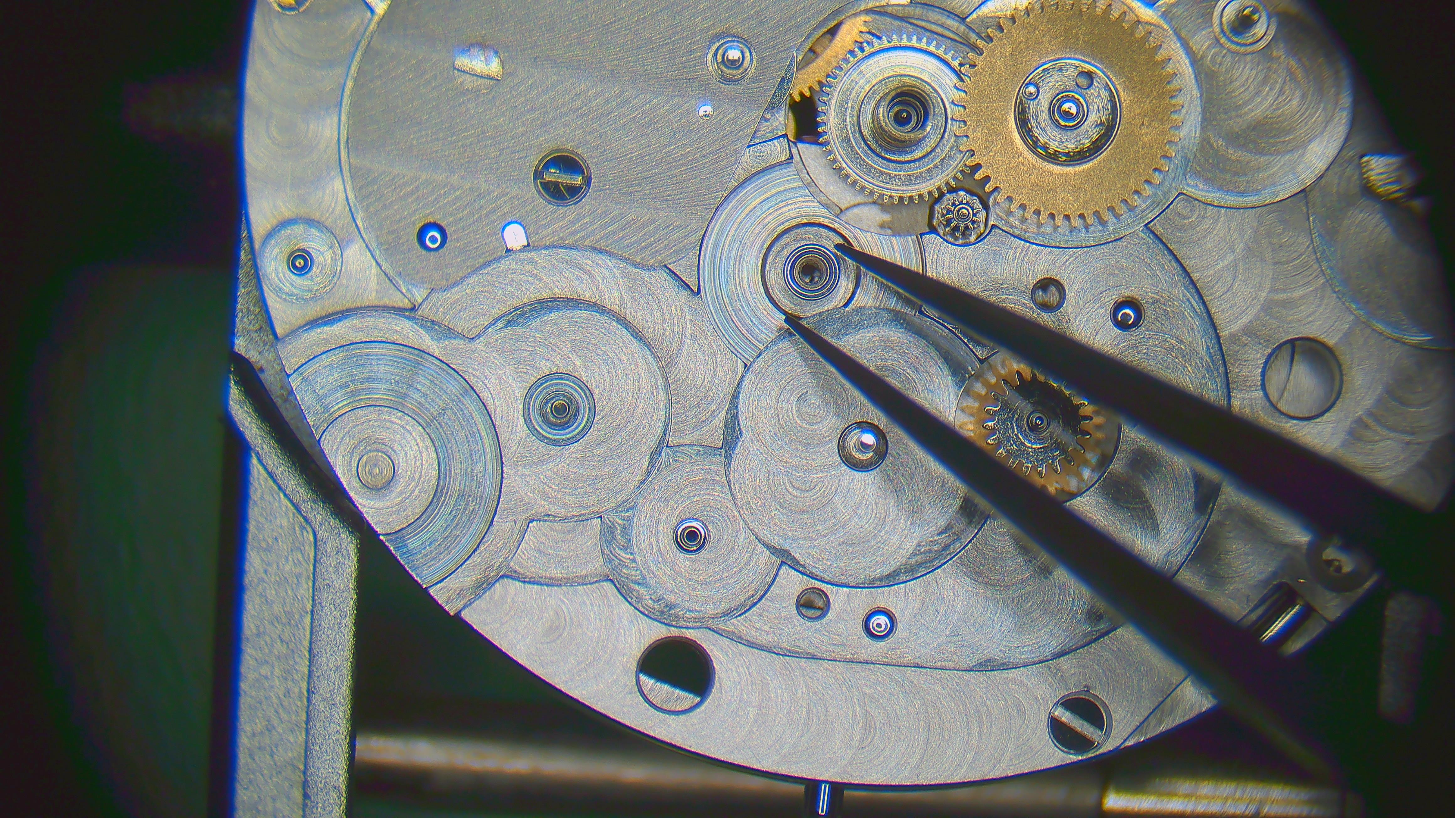
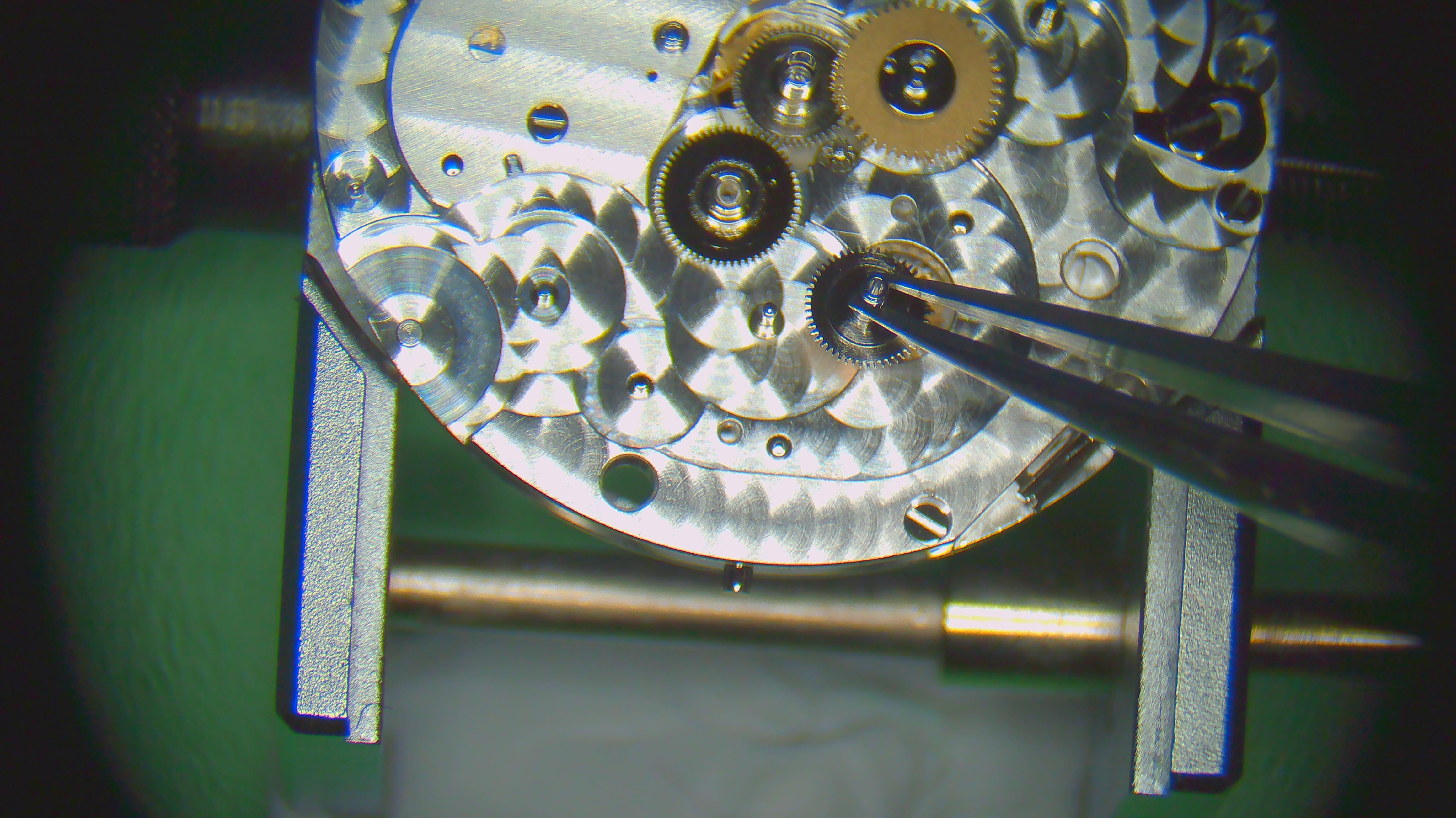
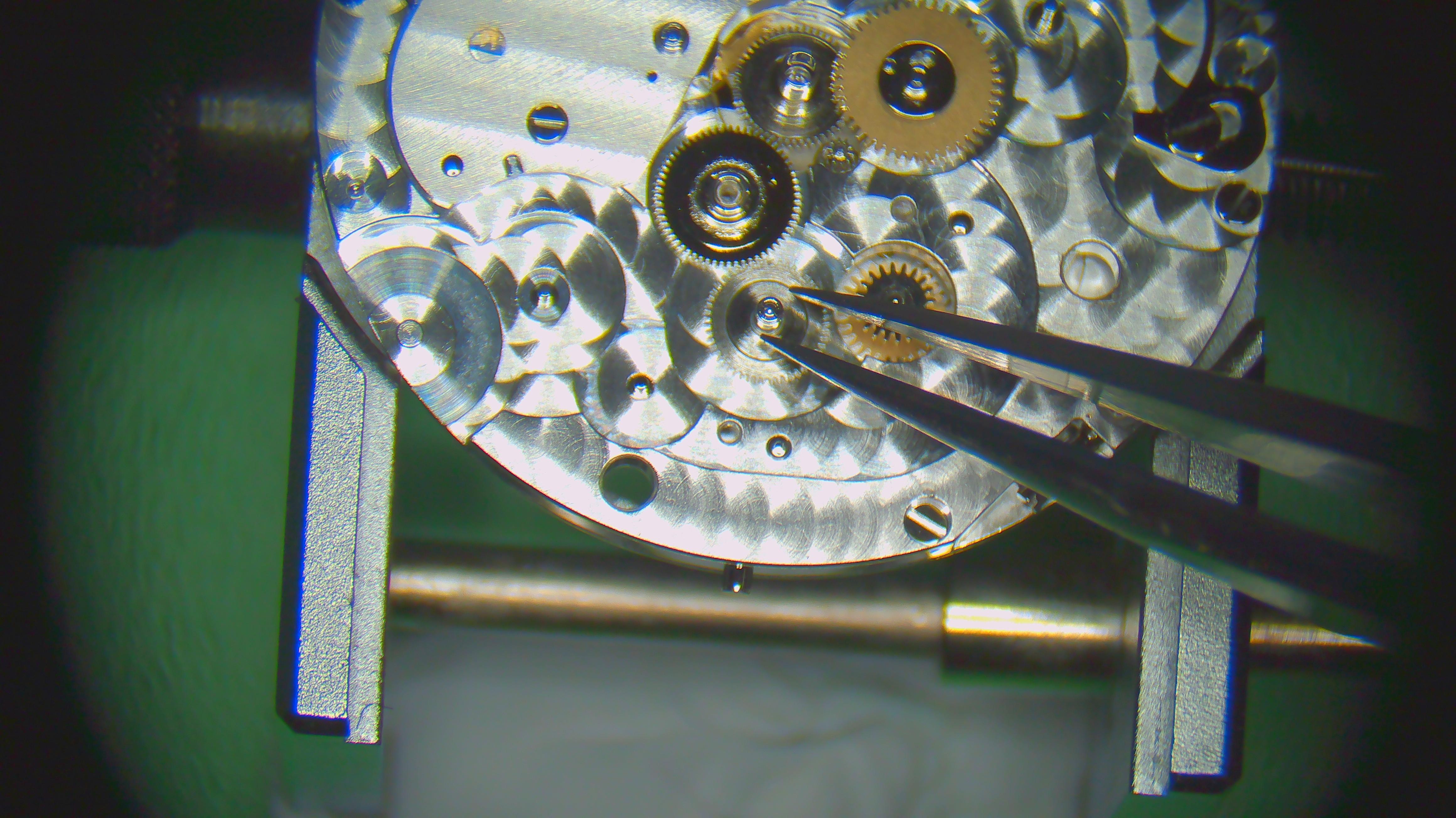
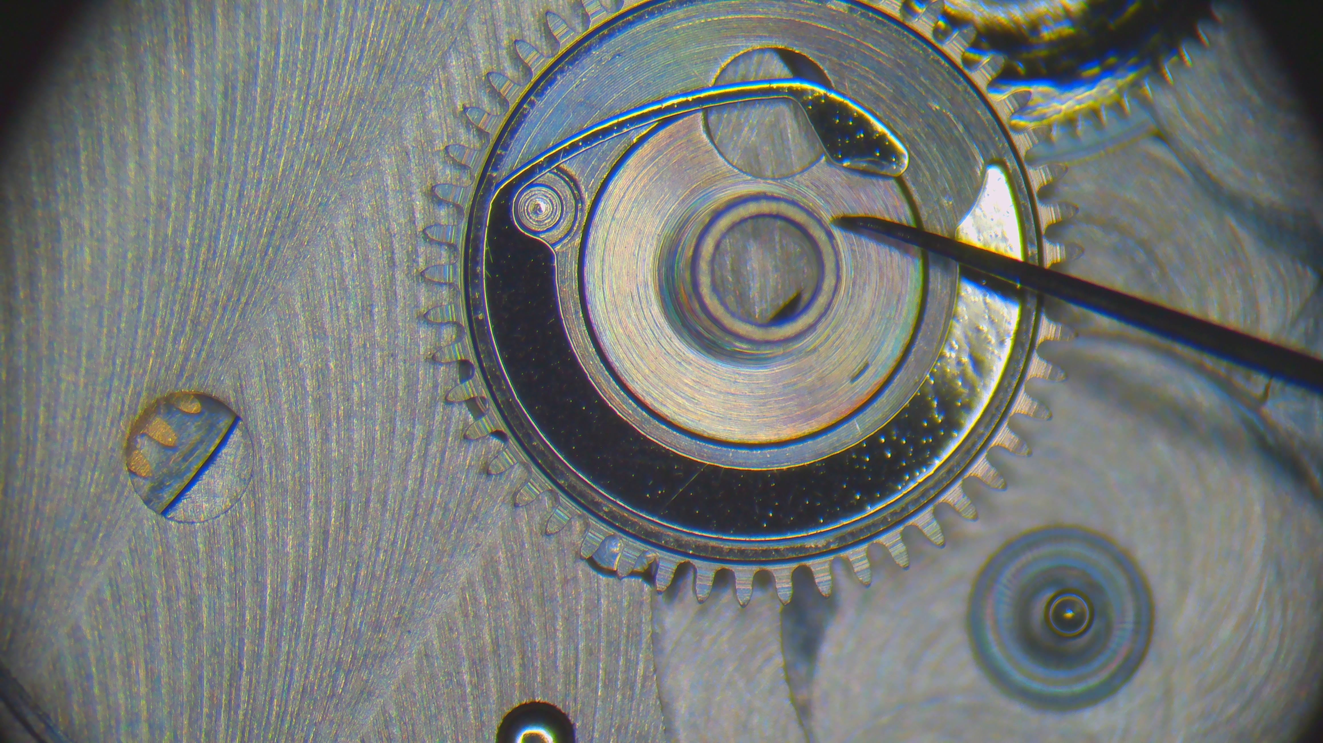
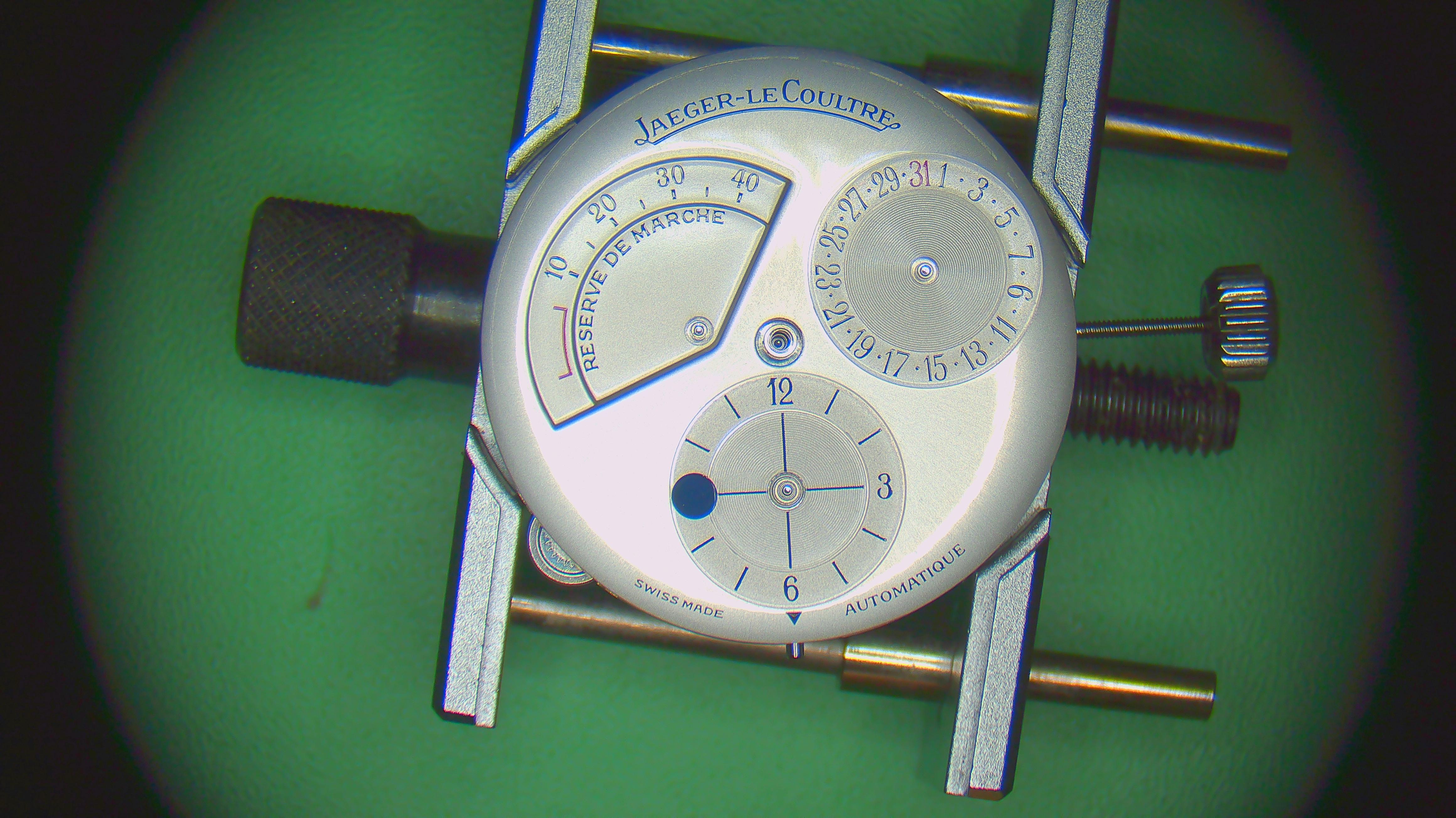
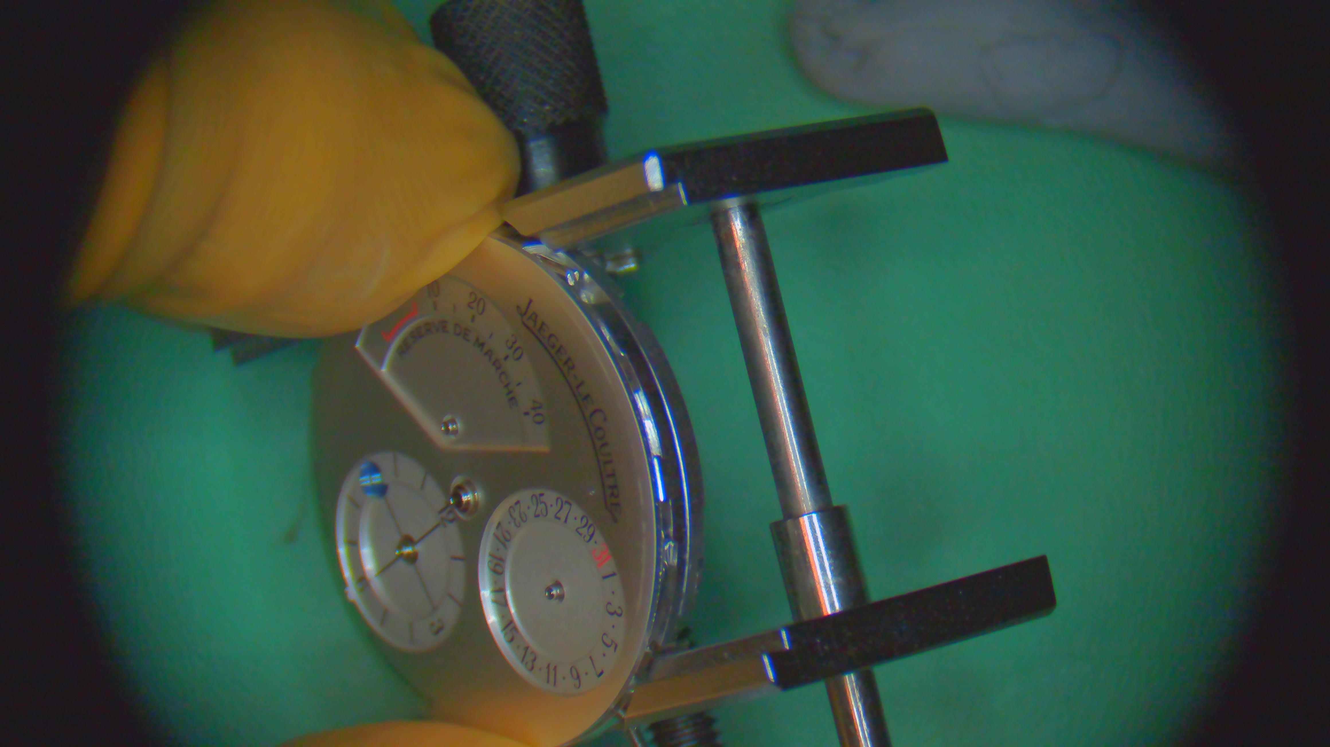
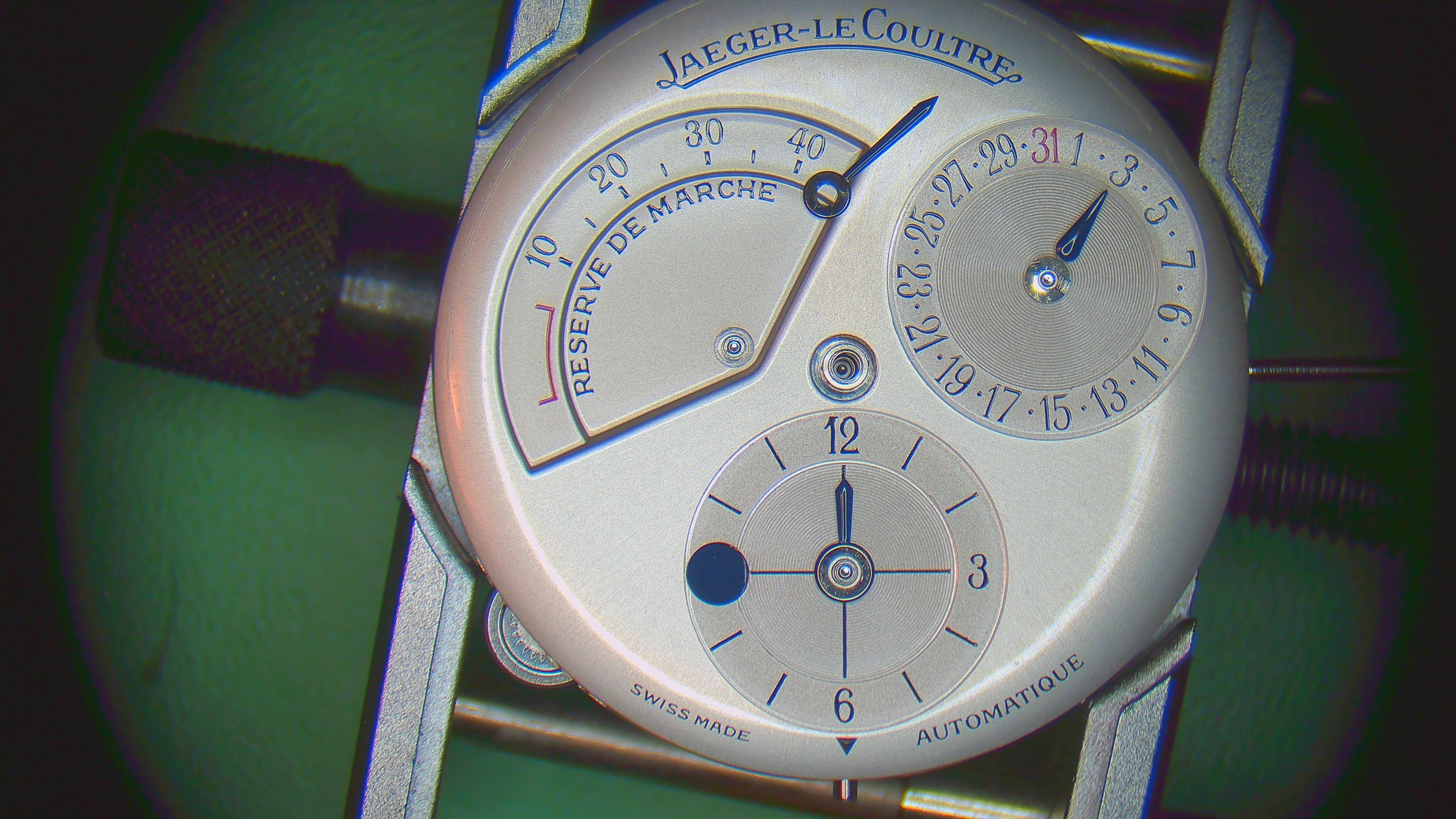
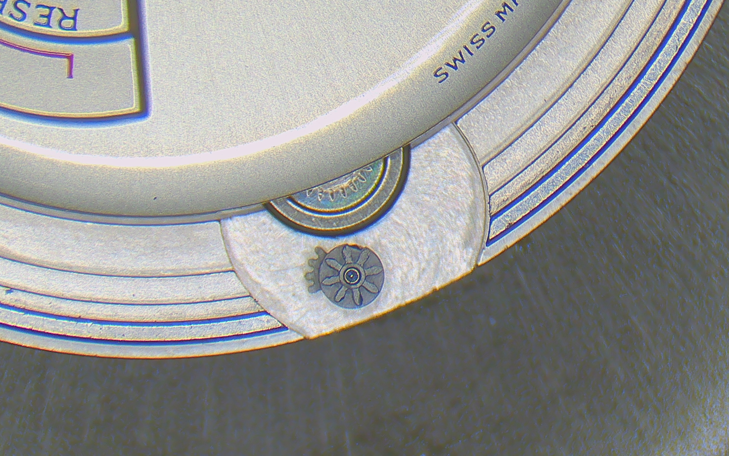
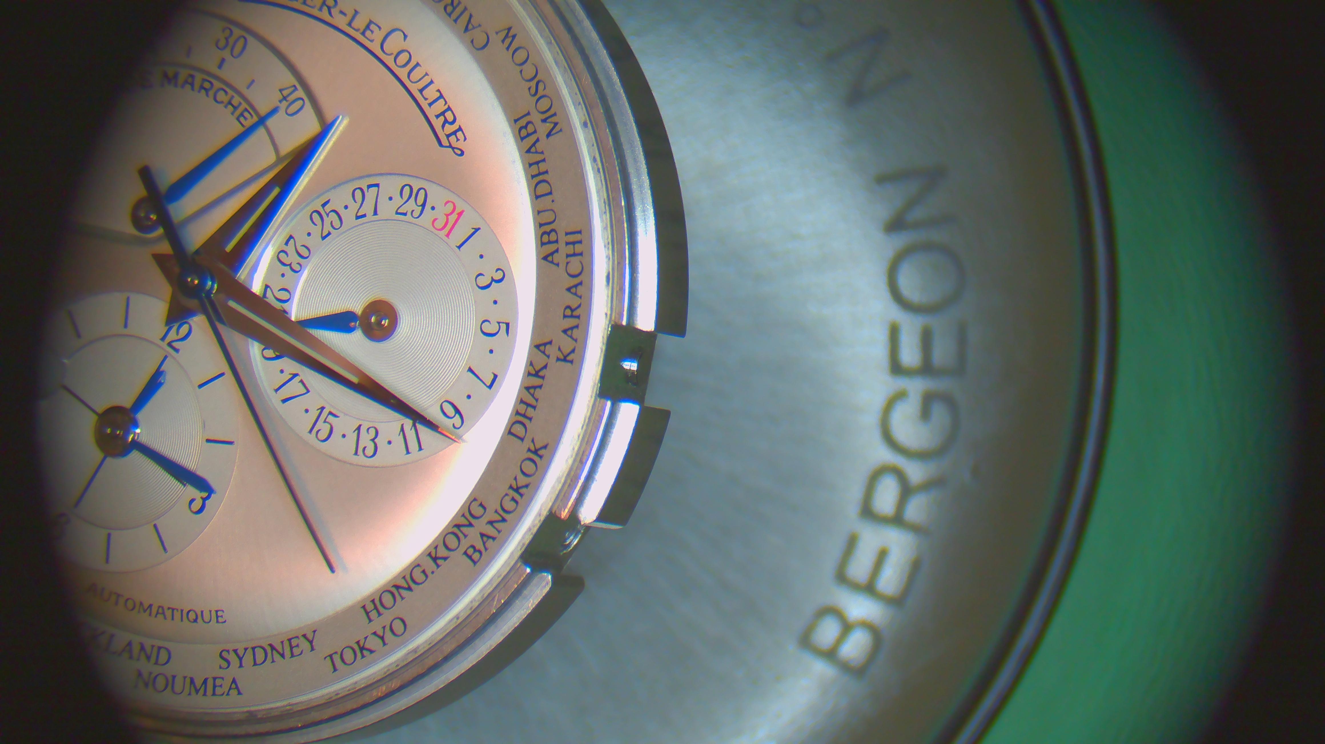
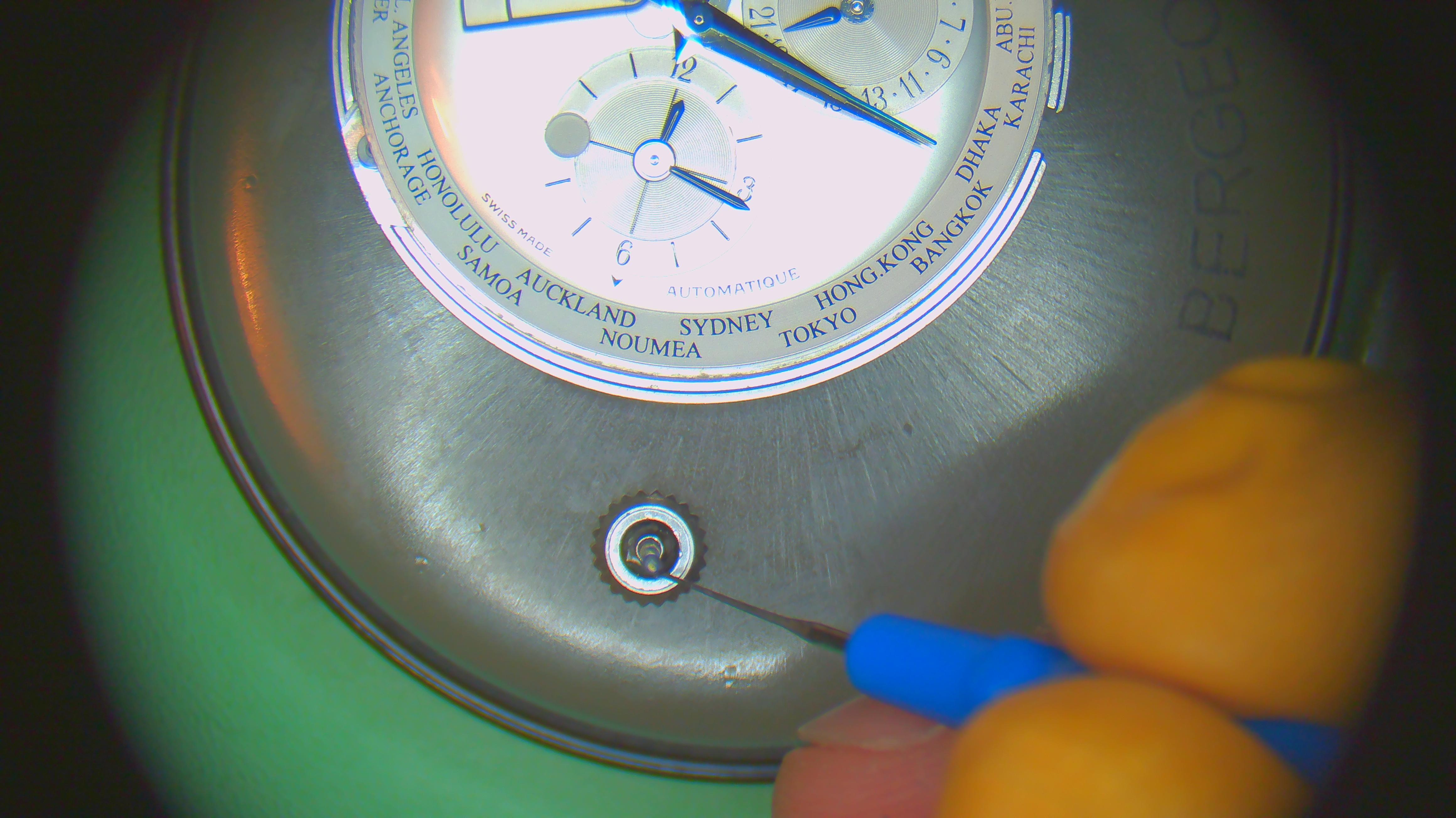
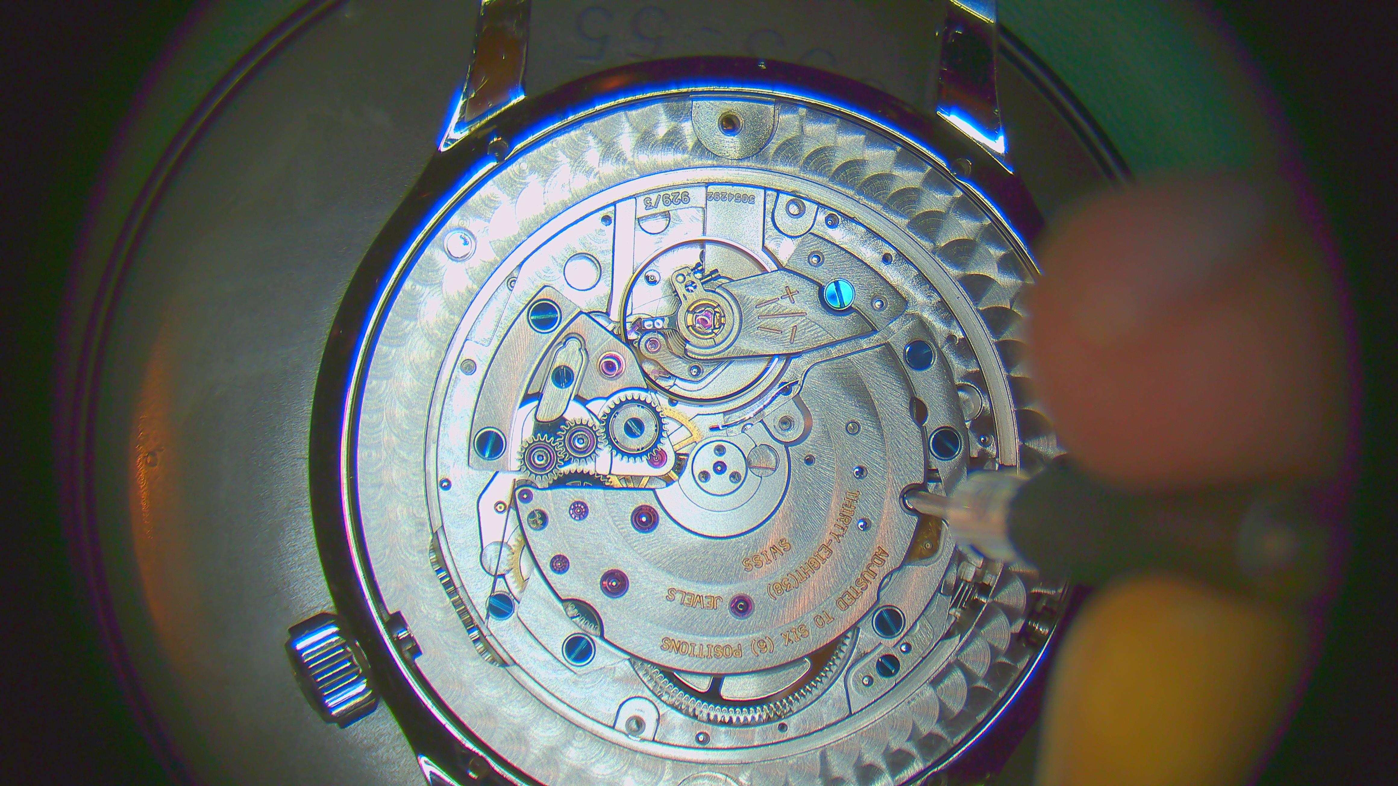
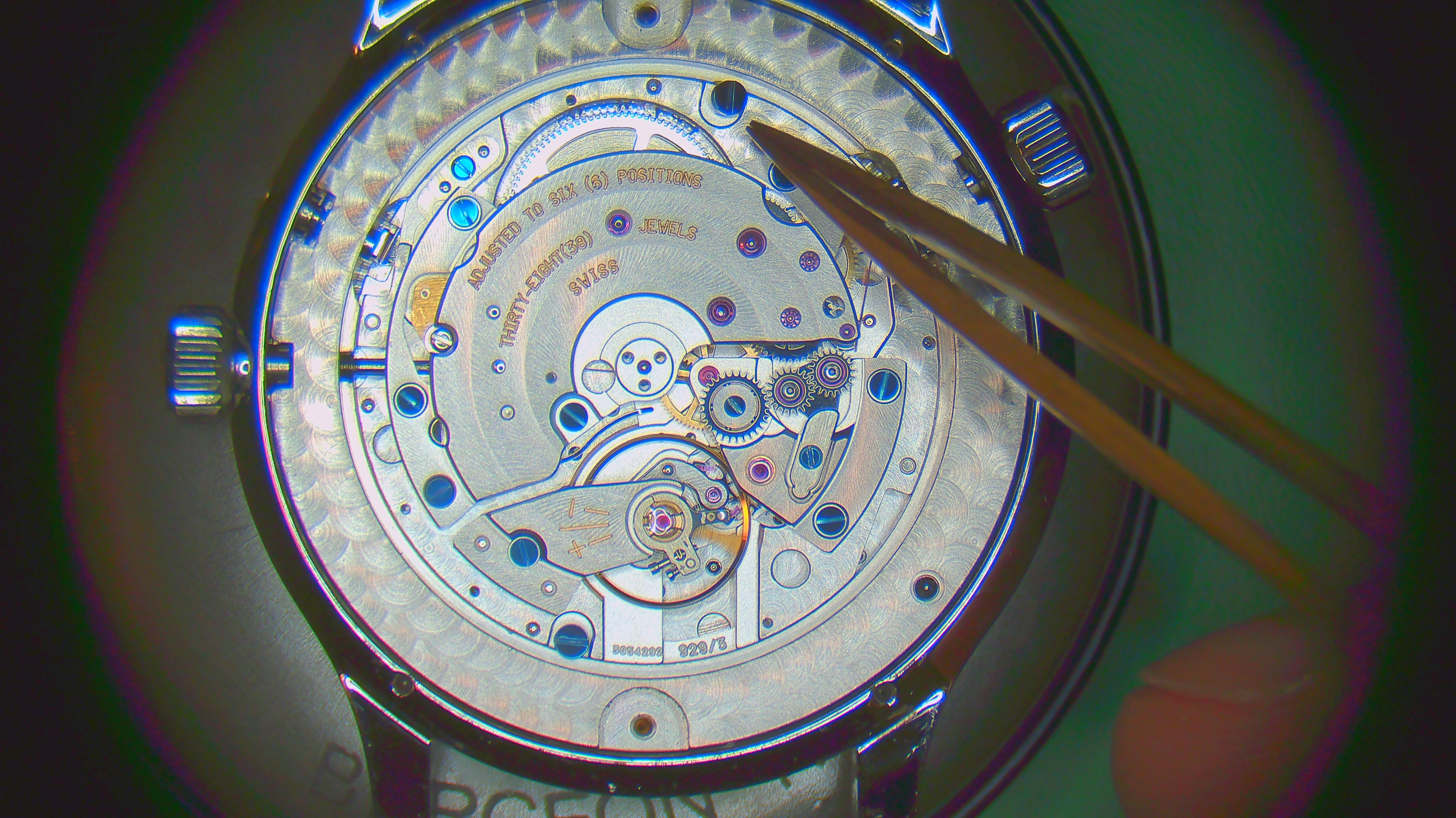
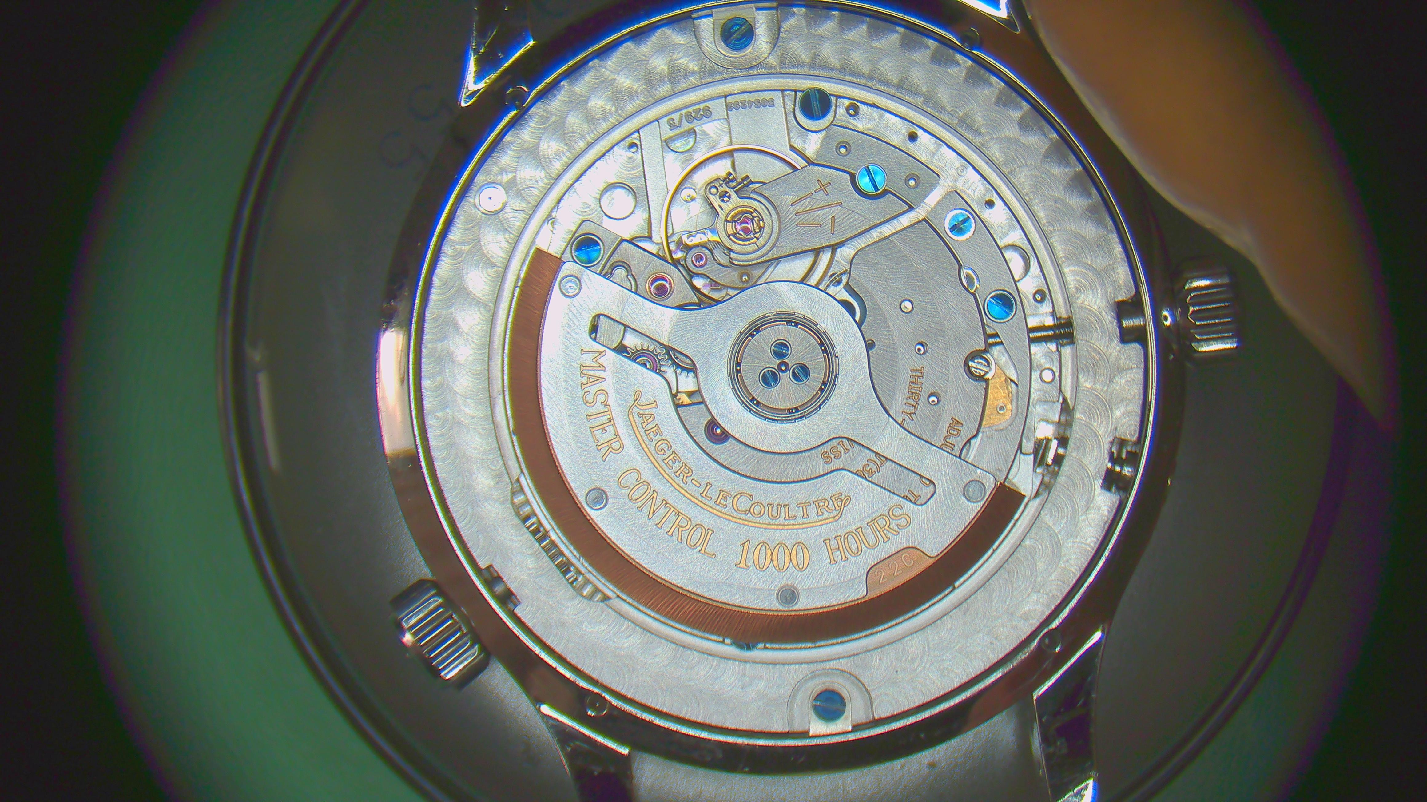
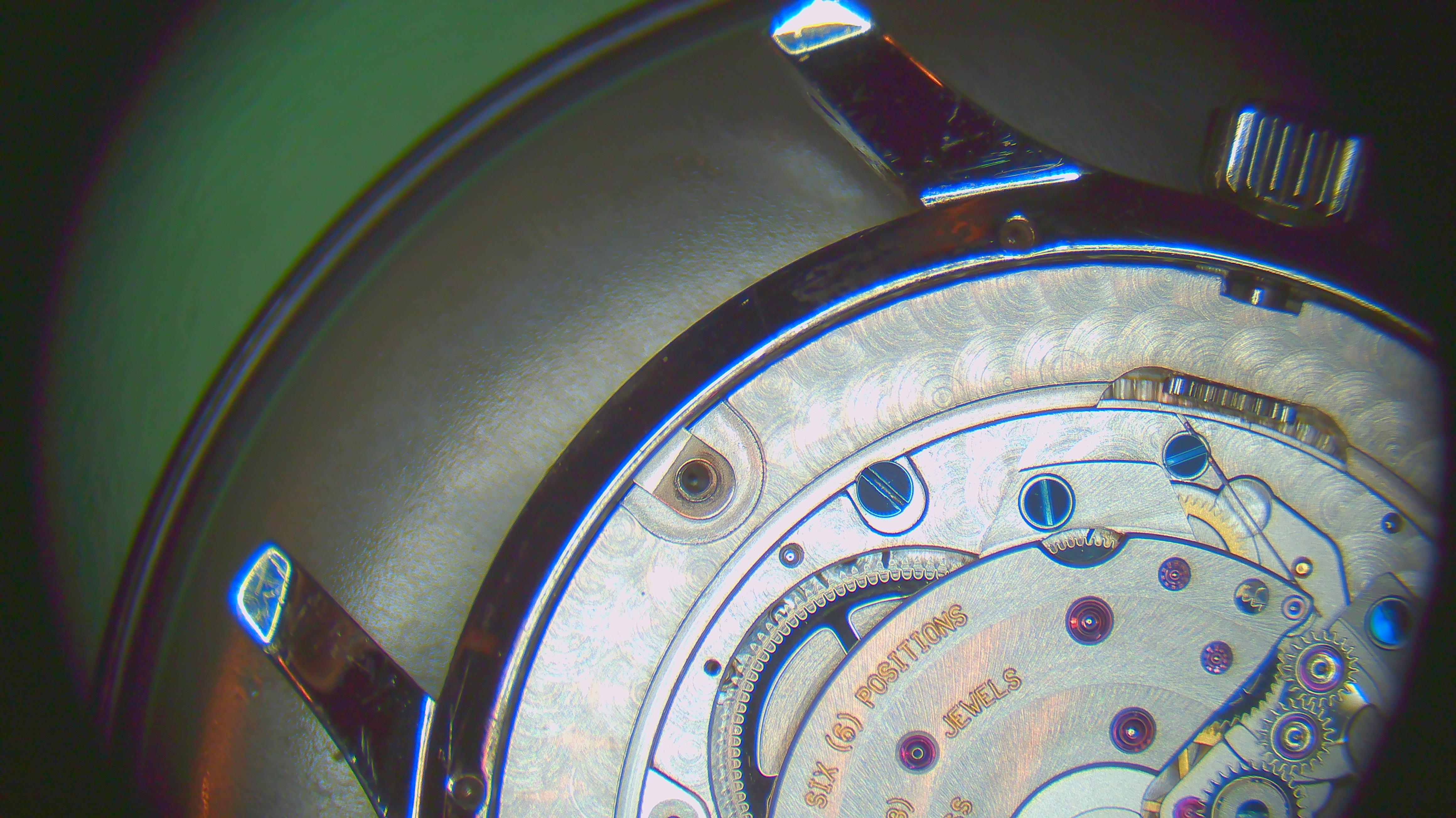
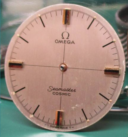
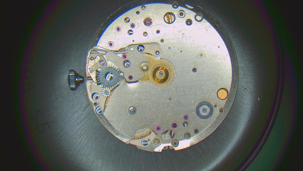
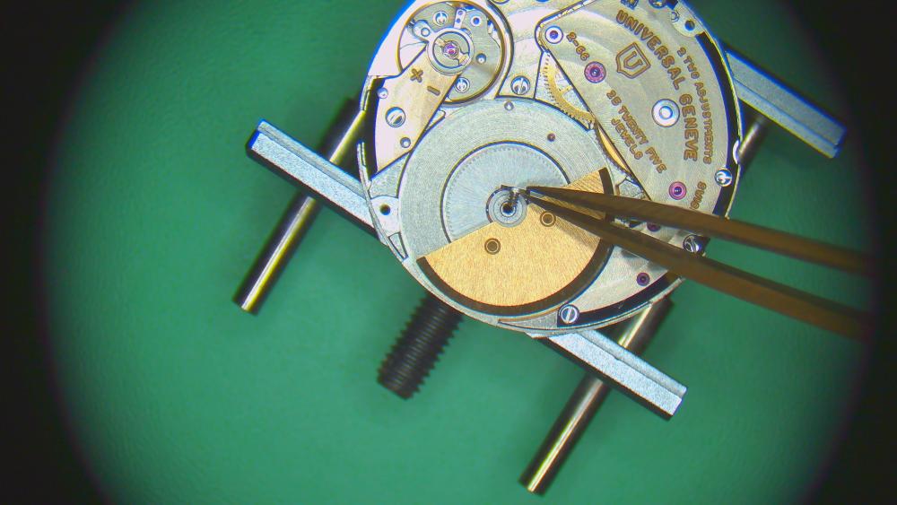
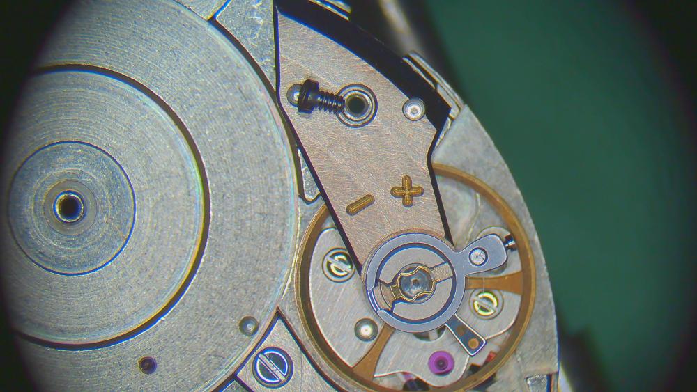
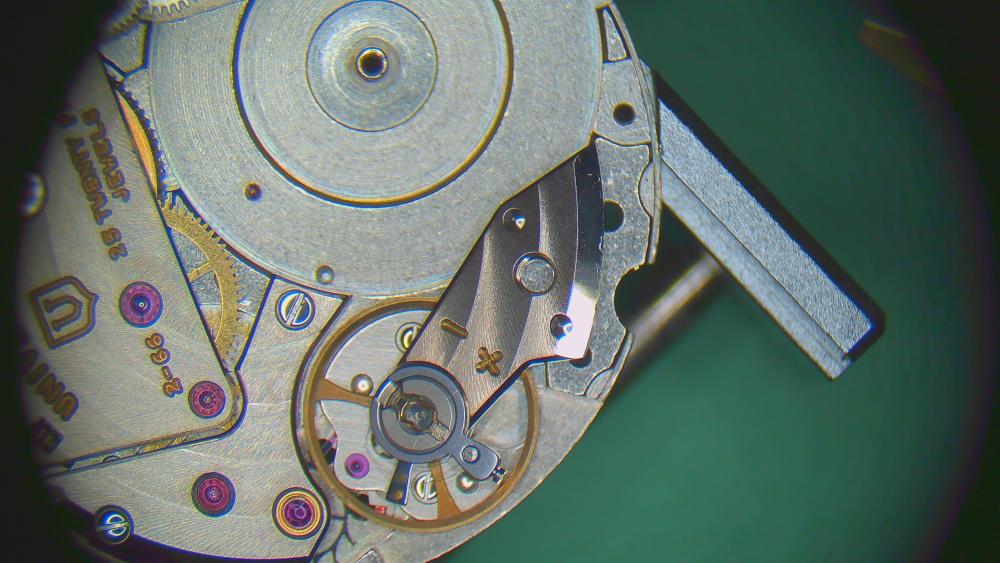
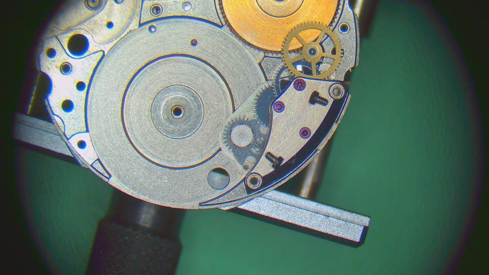
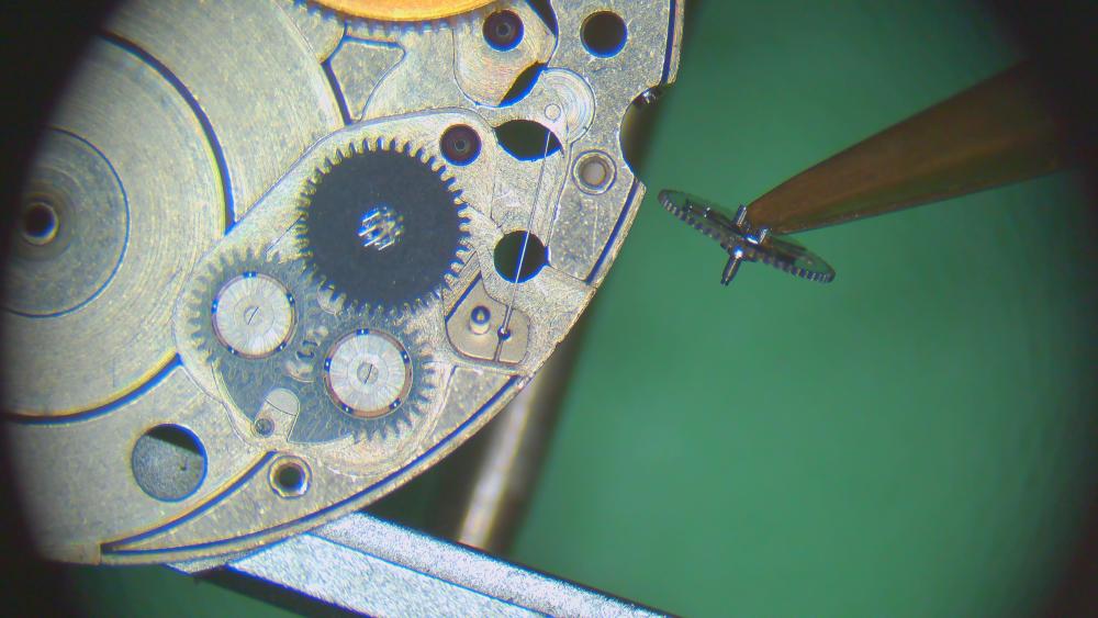
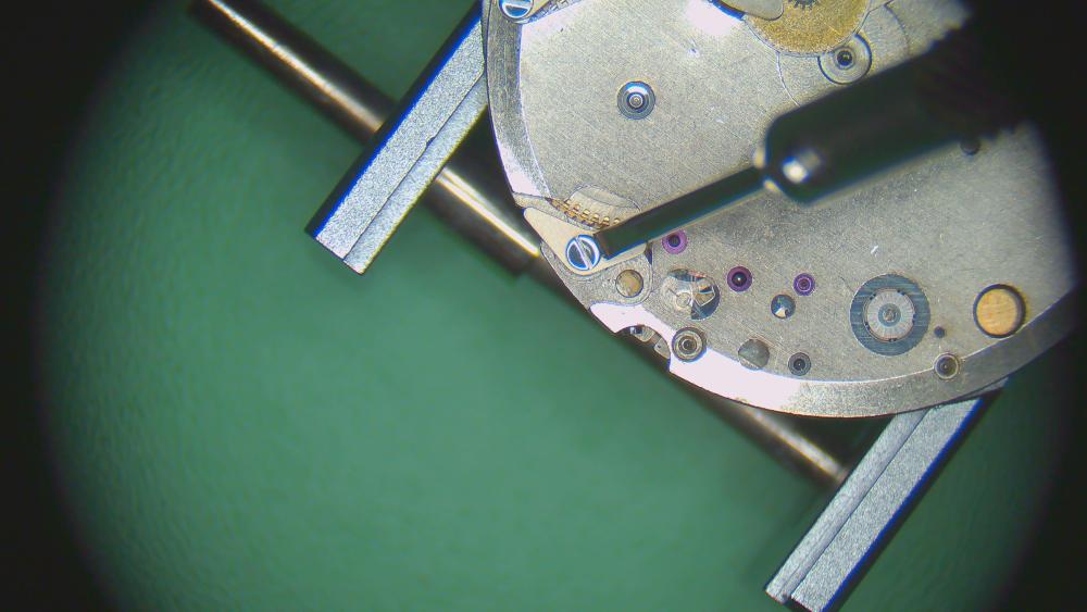
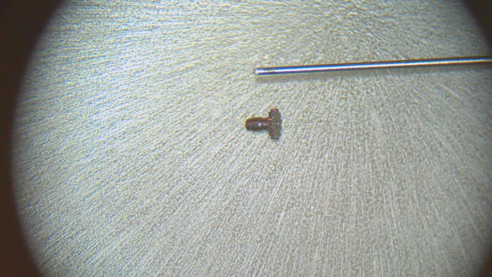
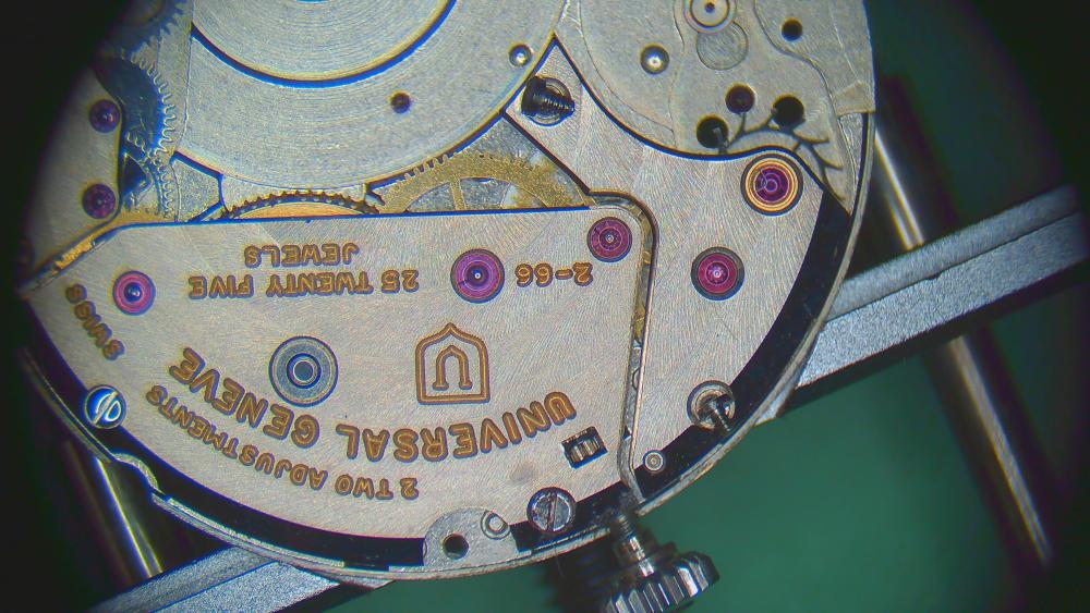
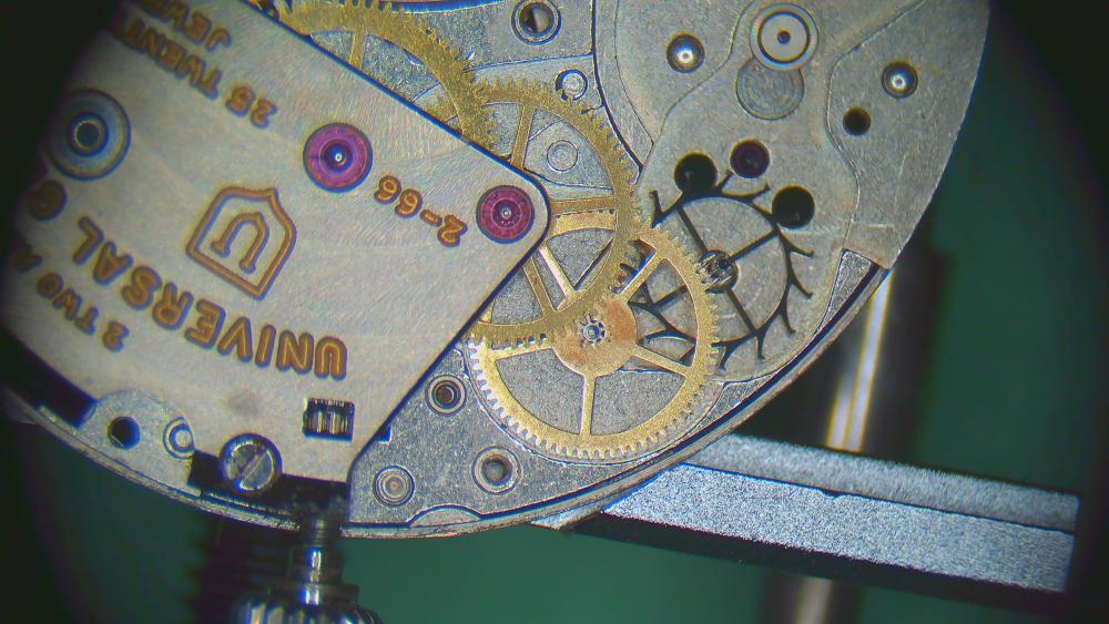
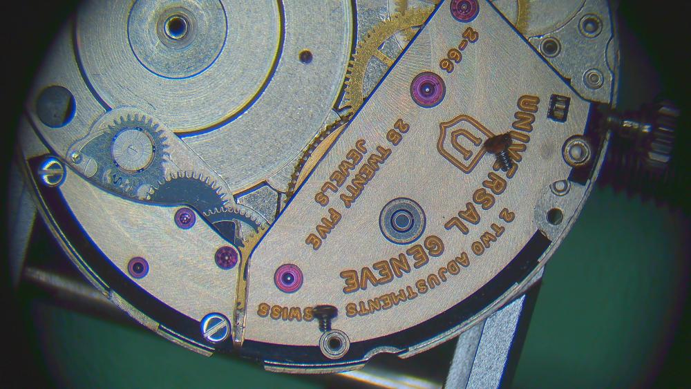
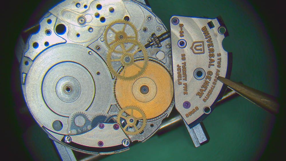
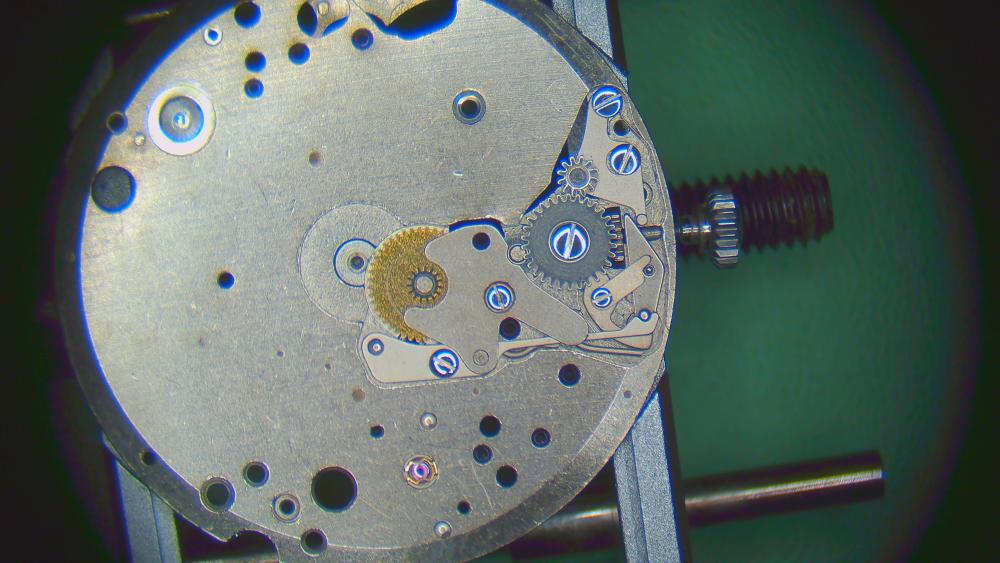
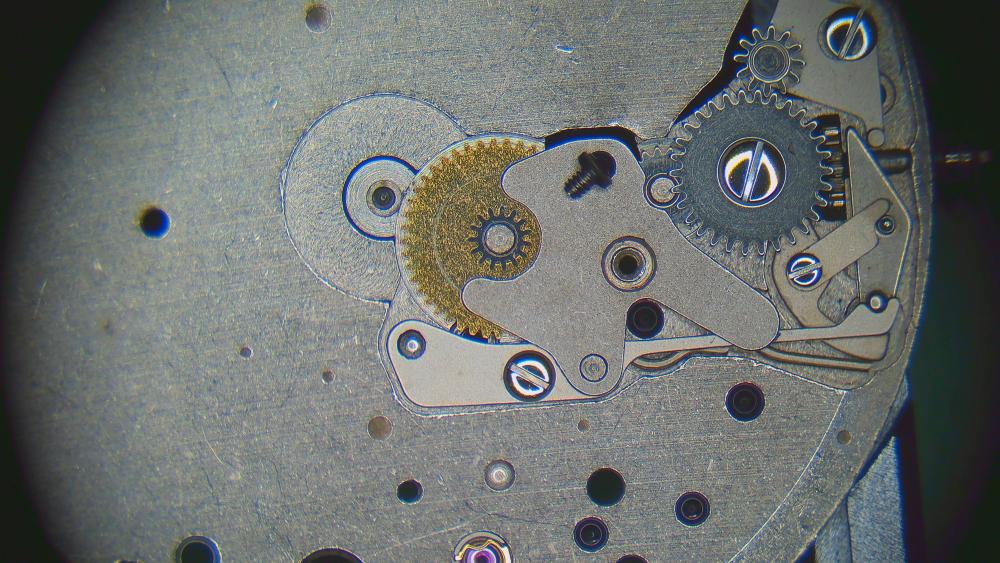
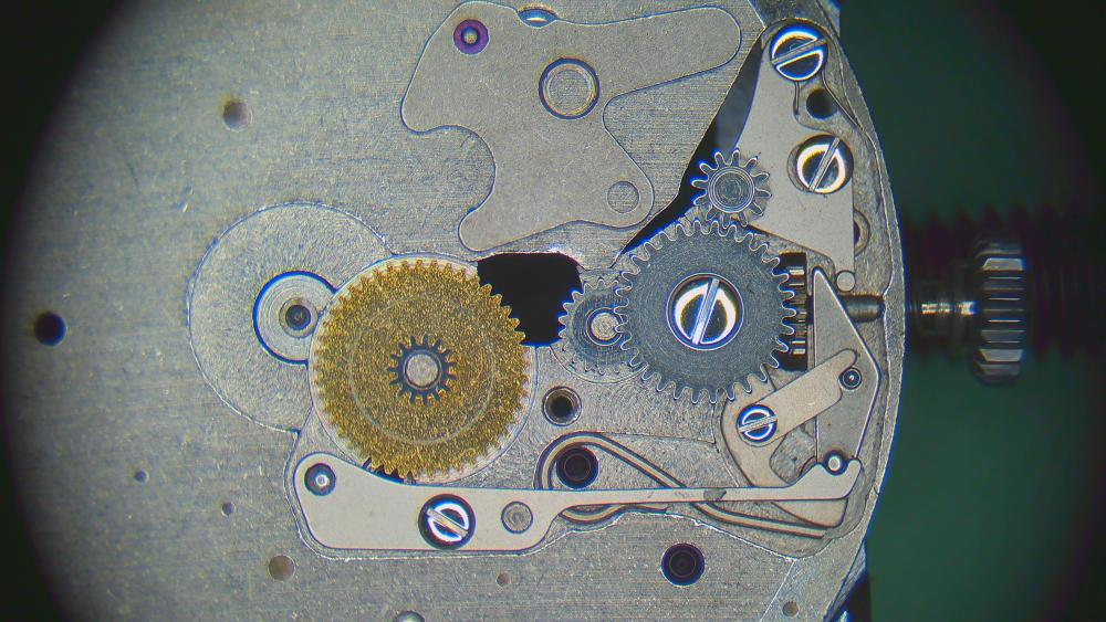
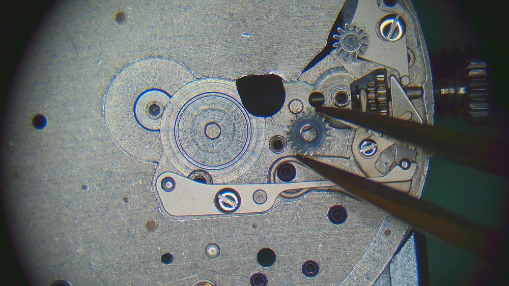
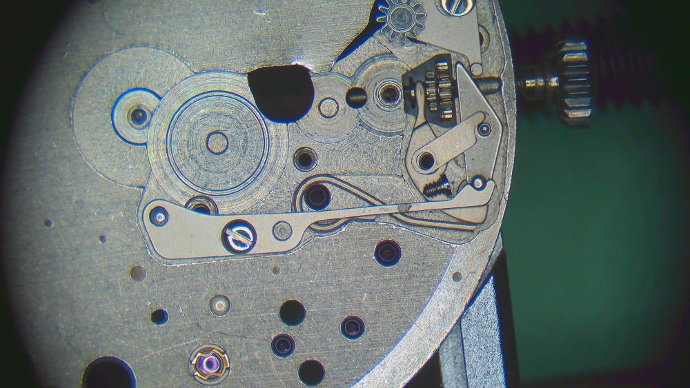
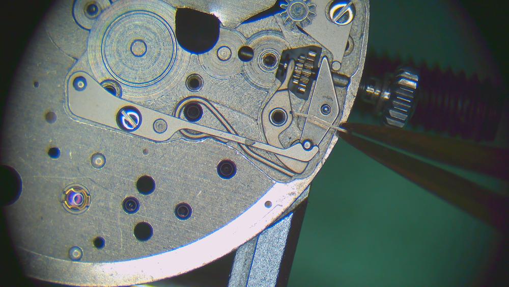
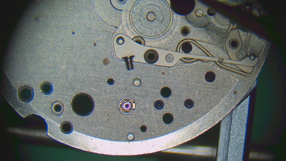
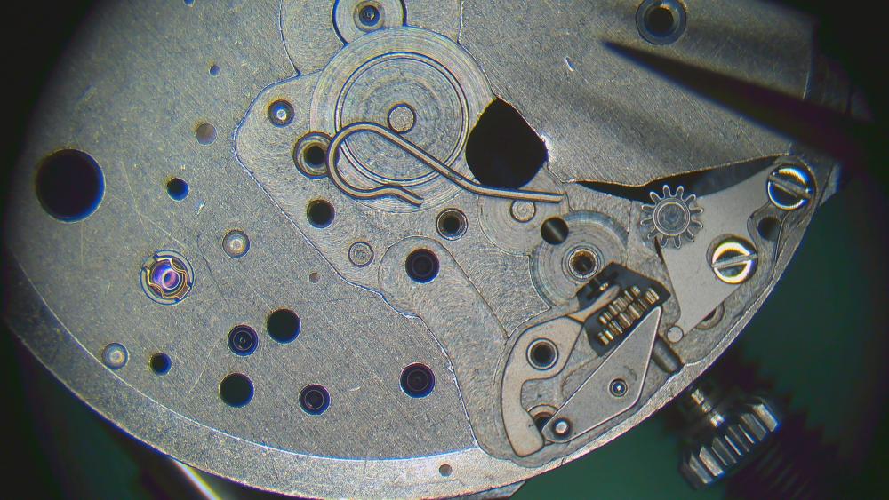
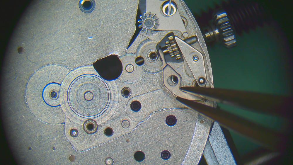
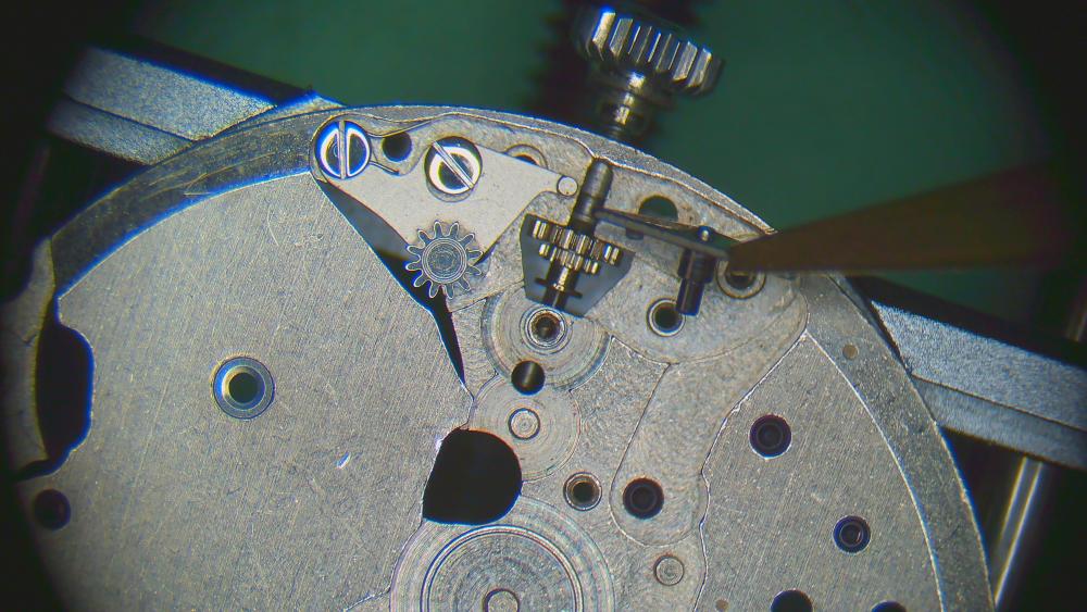
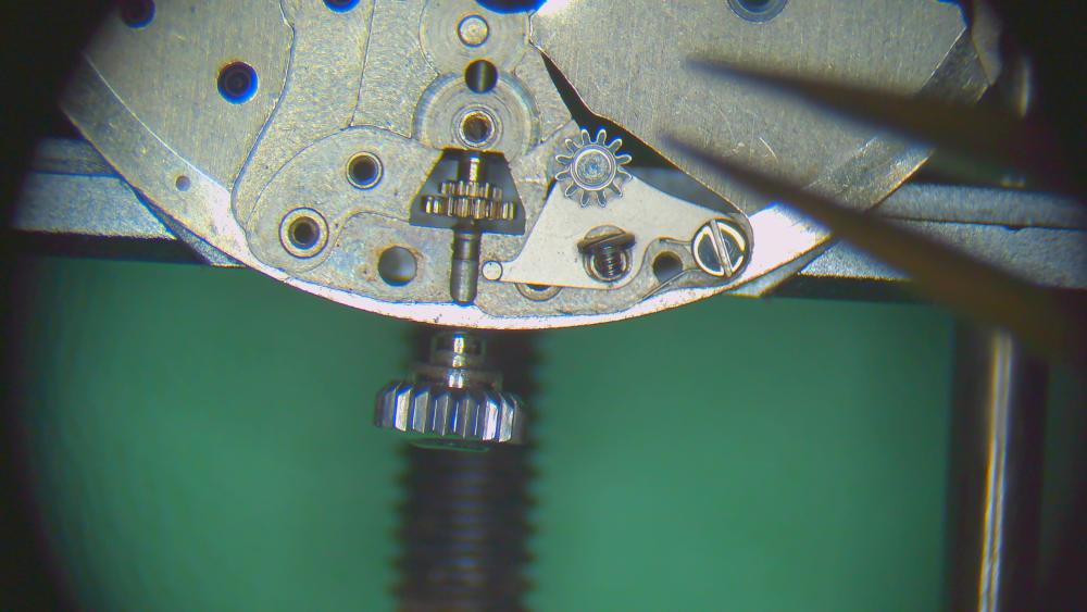
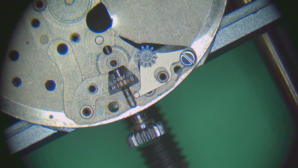
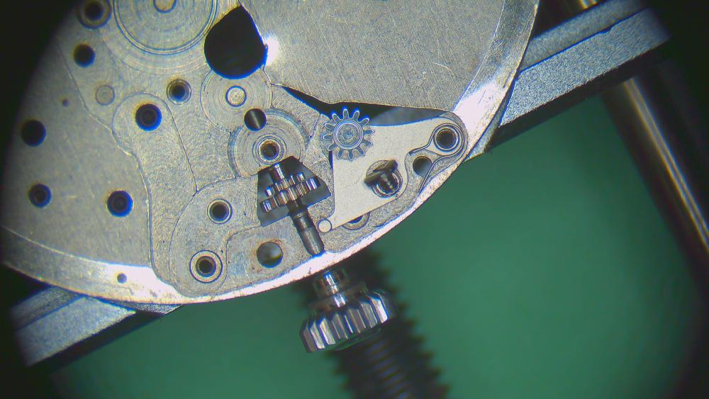
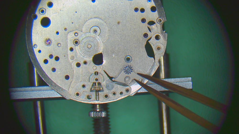
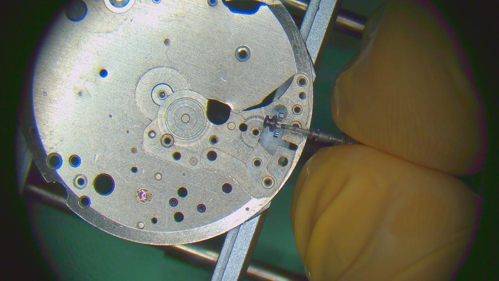
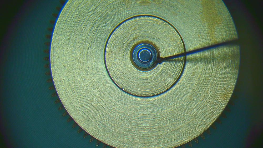
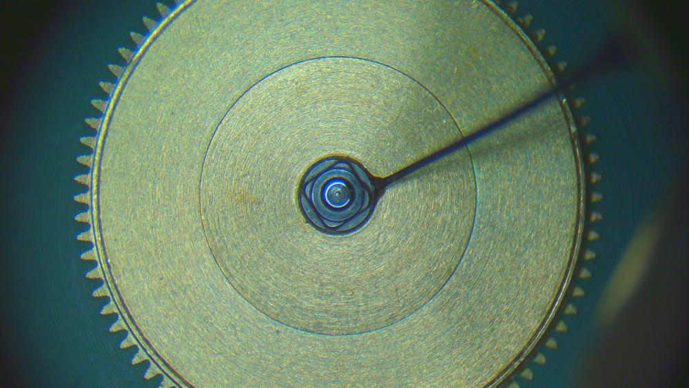
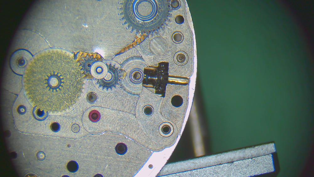
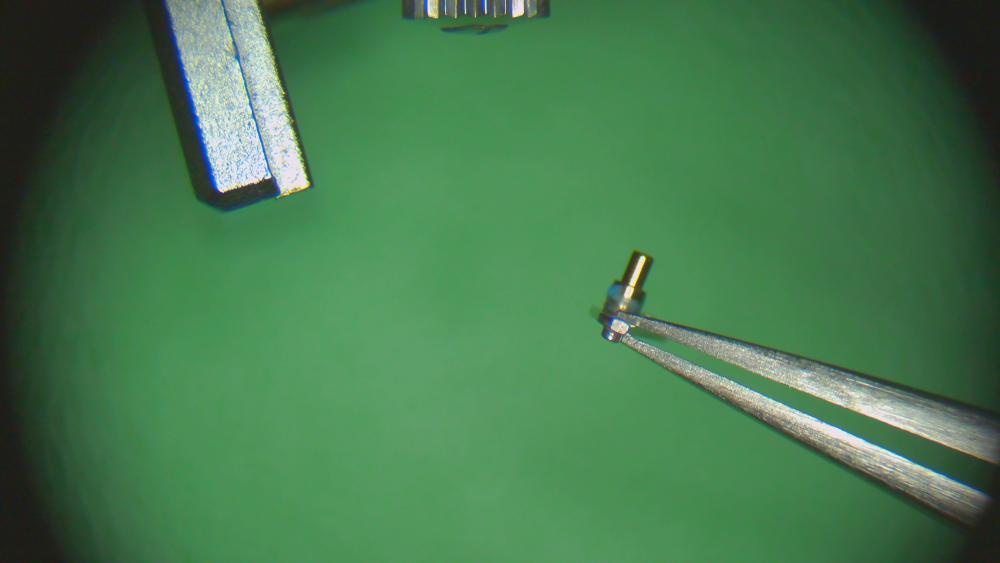
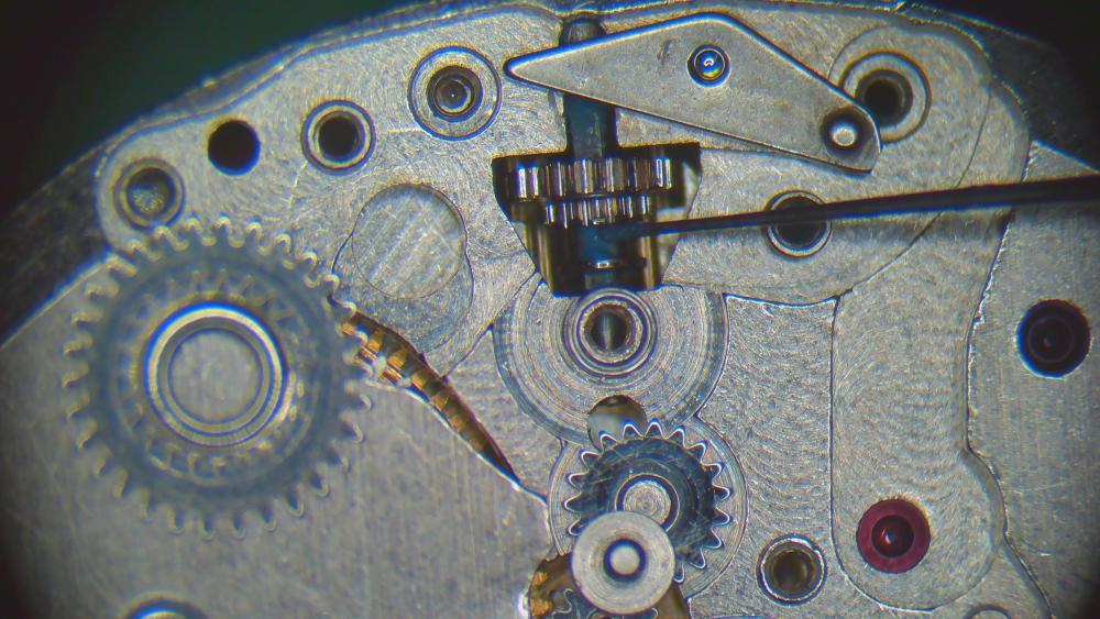
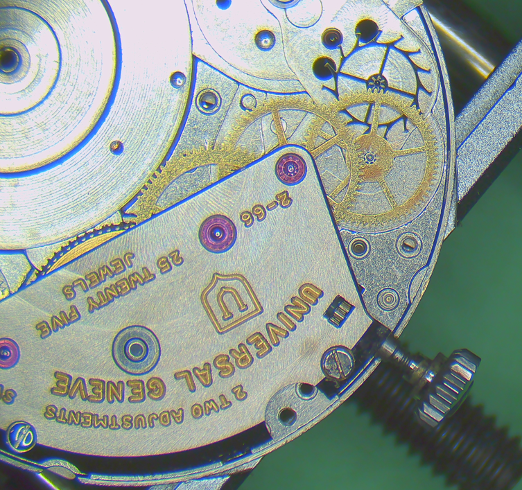
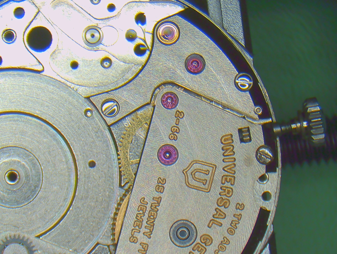
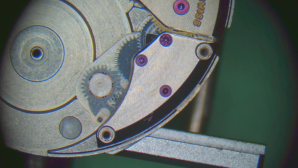
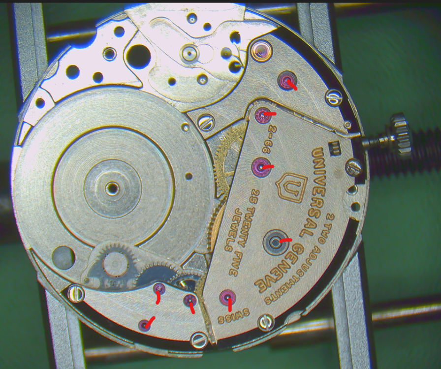
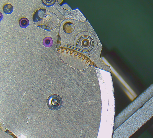
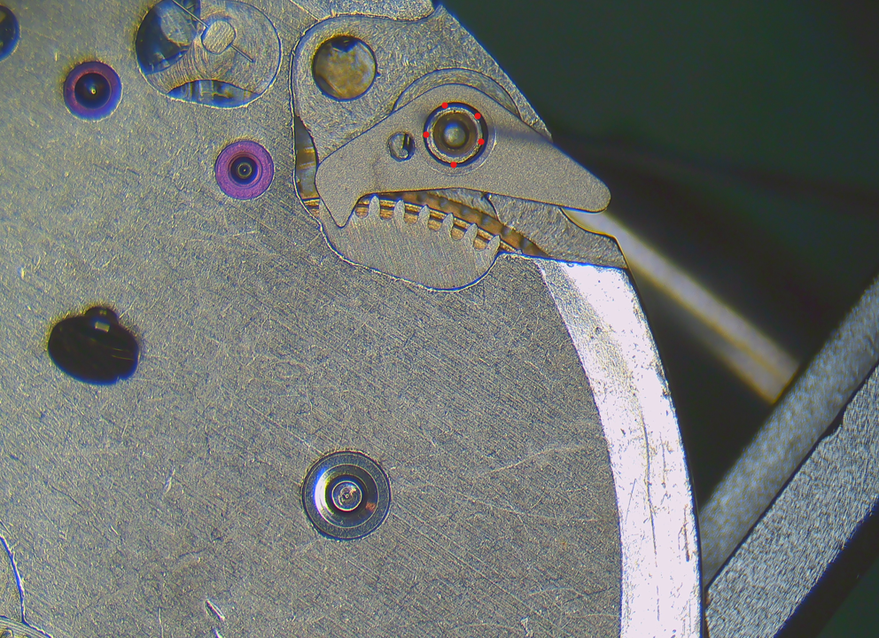
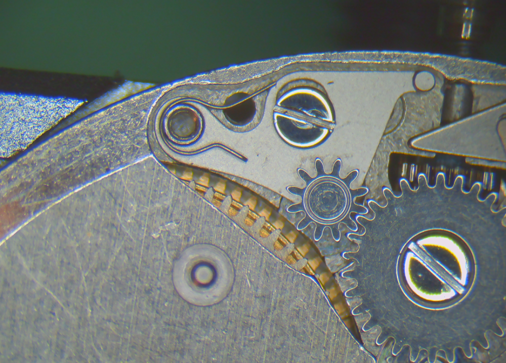
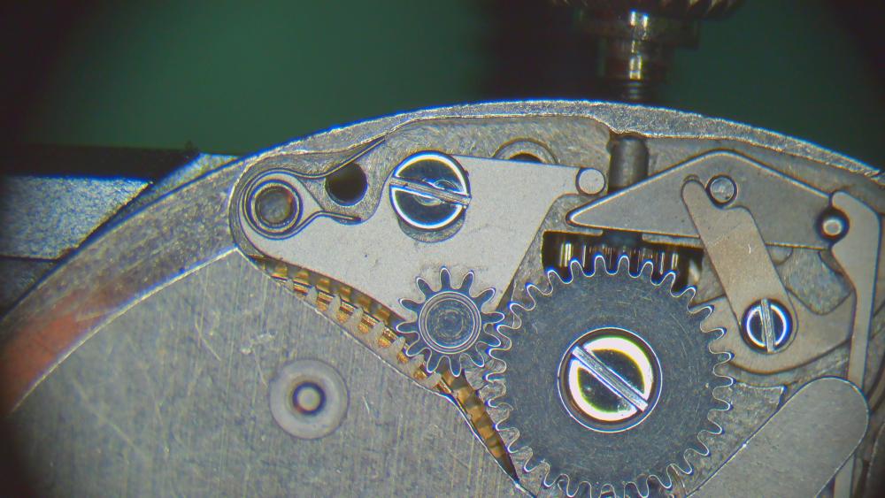
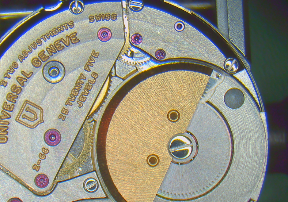
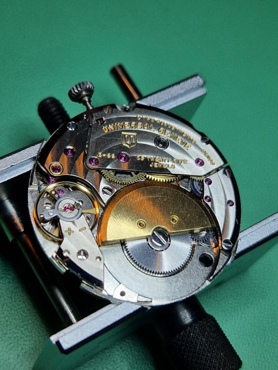
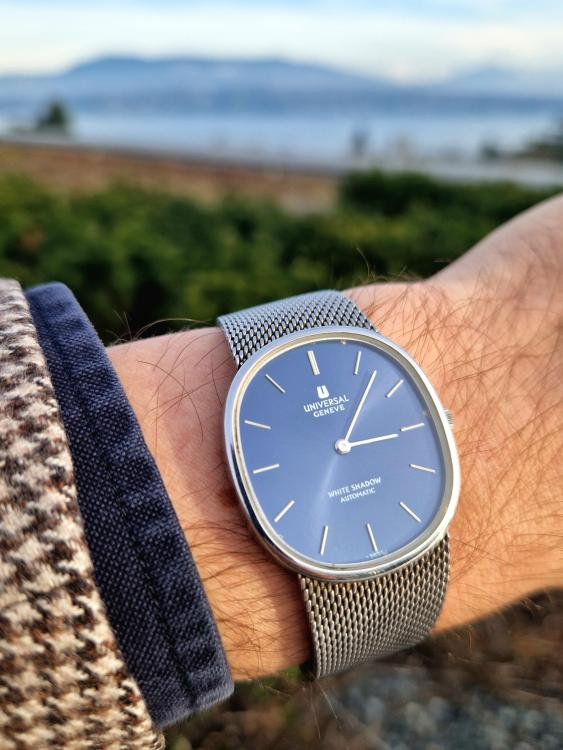
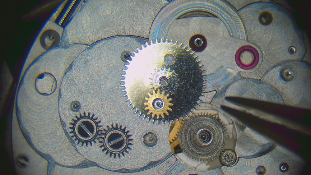
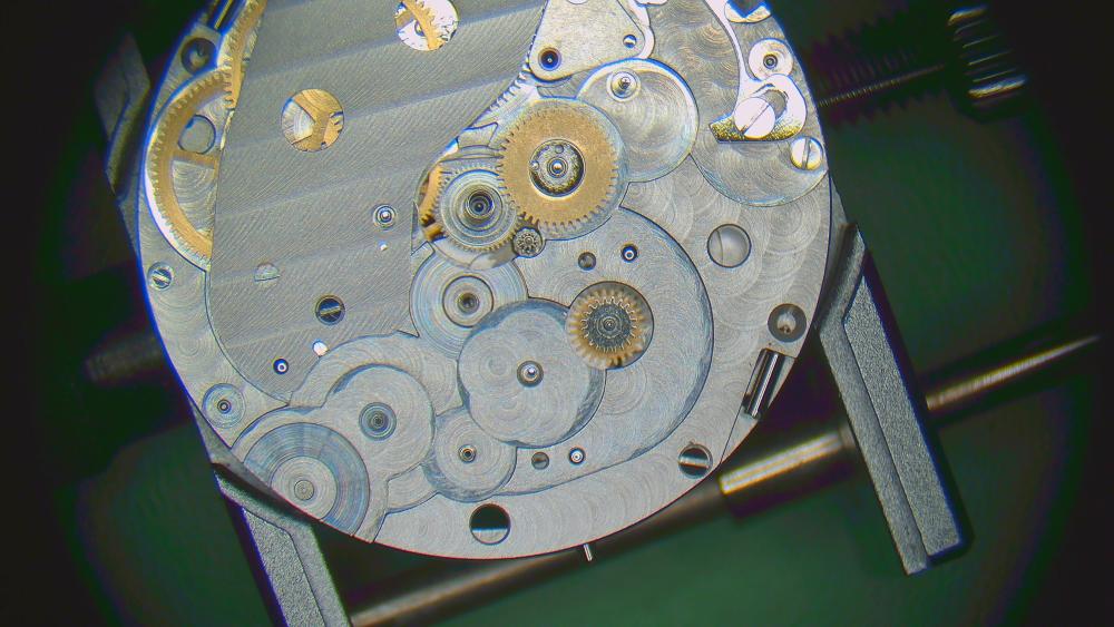
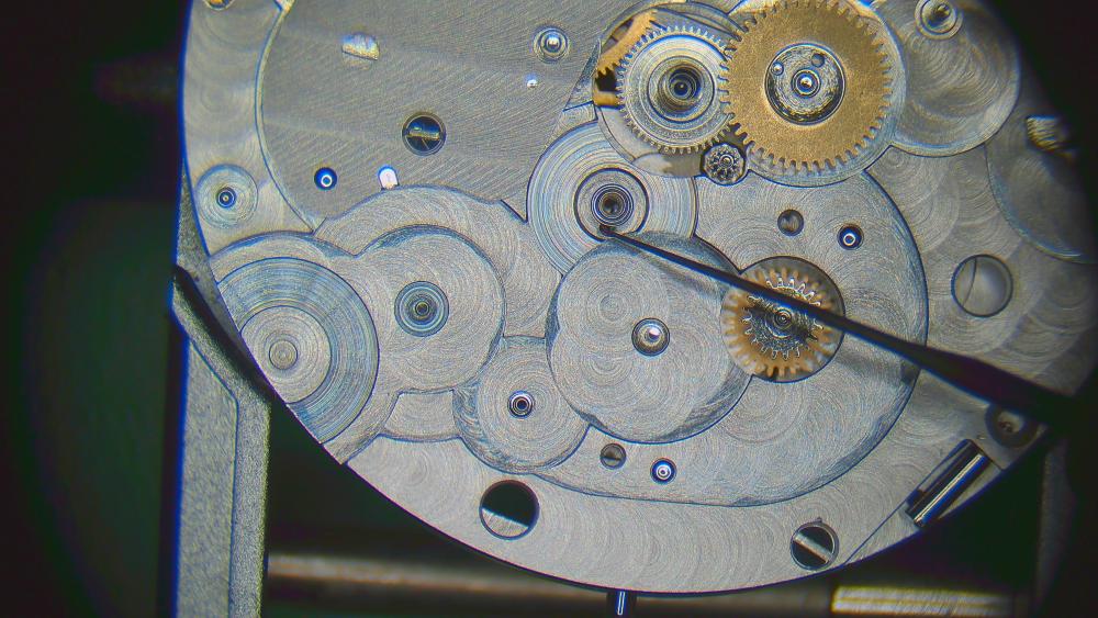
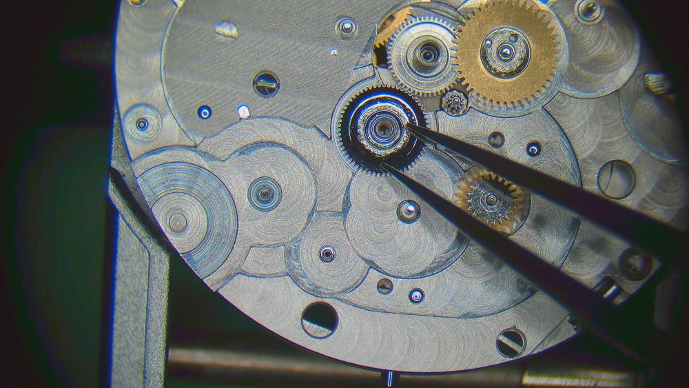
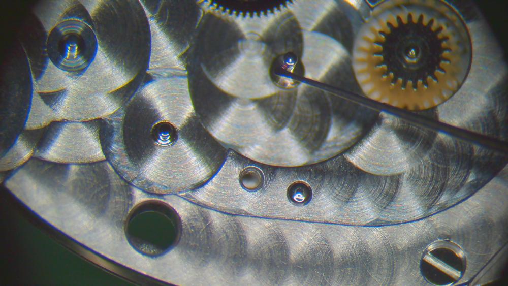
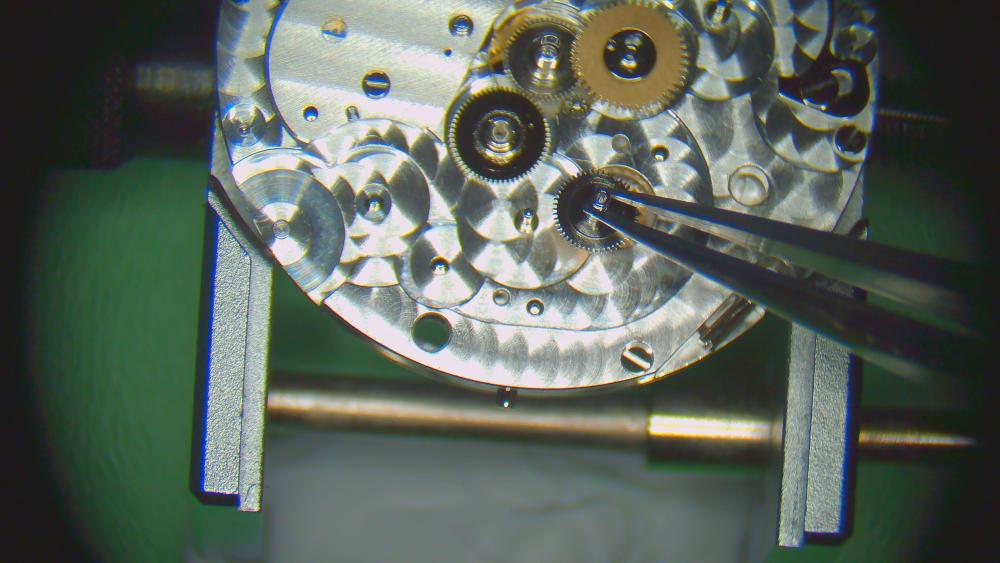
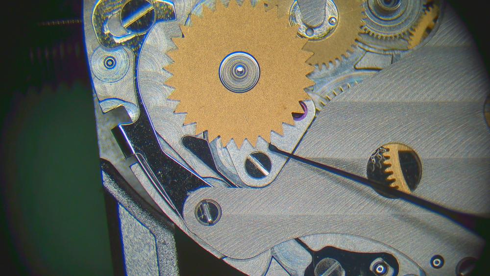
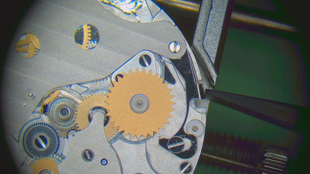
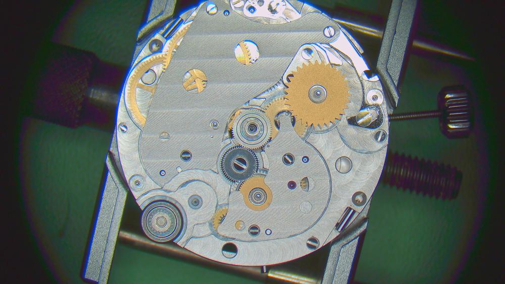
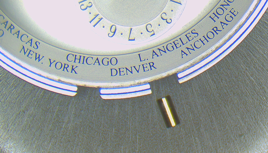
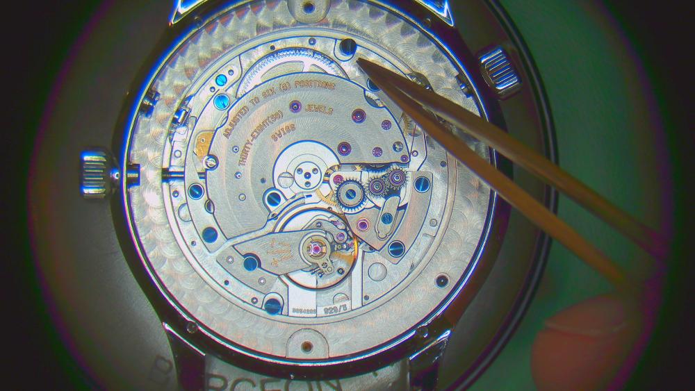
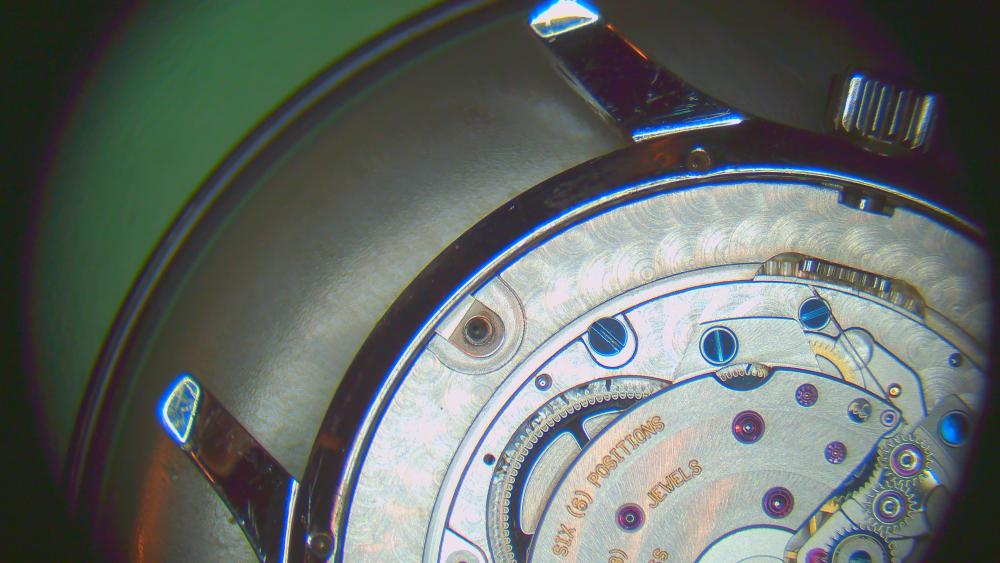
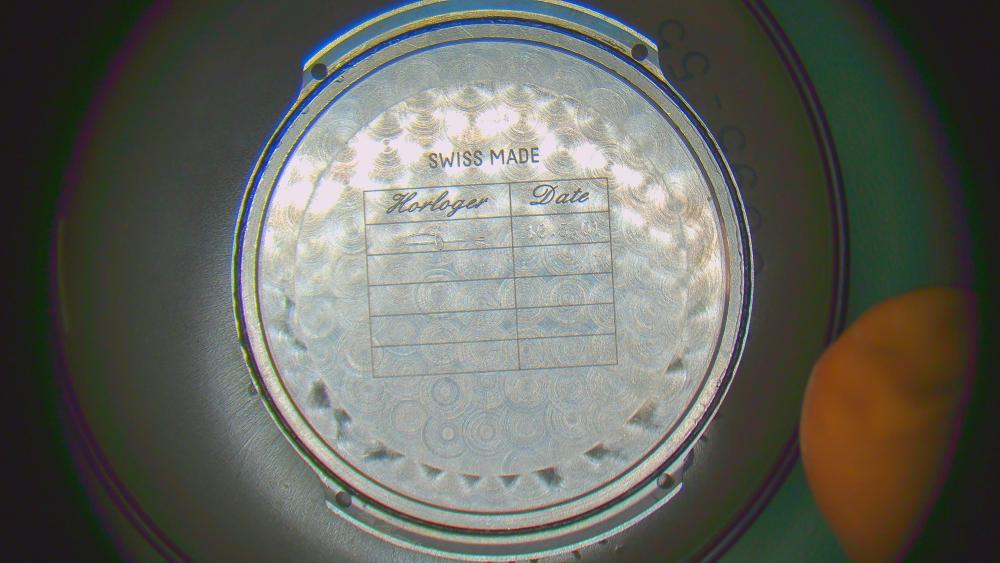
Good morning! My next walk-through. This time of an Universal Geneve 2-66 calibre in a "White Shadow" watch. With less than 2.5mm thickness, the movement was one of the thinnest automatic movements at its introduction in 1966 and for decades to come. Some say it was the thinnest of all, but I found the Piaget 12P was 2.3mm and introduced in 1960. That would make the Universal 66 the second-thinnest automatic movement unitl 1985 when the Frederic Piquet 71 came in with 2.4mm. ANYWAY, it's very thin! Another cool story is that no other than Patek Philippe poaches the movement engineer of Universal and let him basically copy the UG 66. They then introduced the Patek calibre 240 in 1977. They looks strikingly alike. Apparently, Universal sued Patek, but settled out of court and then went bankrupt during the quartz crisis. (see my post here for a picture comparison of the UG and the Patek: https://www.watchrepairtalk.com/topic/3470-which-watch-have-you-got-coming-in-the-mail-show-us/?do=findComment&comment=270754 ) As usual, I'll share the walk-through in several posts. Today: disassembly. Hands and dial off reveals the keyless works (two dial screws) Note: the dial washer doesn't fit too well. I'll look for another one for assembly. NOTE on letting the power down! The power is held by TWO clicks. One directly at the ratchet wheel (dial side) and one in the automatic works. I first completely removed the click at the ratchet wheel and then held back the click of the automatic works. It worked ok, BUT is not ideal. It lets the rotor spin to release the power in that direction (instead of the crown). I therefore suggest to first remove the automatic works completely (rotor, wheels and click). THEN proceed as usual by holding back the ratchet click and releasing power gently by holding/slipping the crown. To show the (supposed) better practice, I'll post my pictures in a different order from my actual disassembly. This is how I think it SHOULD be done (in retrospect), 0. Remove the balance 1. Automatic works: remove the rotor The automatic bridge (please ignore that the barrel bridge is already off and don't remove it before releasing the power!) VERY gently with this spring on the click! It's insanely thin. The end of the spring rests in a small hole in the mainplate. I'll show that in my pictures for assembly. Note that the wig-wag winding wheels for the rotor can stay in place. They are riveted to the movement. A total of three ball bearings here! Two are visible, and the backside of it (that wigs and wags) also has a ball bearing. The rotor also has one. So four ball bearings in the movement!! 2. Turn movement over and release the power with the usual method (hold back click and gently let the crown slip through your fingers) The click is here: Then disassembly the click I also took the hour wheel of (no picture, but obvious). NOW, IMPORTANT. The apparent cannon pinion here, is not a real cannon pinion!! It should be completely free. The movement doesn't have a central centre wheel and therefore the "true cannon pinion" also isn't in the centre of the movement. This "false cannon pinion" is just a reduction wheel for the minute hand. DO NOT have the stupid idea of tightening this "false cannon pinion".... like I did ... But ok, onwards. 3. After letting the power down, I go back to the train side. Note on pallet fork: the lock is very heavy. If amplitude turns out to be very low after service, I may have to push the pallets in a bit. Note that there a two different screws for the train bridge!! The one on the edge is a bit shorter. Barrel bridge. Again, note that there are two different screws! The one at the crown is longer. Now, the larger wheel next to the barrel is the decentralized centre wheel with cannon pinion. I will show how to disassemble it in a later post. The ratchet wheel is under the barrel 4. Dial side cover plate Watch out, under this wheel is basically the crown wheel. There's an outer crown and also a seat around the post. the downwards bent side goes down on the setting lever careful, very strong spring here this lever engages and disengages the integrated wheel directly with the ratchet wheel for manual winding Now again very careful with the spring under the lever! It is very thin and very springy. I actually lost it and couldn't find it even after 1.5h on the floor... and since I managed to buy one, there are now only very few left in the world! finally the stem with the pinions removing lower balance jewel for cleaning barrel open. NOTE that the square bit of the barrel arbor points up from this perspective (not pictured). This is important to remember for assembly. This concludes today's post of disassembly. Next post will show the disassembly of the integrated decentralized centre wheel and true cannon pinion -- and tightening it (because it was slipping).


 1 point
 -
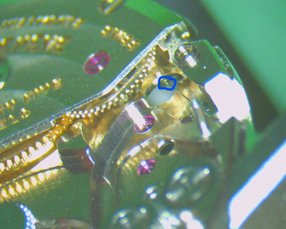
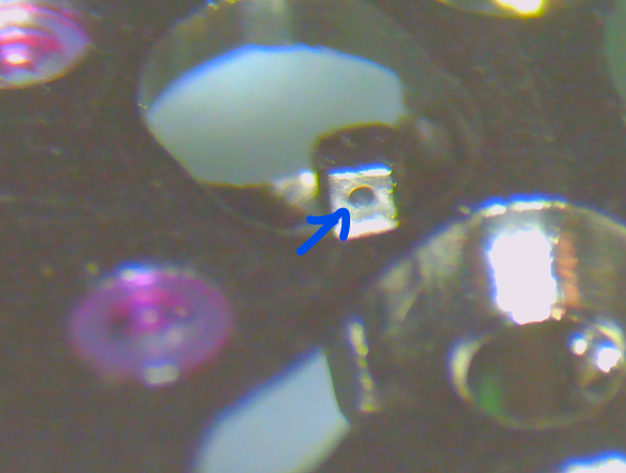
What is the function of that pin? They have changed the construction. The older ones don't have that pin:
 1 point
 -
I also use my finger to block the wheel. Apply the same torque as on bridge screws1 point
-
1 point
-
I think it was on a Dean DK video about gravers that he was using 45 degrees for roughing but finish was good and 20 degrees for finishing. i’m going to upset you now Rich, I have got TWO cross slides now Tom1 point
-
Yeah I thought the angles were way to steep, they were the only ones I could find, I changed the angles straight away. Save your cash you'll need every cent to put towards the crossslide1 point
-
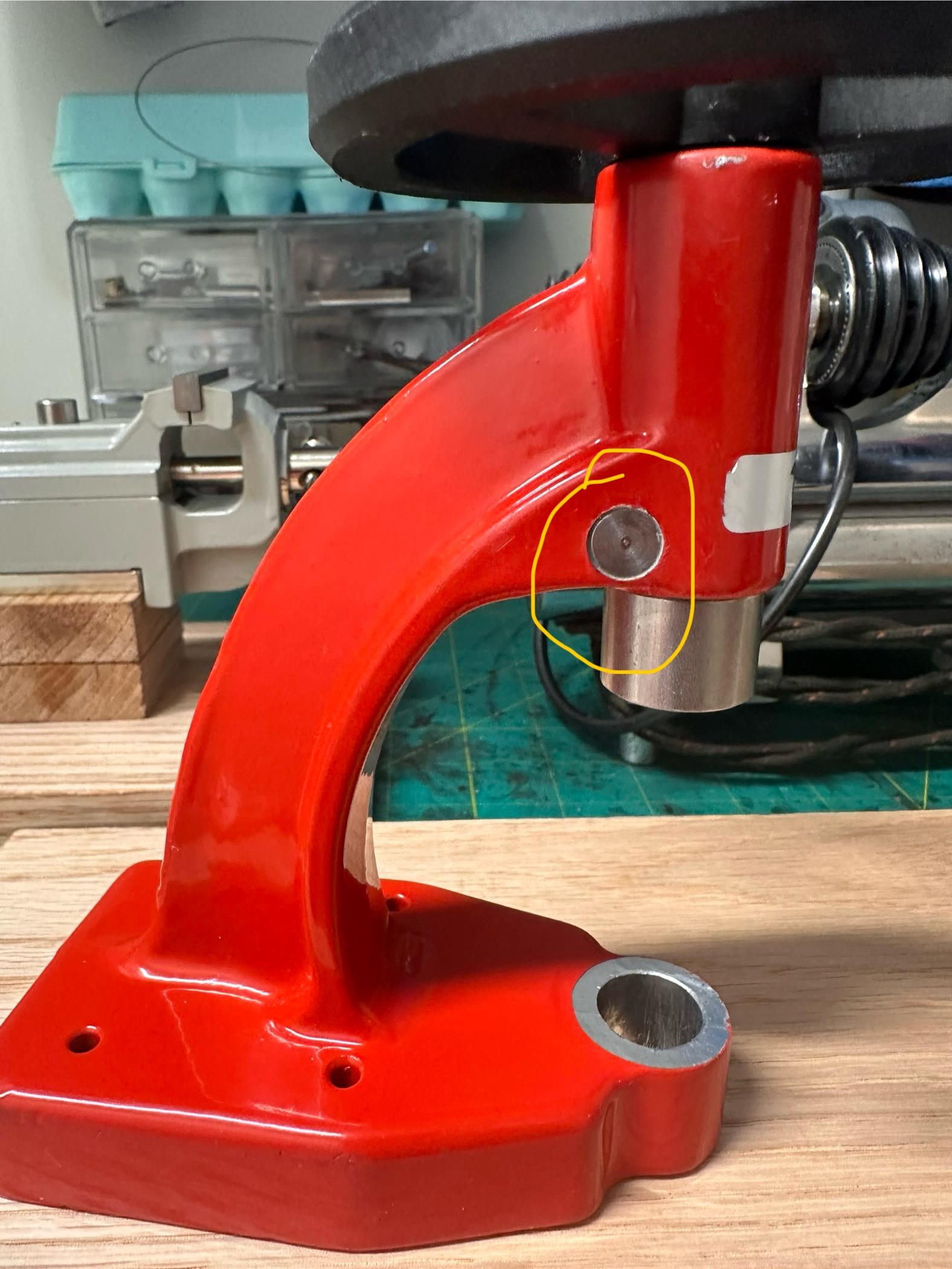
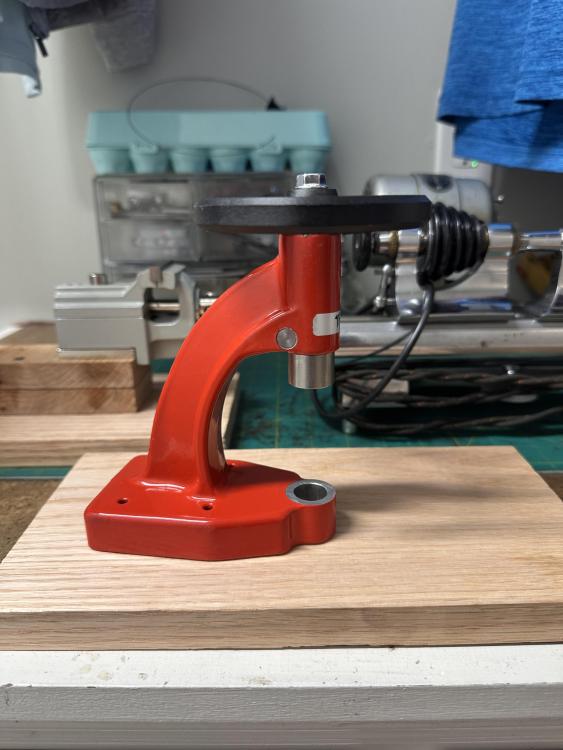
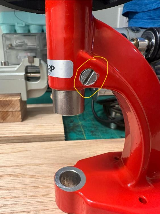
Here is an update on my Robur press. They emailed again and said they are still waiting on the manufacturer to confirm if they would issue a refund or a return of the tool. Since it had been three weeks from the time I made my complaint, I told them not to worry about it, and that I was going to try to fix the tool my self. I put it apart and replaced the pin that goes across in the spindle hole. I guess it was to thin creating to much space in the spindle hole which would cause an excess of side shake. I went ahead and drilled the old pin out, turned a new one from tool steel and replaced it. I am more than pleased with the results. The side shake it’s from super very little to none now. And it is super smooth when turning the wheel on the top to make the spindle go up and down. I am going to buy some paint that matches the original to paint the new pin. Here are some pictures of it now:

 1 point
 -
If you look vertically down on the spring between stud and adjuster, you can see where it is twisted slightly from the light reflection. I find this adjustment easier with the balance mounted on the movement. You can then see when you have adjusted it enough. (Of course you will turn the tweezers the other direction working from the top)1 point
-
This stones look to be not pressed, they are probably rubbed in. So jewel press is something useless here if this is as what I think. If You show picture of the plate with the broken jewel from the bottom, it will get clear.1 point
-
Thanks a lot @Knebo ! Thank you for this wonderful gift! I really appreciate the excellent documentation you wrote !1 point
-
Yeah neither would get out of a Glasgow pub if they put on that accent, well not in one piece anyway Tom1 point
-
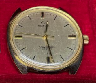
I was able to find an original link to repair the Speed master bracelet but I also ordered a repro bracelet from Uncle Seiko. I have a magnet sign on the back of my truck. Wanted men's watches working or not. That's how I got this great group. Speedmaster is 1972.1 point
-
Pressed onto the flat top but using a finger seams like a better option.1 point
-
So do you press it down on the flat top of the ratchet wheel or do you jam it in between the teeth? That sounds like a safe method, and since the finger will cover a rather large portion of the area I guess it will give enough counterforce. I'd be happy to try that. Even if we were to tighten the screw a bit too loosely, I assume the risk of it coming off is small since it continuously rotates and is tightened in the clockwise direction of the ratchet. Still, it would feel safer to tighten it a bit harder than I usually manage.1 point
-
This makes me think back on a HD liberator motorcycle engine I overhauled some 40 years ago. The workshop manual we had only specified 3 torques: tight, very tight and extremely tight . For watch repair however, we have " extremely light". As already mentioned, you develop a feeling for it (which I'm sure you already have yourself) safely staying away from any breaking point. I use an old pair of brass tweezers to hold the ratchet wheel while tightening.1 point
-
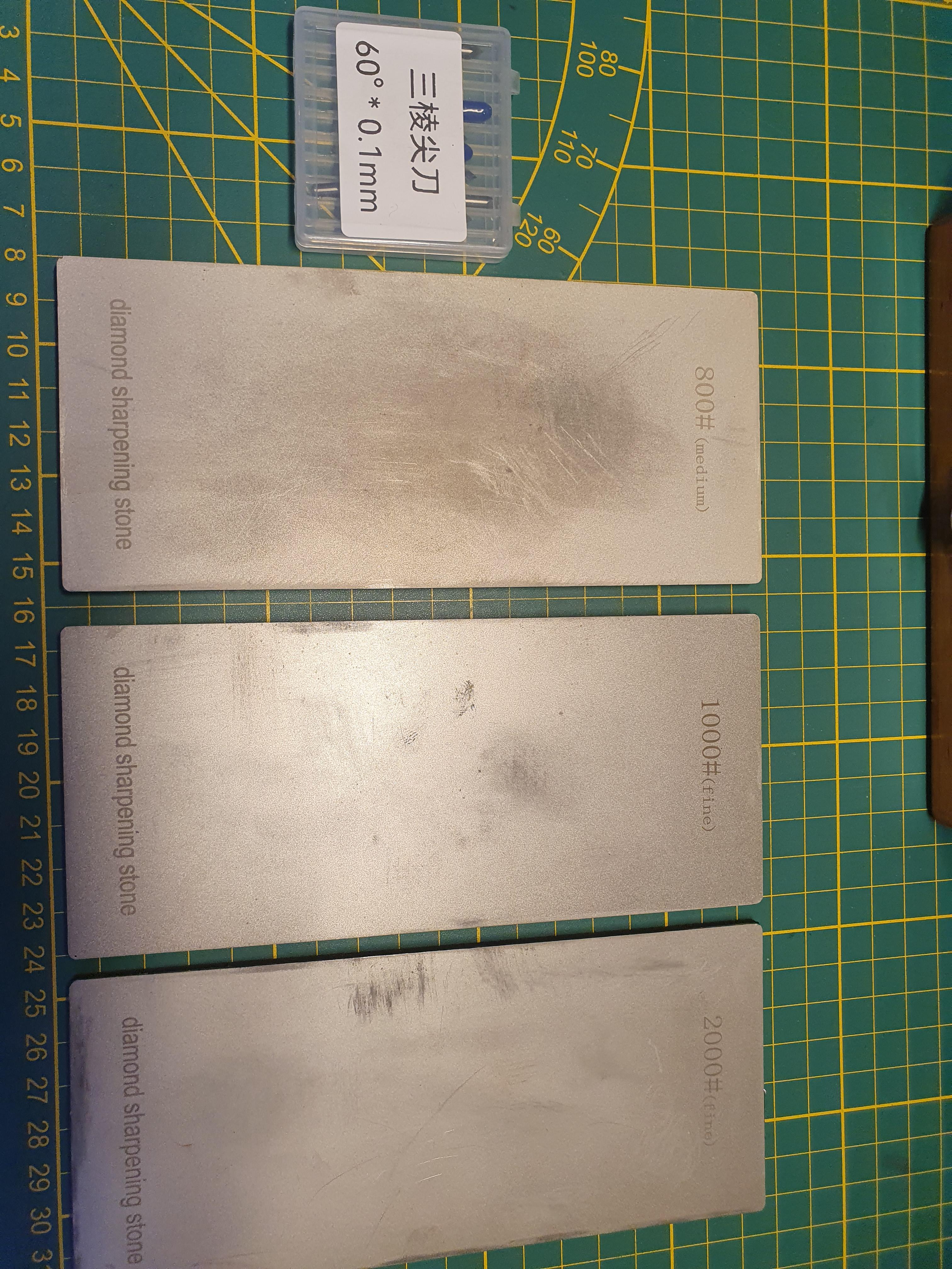
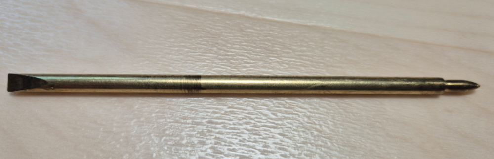
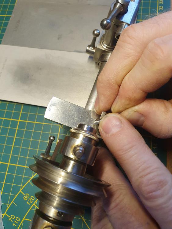
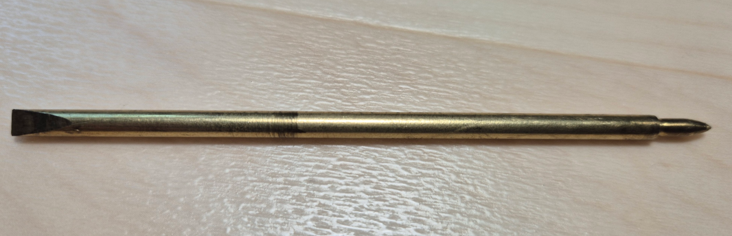
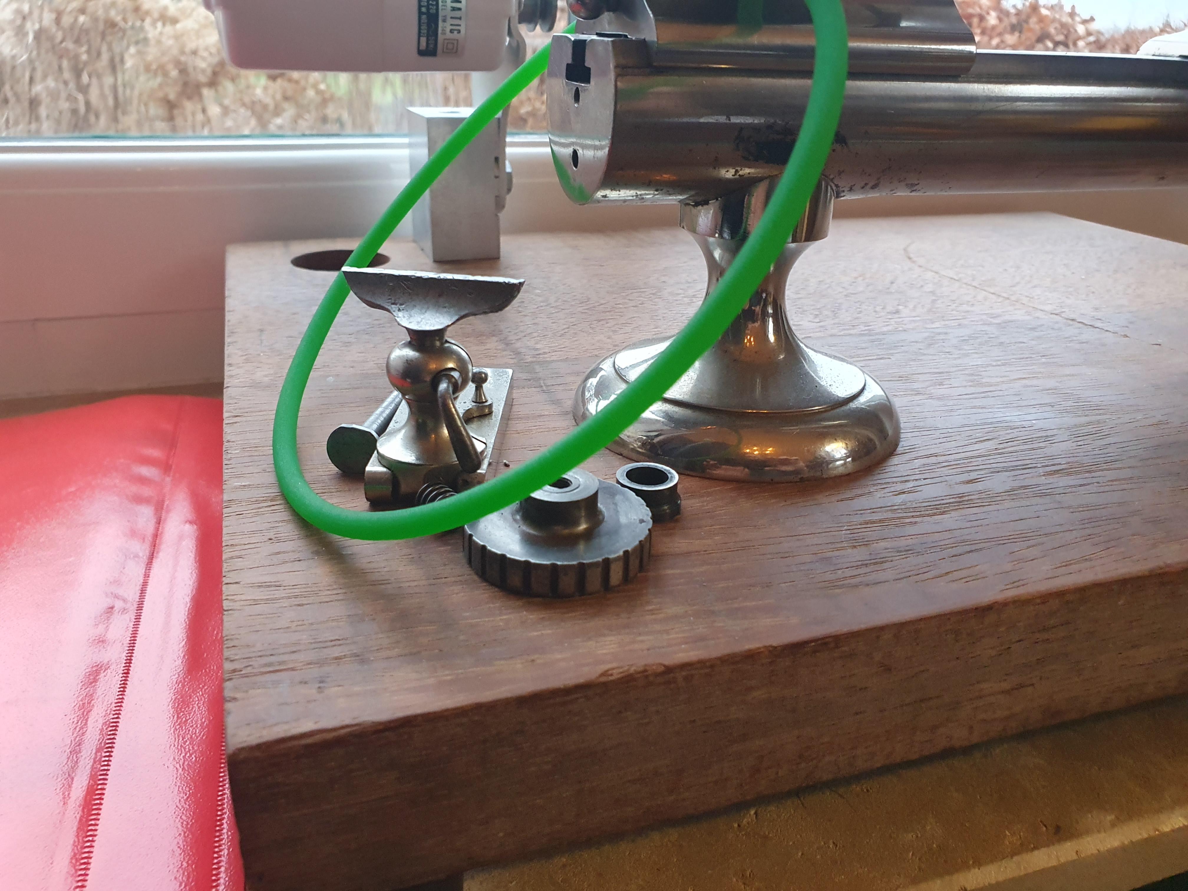
I use the 60 degr. 0.1mm type. For sharpening or reshaping I use these diamond sharpening plates (see pic.) I use these gravers without any handle. Holding the end between 2 fingers of my right hand and keeping pressure on it with the index finger of my left hand gives me all the control I need. The motor for my lathe is a simple sewing machine motor.

 1 point
 -
We just develop a feel over time of how tight screws should be, I generally pause momentarily when the screws reach the end of their threads and then an extra little nip up. The same method I've used for the last 45 years but on a much smaller scale. Whereas the average wood screw or machined screw takes the driving force of our wrist, forearm and upper arm even our shoulders come into play with heavy gauge long screws to send them home. Watch screws only have to deal with the torque we can apply through our fingers. I would say the size difference is comparable.1 point
-
This is great, thank you. A relief that I will at least not spend too much on gravers and sharpening equipment (and time and practice at that part) to just get started with the lathe. It looks like these can be bought with 30°, 45°, 60° slopes. What do you recommend staring with? @Razz & @Neverenoughwatches I will come back with unboxing photos when it arrives.1 point
-
I usually jam a homemade brass oiler into the teeth of the ratchet wheel and crown wheel. Brass is softer than the steel teeth, so it is less likely to damage the wheels.1 point
-
What about hands on the Cosmic?1 point
-
I do use Photobooth for snaps. But you do need to make the settings flip your image to normal. You can also turn off the annoying countdown as well, or at least use a button combination that bypasses it. (ChatGPT/Google Gemini are your friends) Otherwise I just take a screengrab from Quicktime (cmd/shift/4)1 point
-
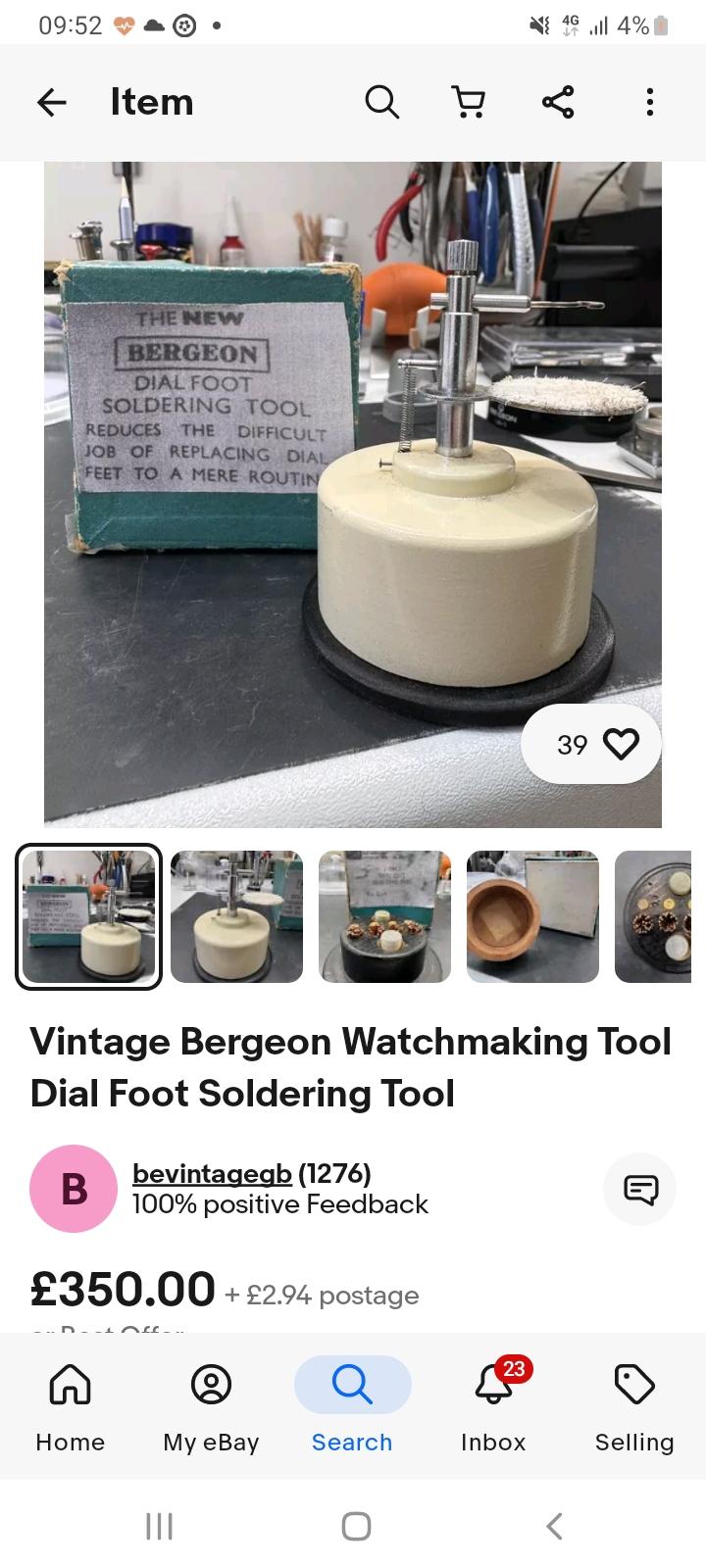
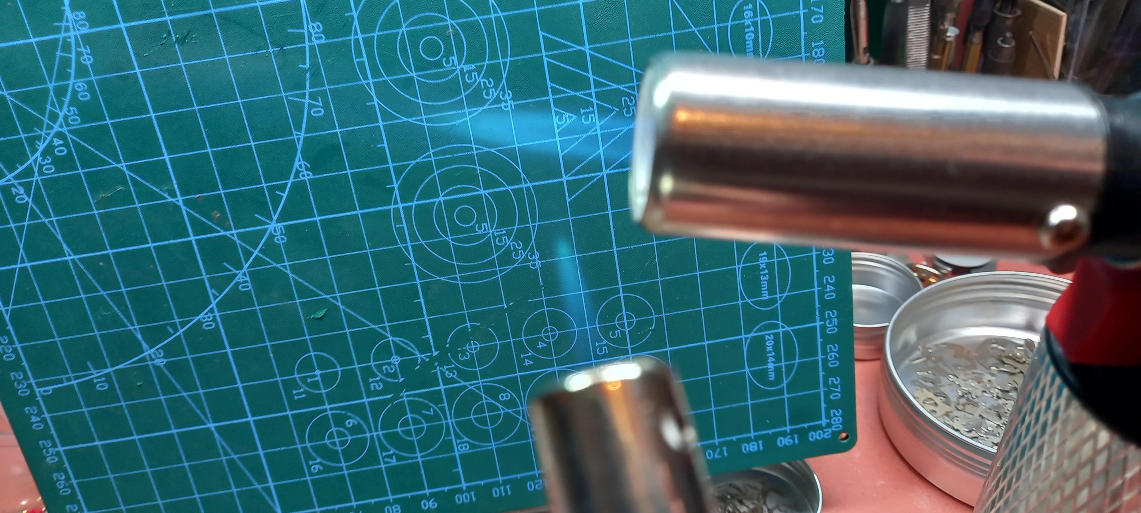
So I do have one of the Bergeon dial foot soldering devices, fortunately it was cheap( they usually are not ), its convenient but totally unnecessary, as you can knock up something quite simple yourself. I don’t tin the wire,but i don't see why that wouldn't work ok. My method i think is the same as Hector's.....I mark up the center position of the wire on the dial with a round burr first before I clean up the dial...otherwise you lose the positioning..then you have to guess. I then cut a 2 inch length of 0.7mm copper wire, set its position on the dial and add some bismuth paste to the join. Heat the top of the wire and watch the heat travel down the wire to the solder. Its easy control the heat adding and removing it to the wire as required, keeping a close eye on the solder.
 1 point
 -
Do you also need stems?1 point
-
Thanks a lot! Good memory about that washer! No, I didn't. It doesn't show up in the service manual and it didn't really fit anywhere. So I just assume that it came from somewhere else.1 point
-
pictures, please11 point
-
Well on this picture it is clearly seen the hairspring is bent up. Probably the other side goes down and rests on the balance arm. The other thing to check is if there is some axial free play of the balance. OP, just replacing parts without understanding what is needed for their correct function in watchmaking doesn't work. The mechanical watches are not made with 'plug and play' parts. So if You replace part and the movement doesn't work, You start diagnosing as if it is movement with unknown problem. You need to be prepared to discover any problem.1 point
-
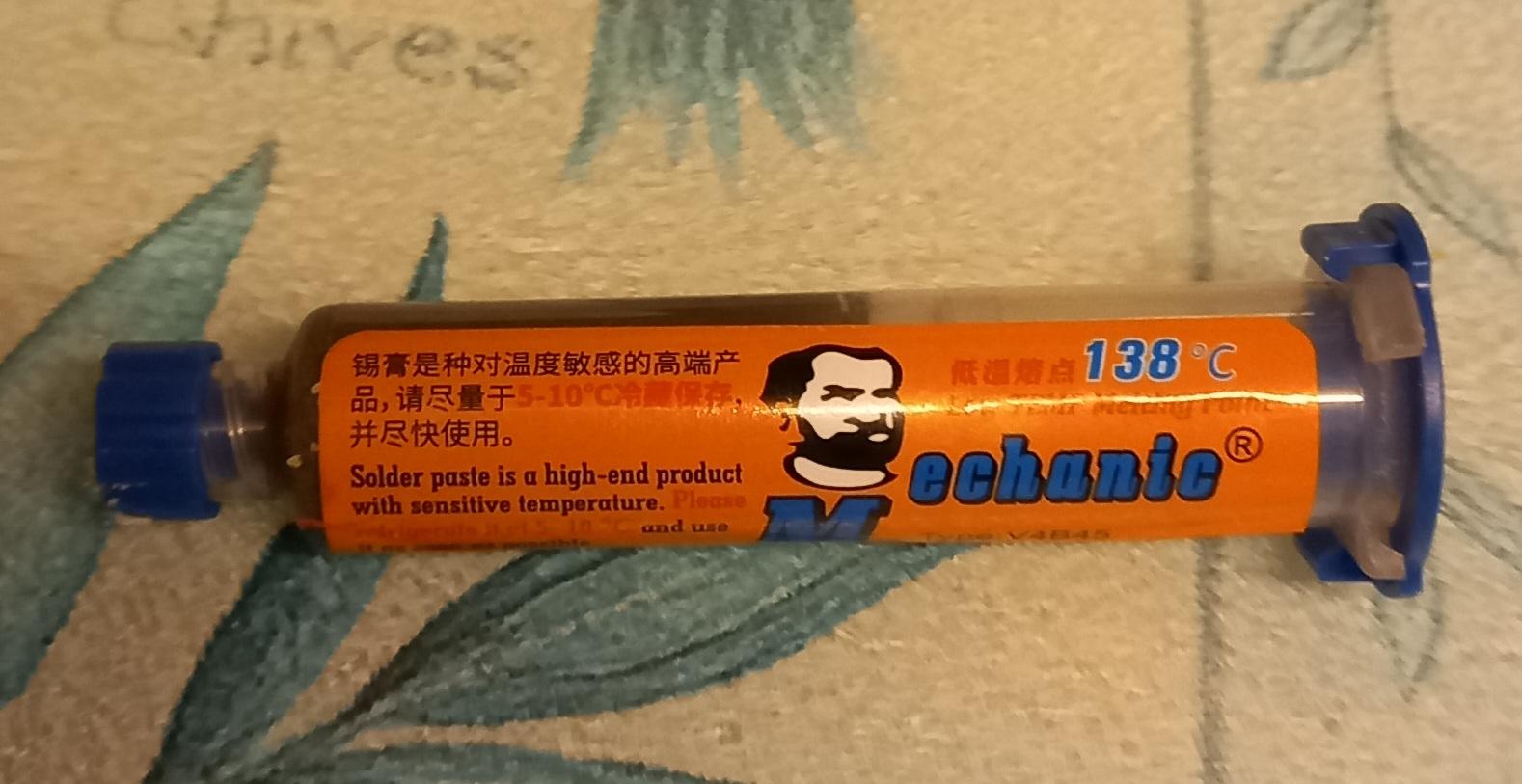
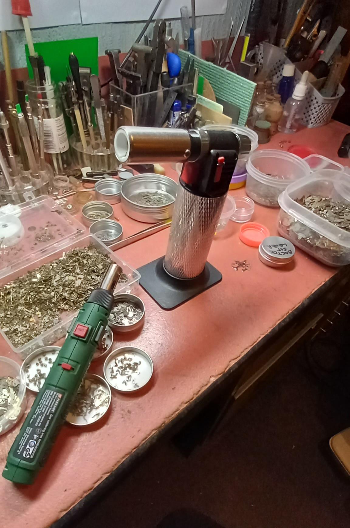
So any soldering need to have a clean surface to bond properly. Use wirewool or fine wet and dry on the dial where the joint is to be had. Add a small amount of flux...for belt and braces I use a self cleaning flux as well. For the torch I use a small gas powered soldering iron , a creme brulee torch might be overkill, you might even get away with a lighter ? This is the bismuth paste I use, just cheap bought off the net. I've had mine kept in the fridge for three years, just tried it and its still soft like it was when I bought it.

 1 point
 -
Try a low fusing solder paste. The flow is much better.1 point
-
I did see that on your videos @Dell. The ones sincere/1set tout look pretty much identical to the Jack and other equivalents but for several times the price. Tom1 point
-
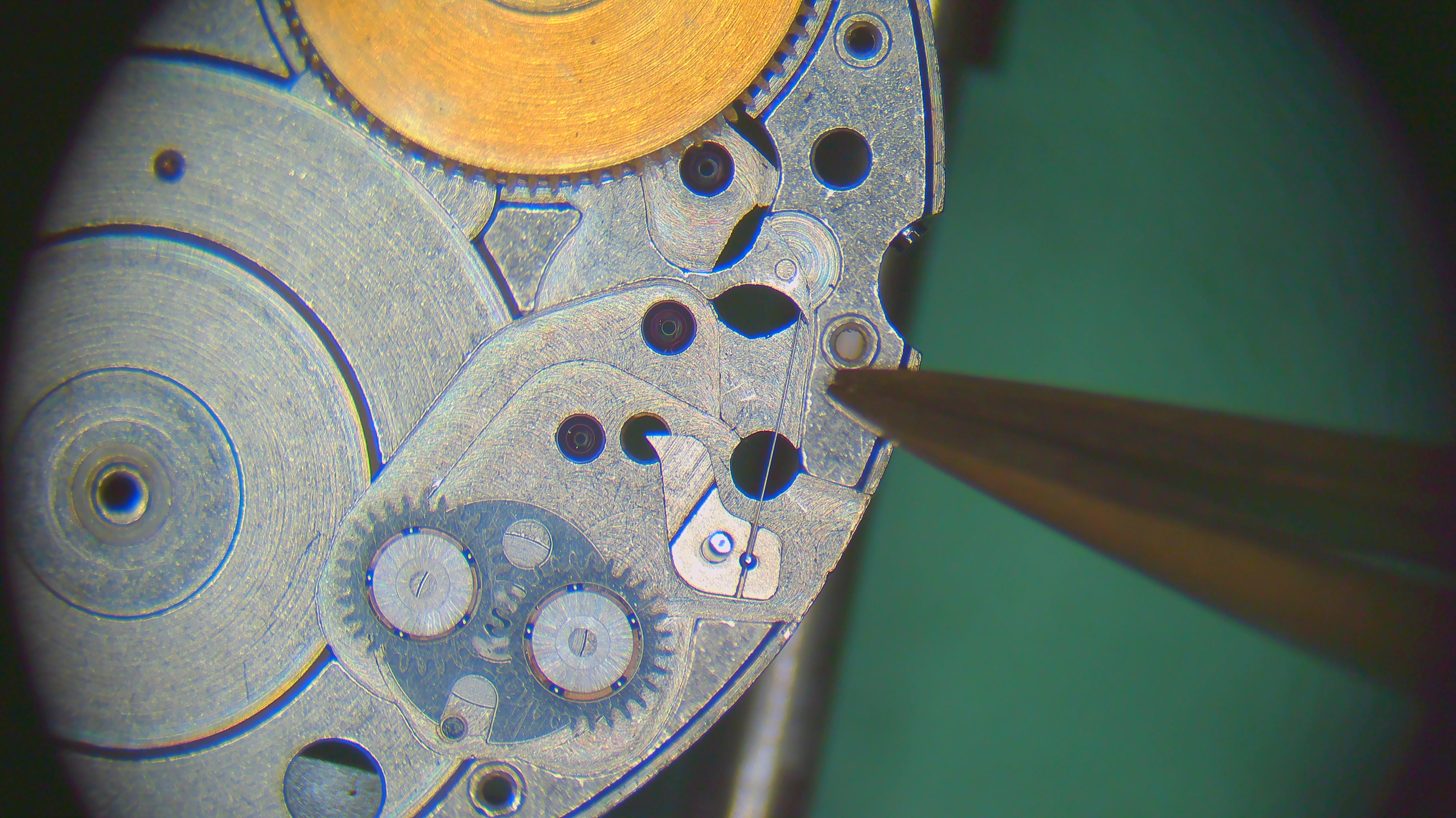
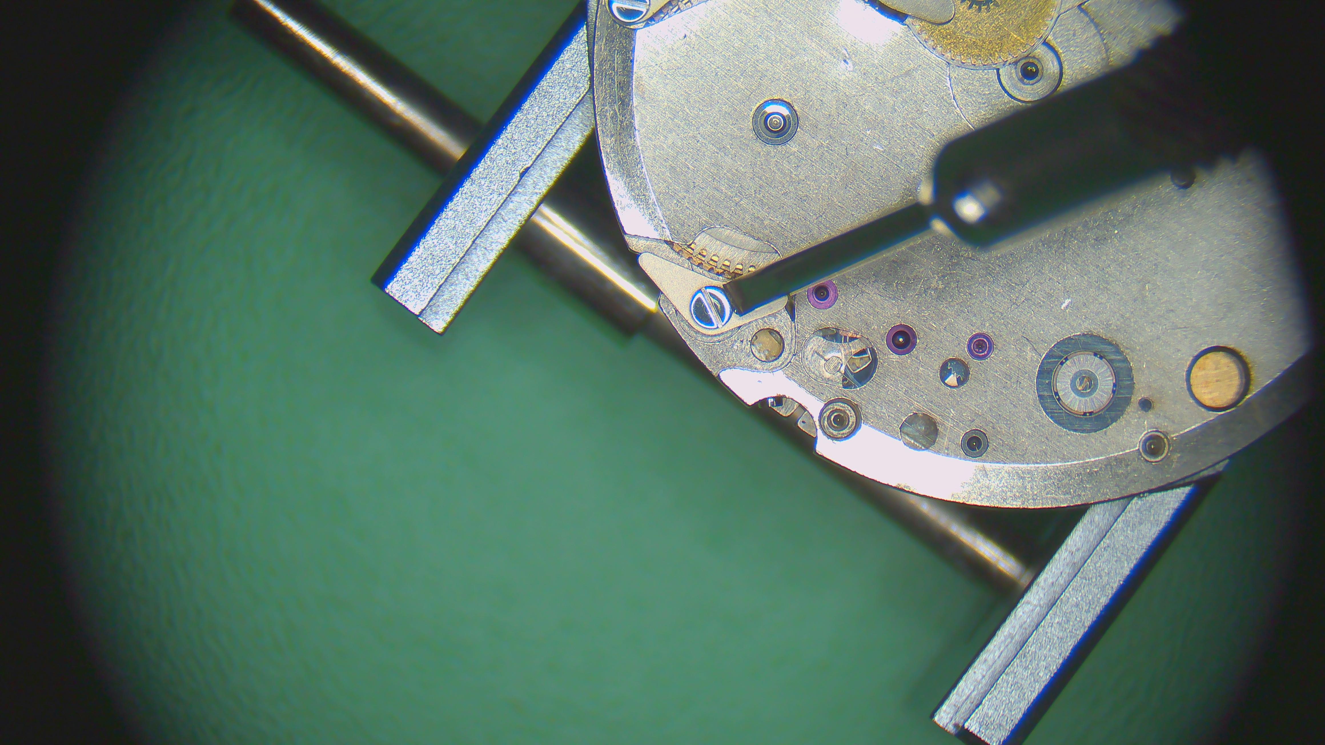
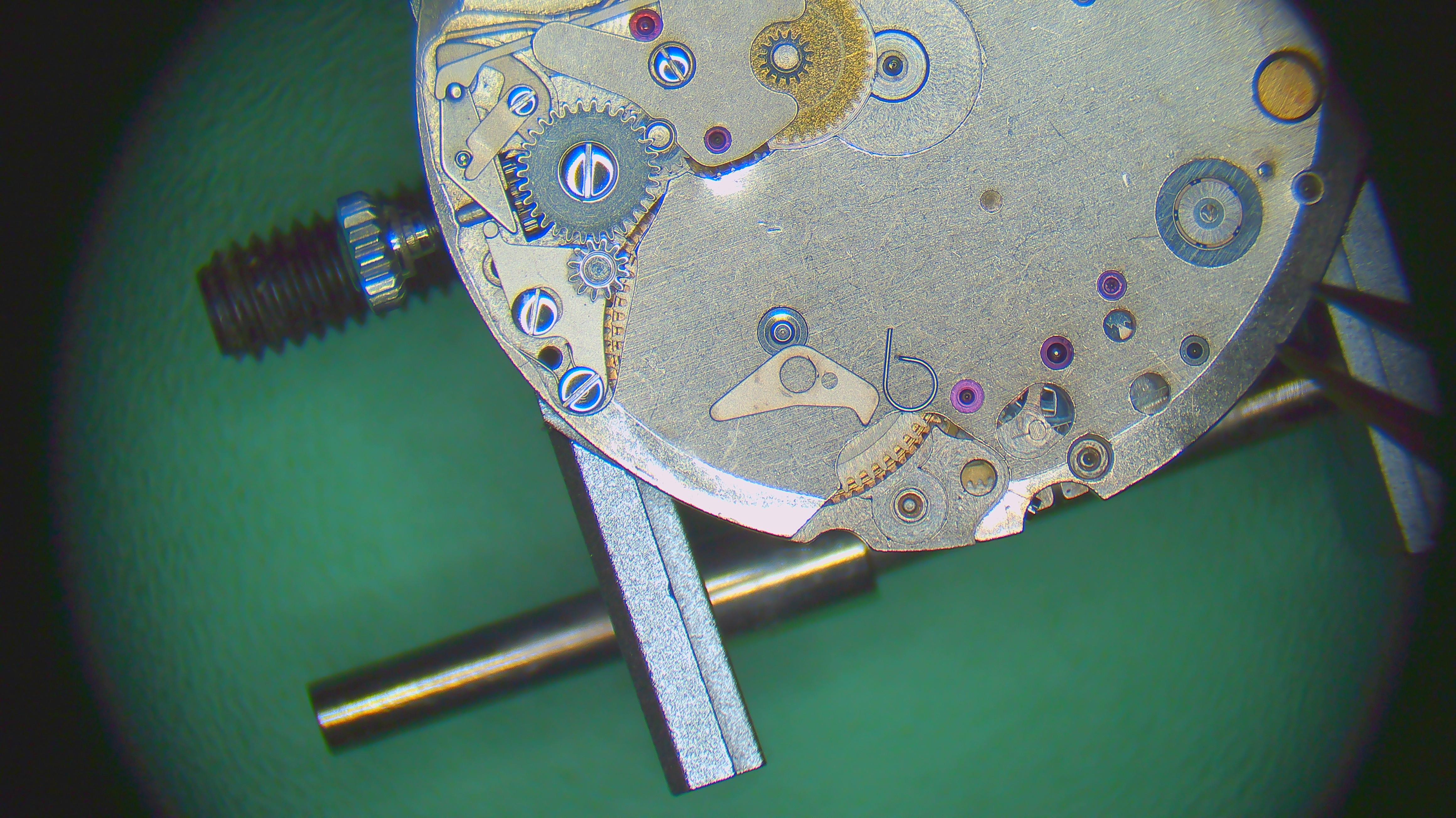
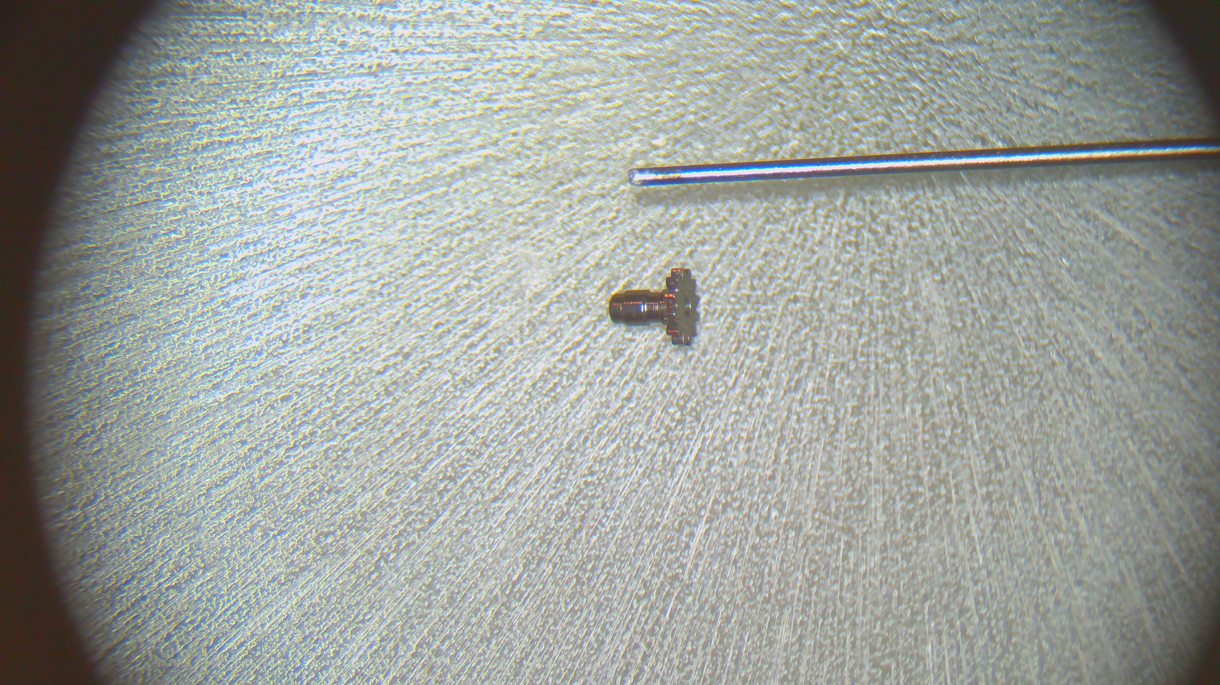
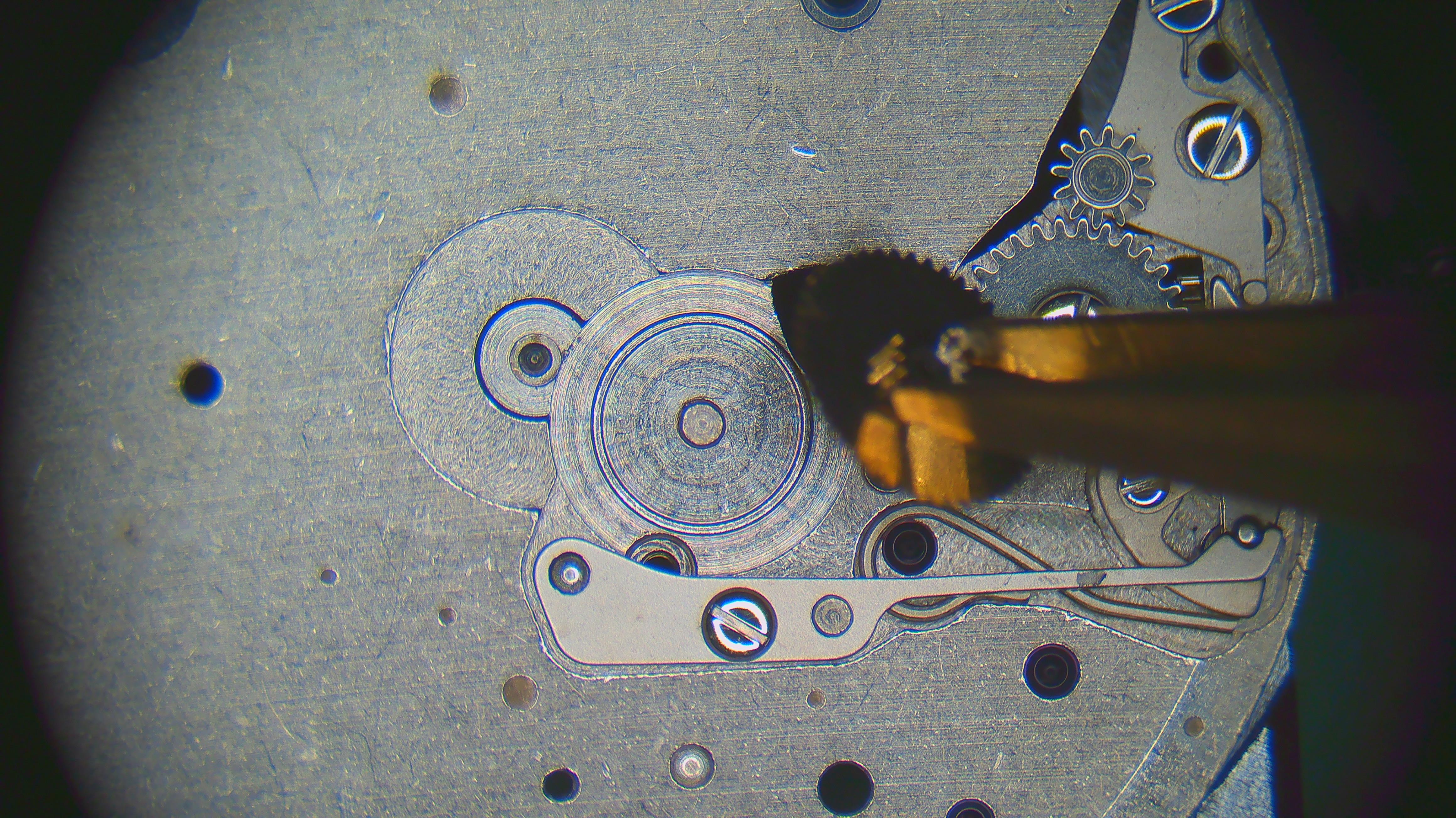
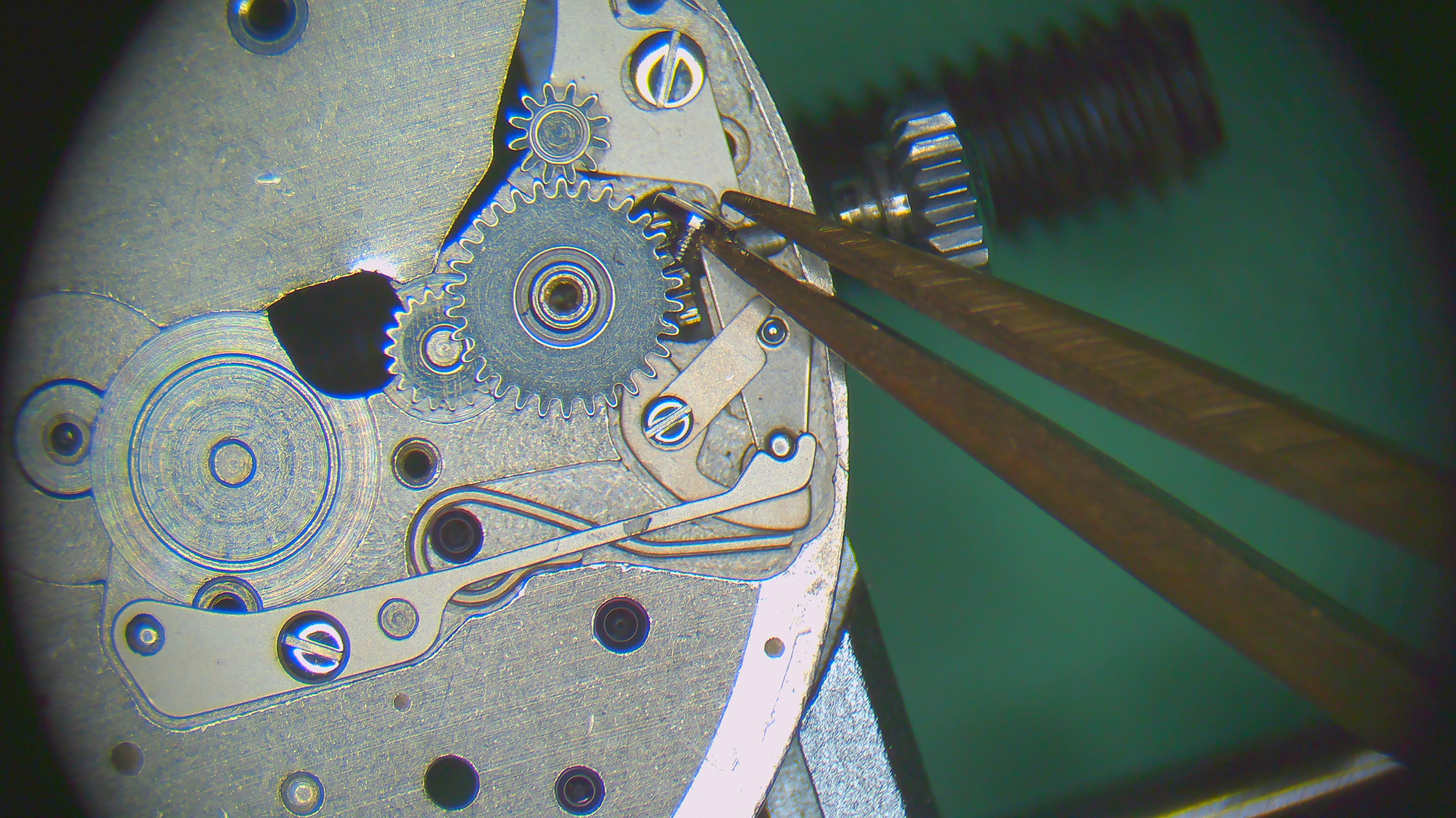
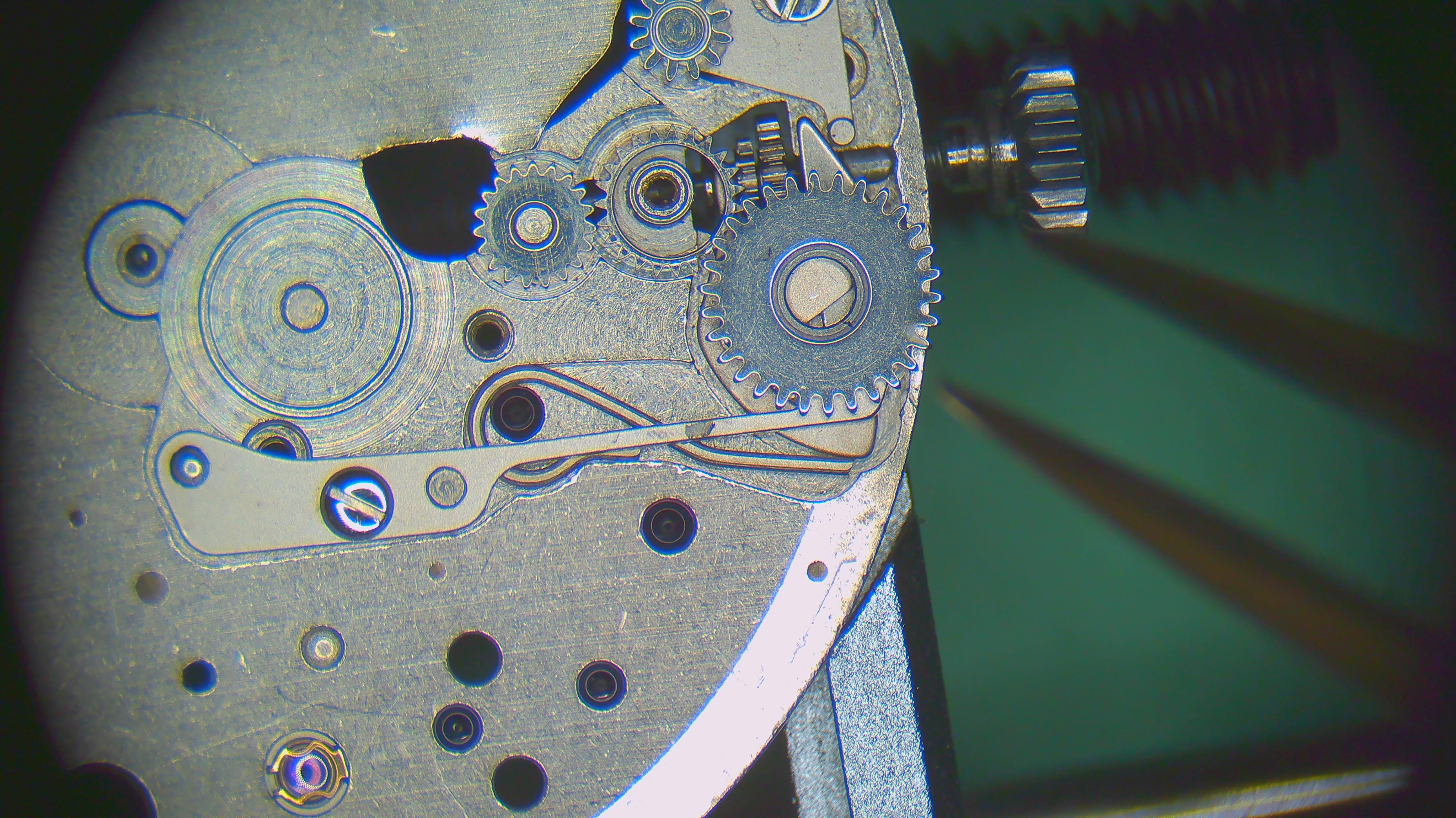
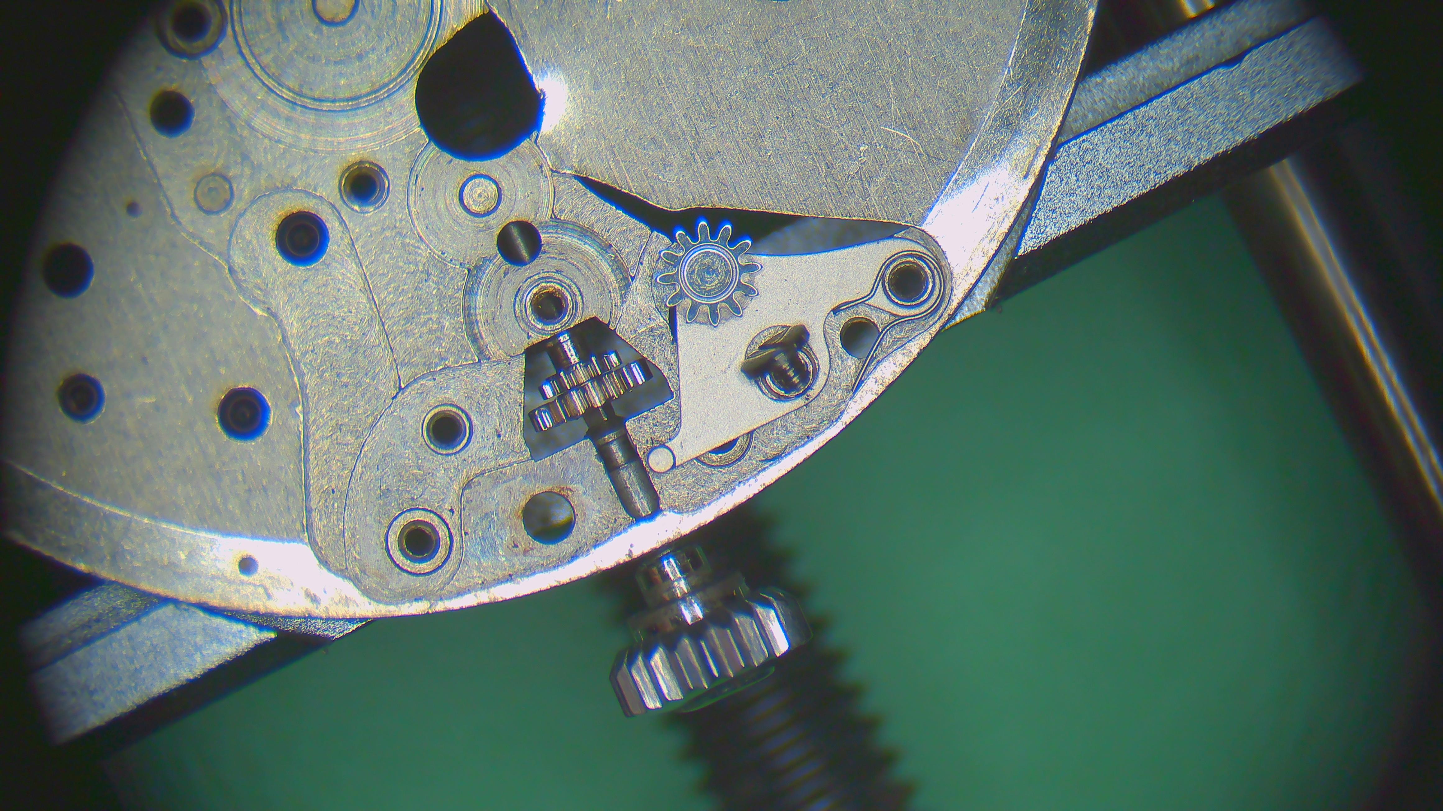
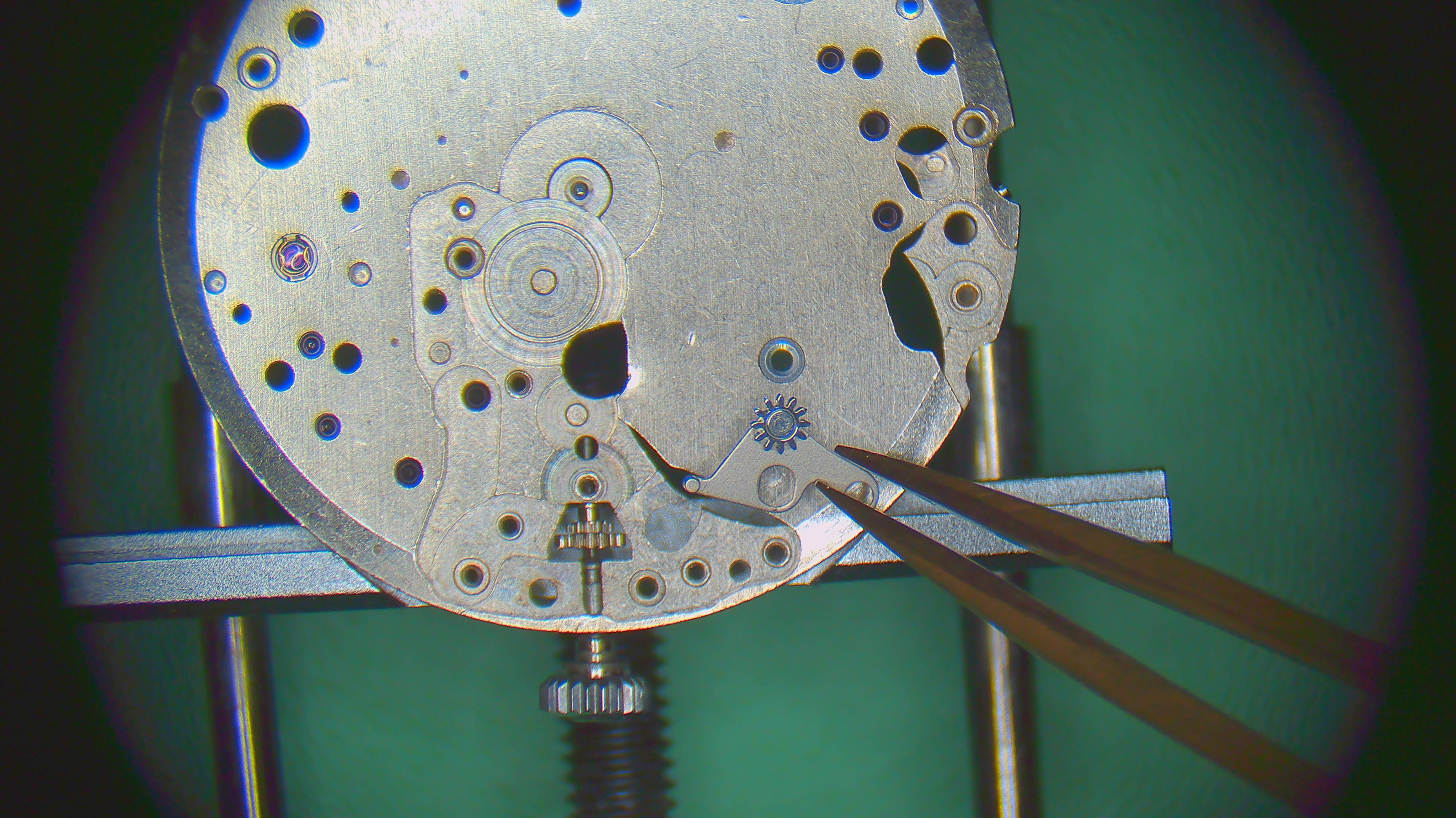
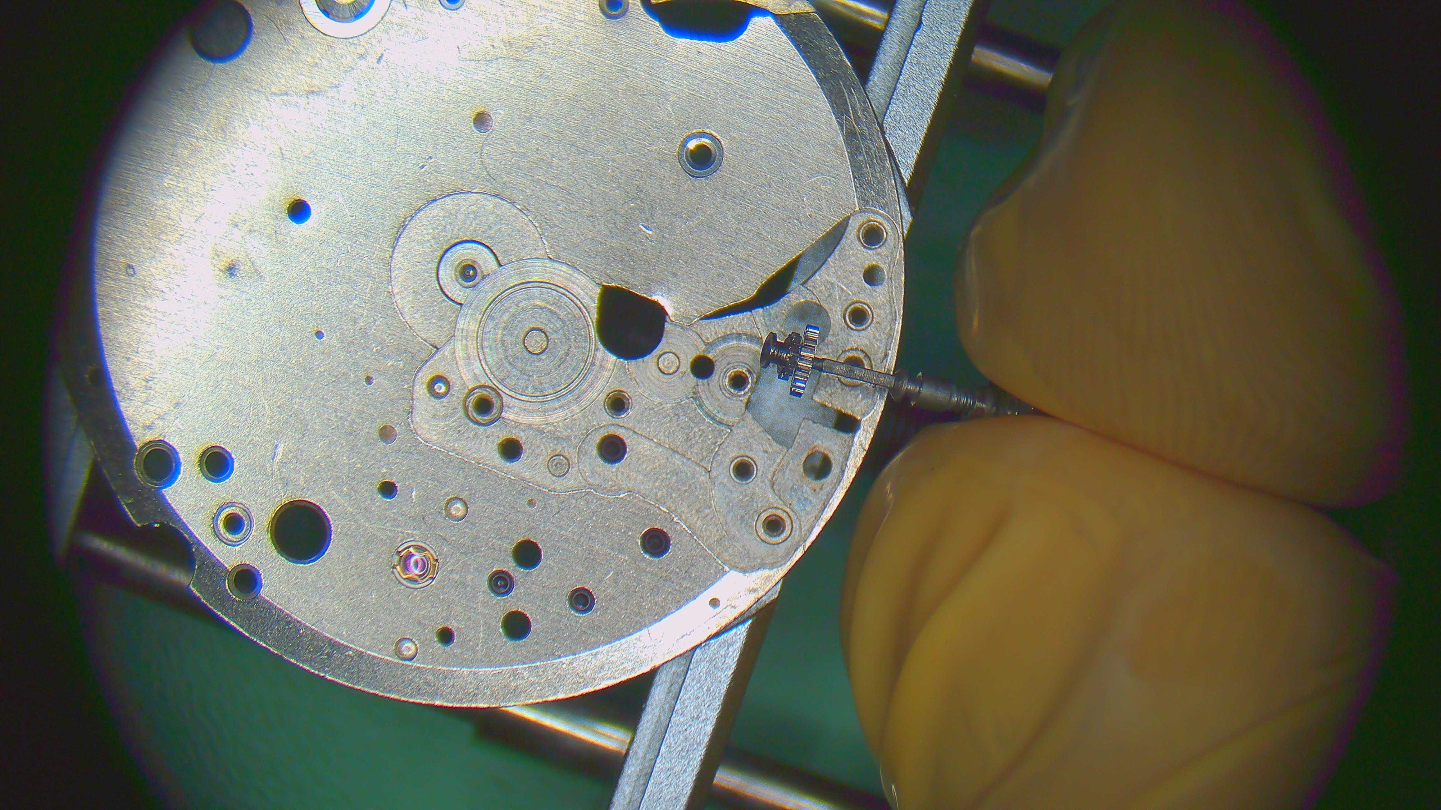
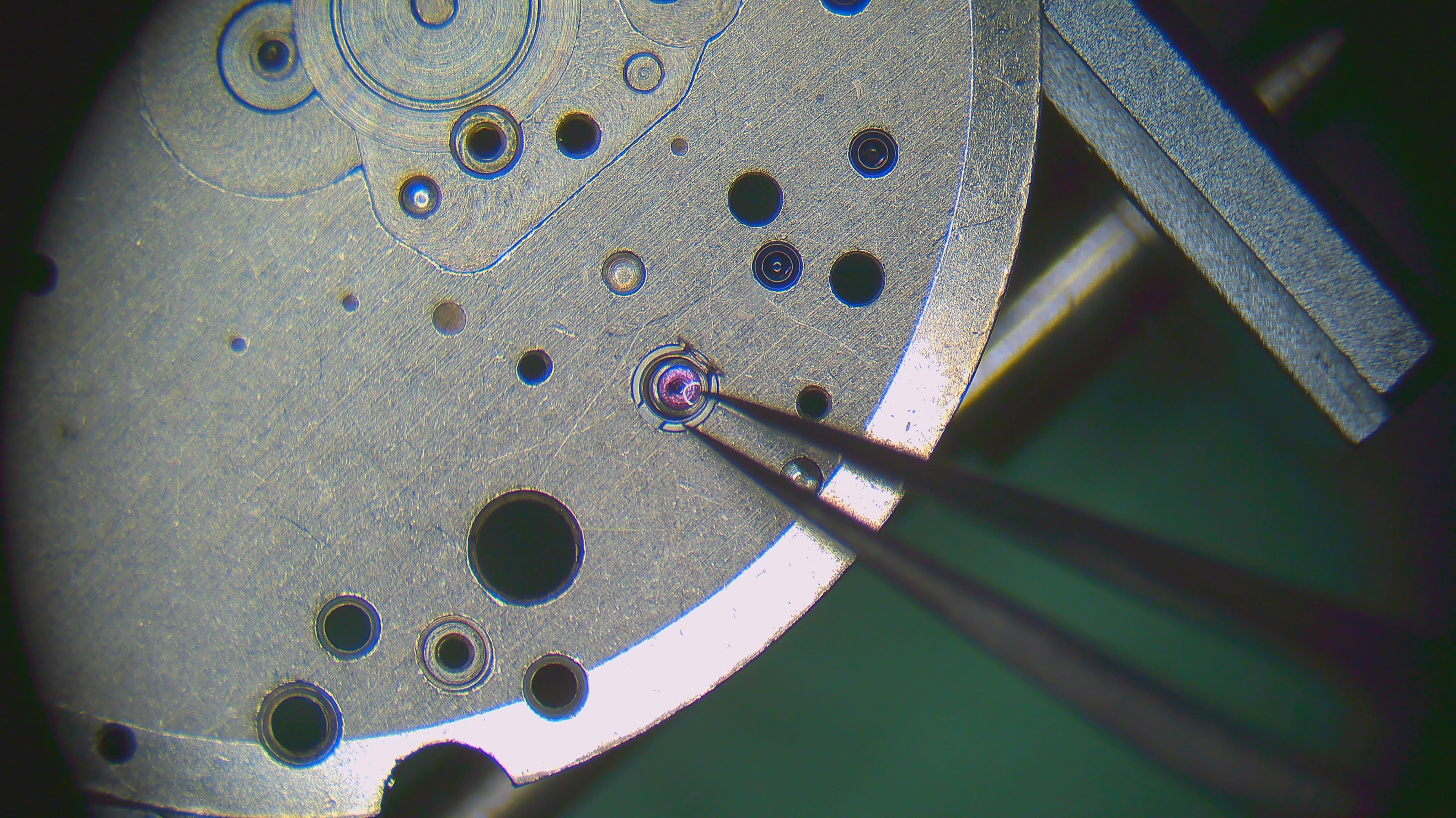
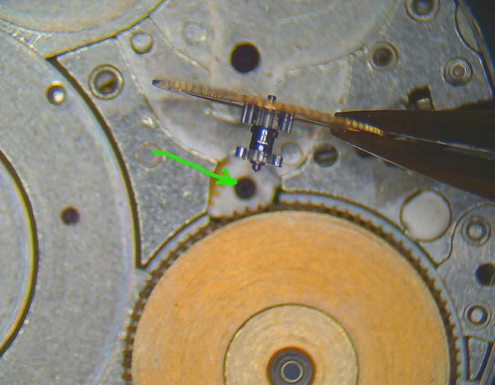
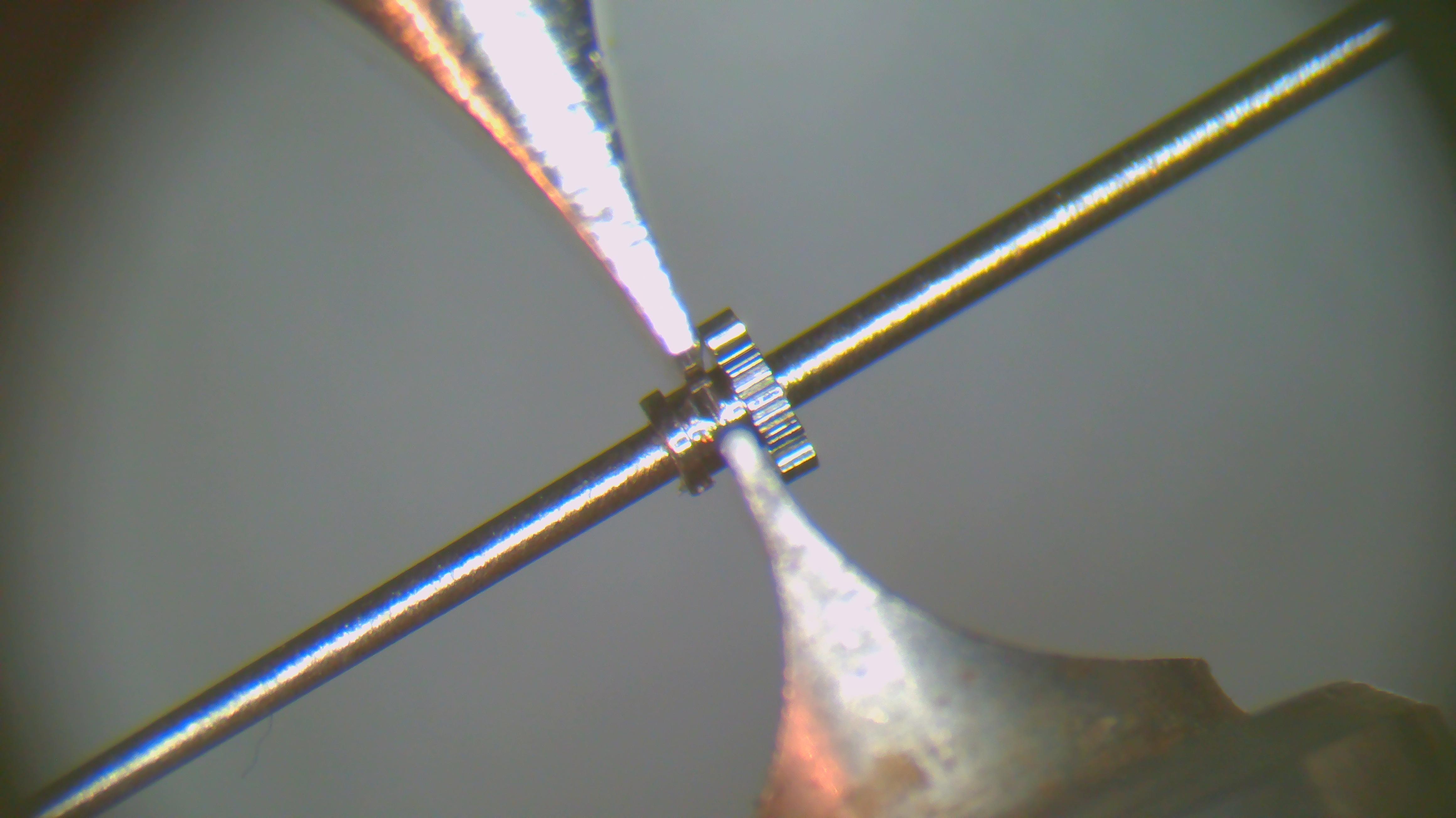
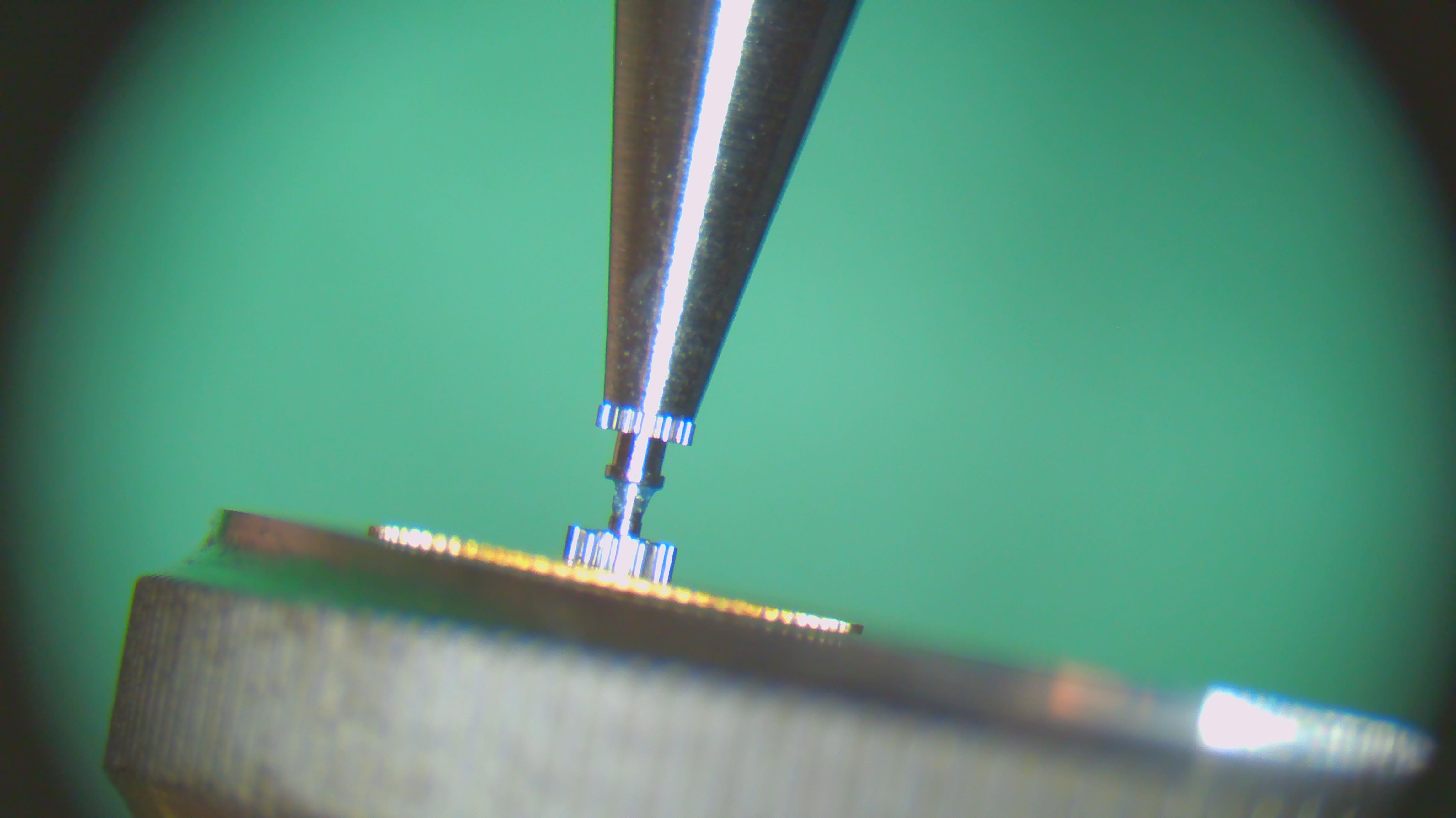
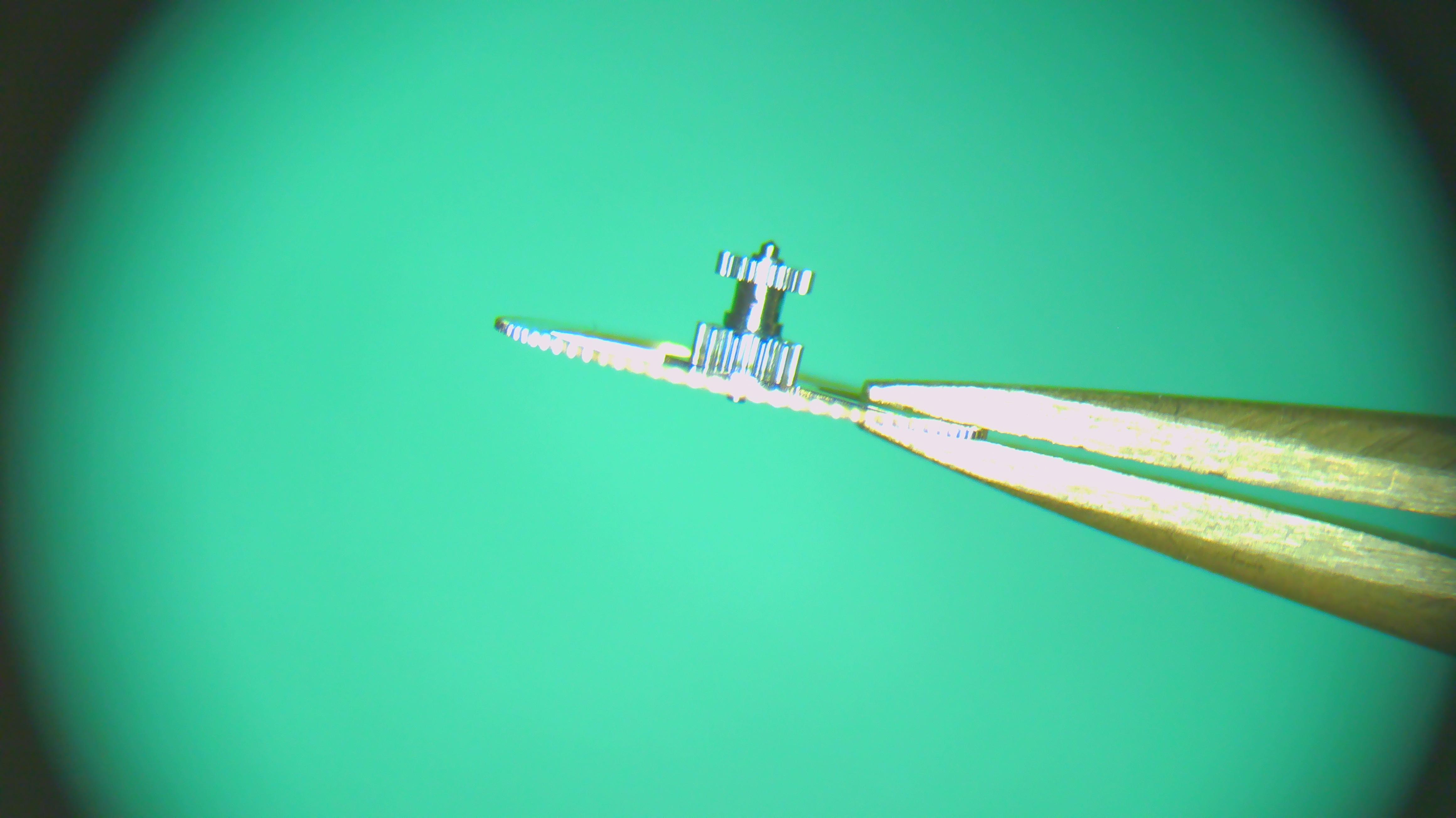
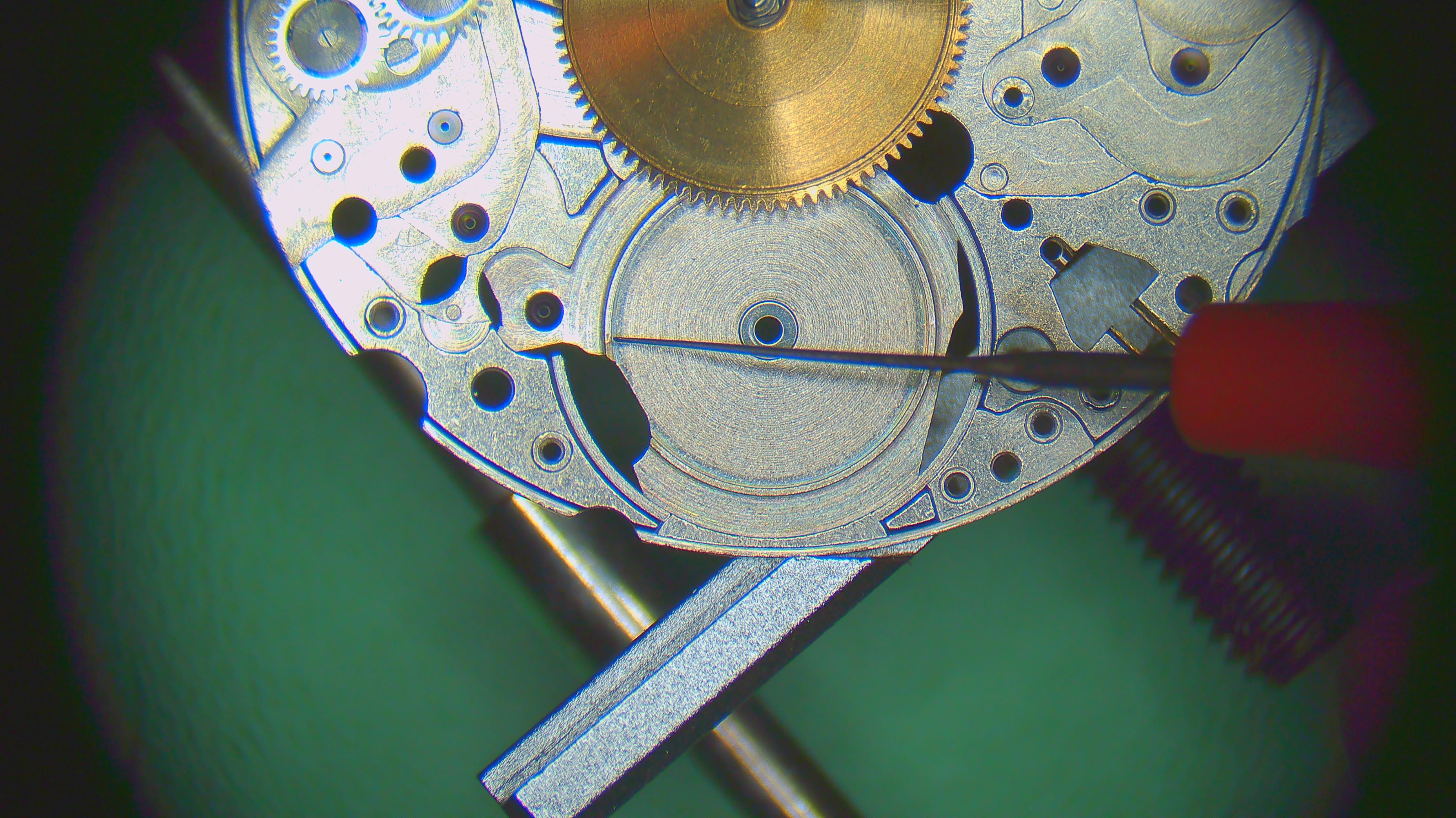
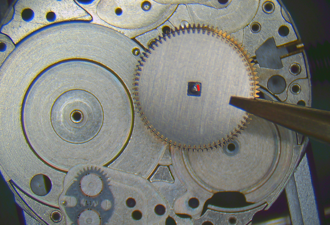
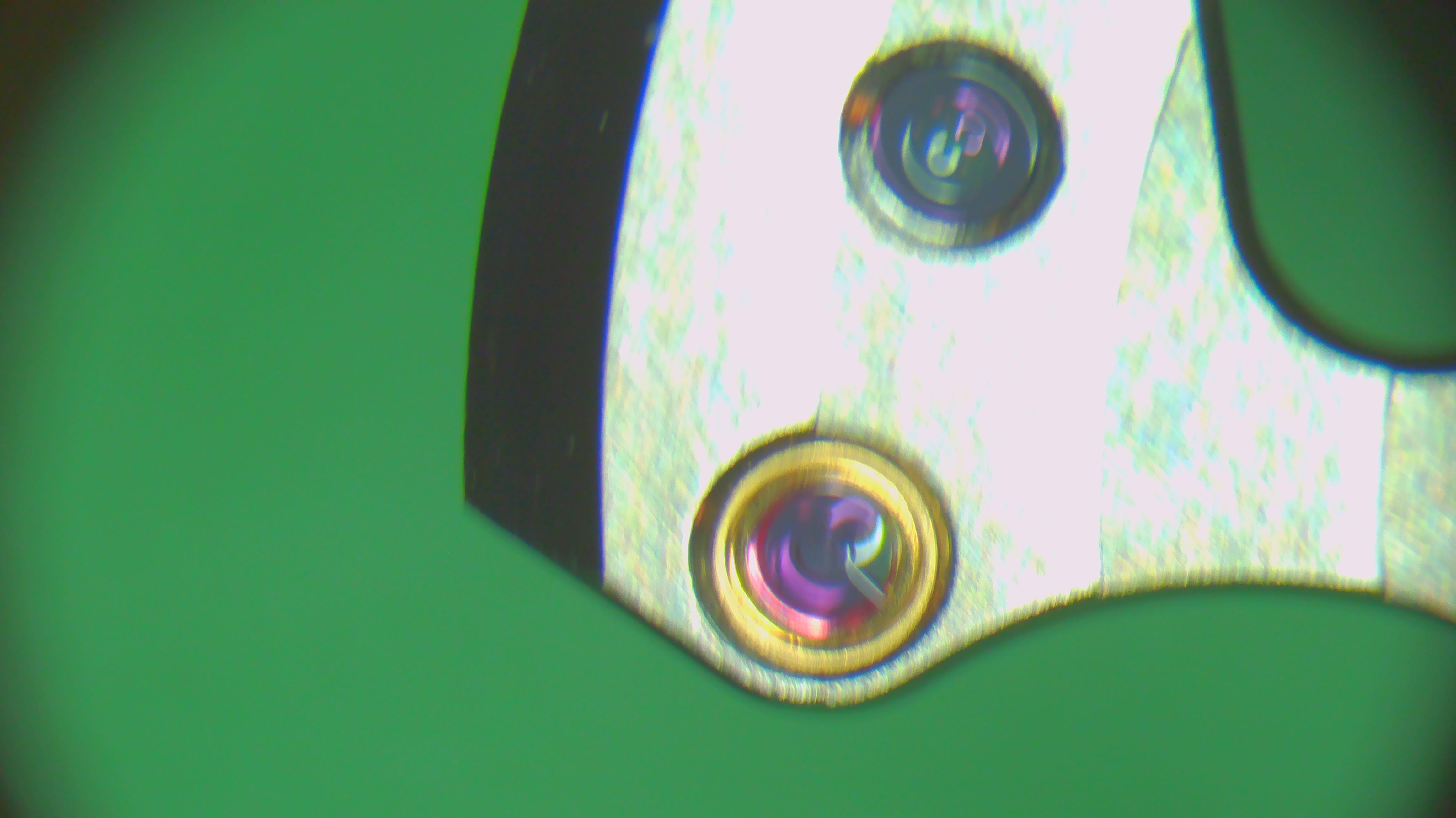
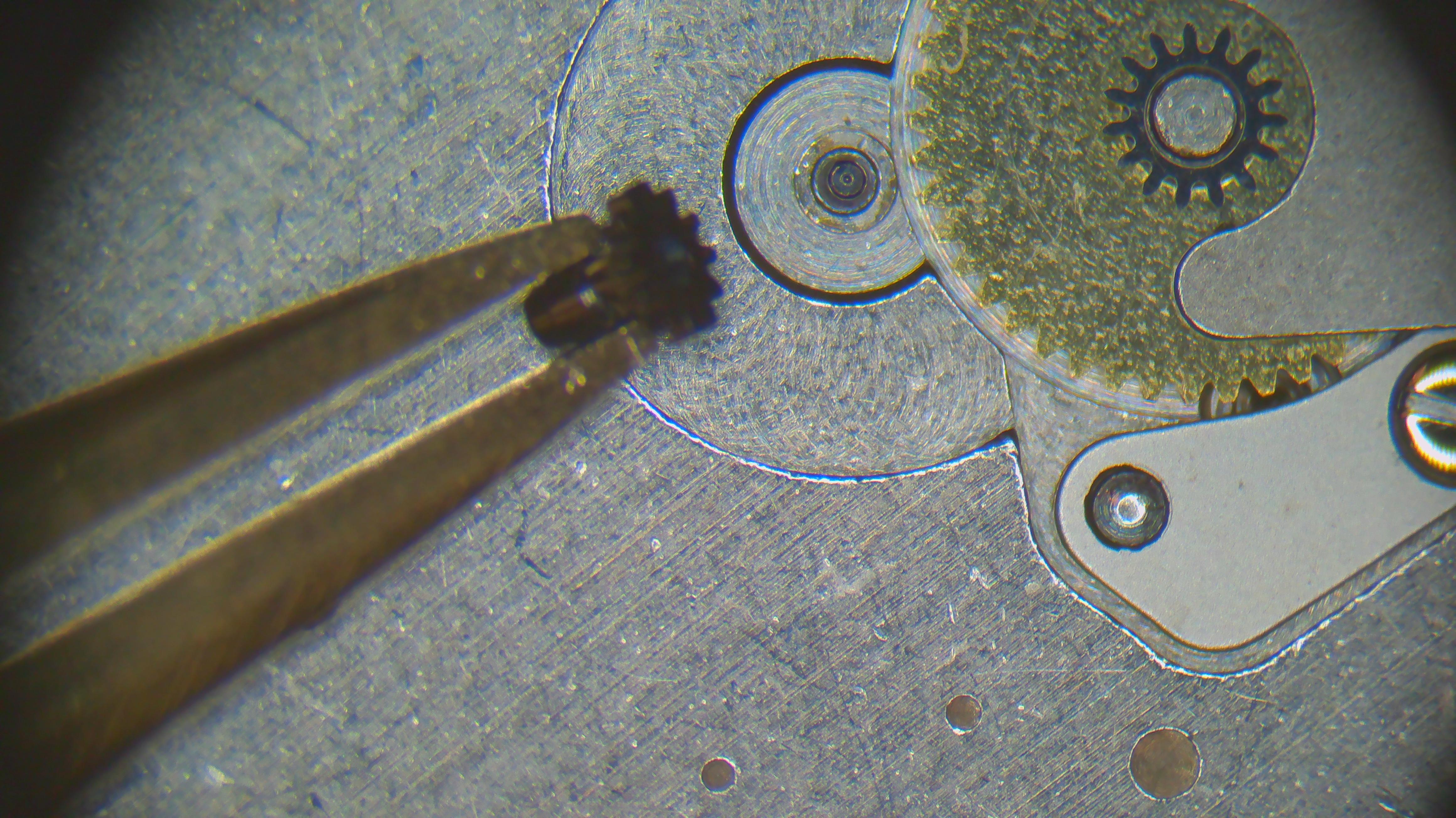
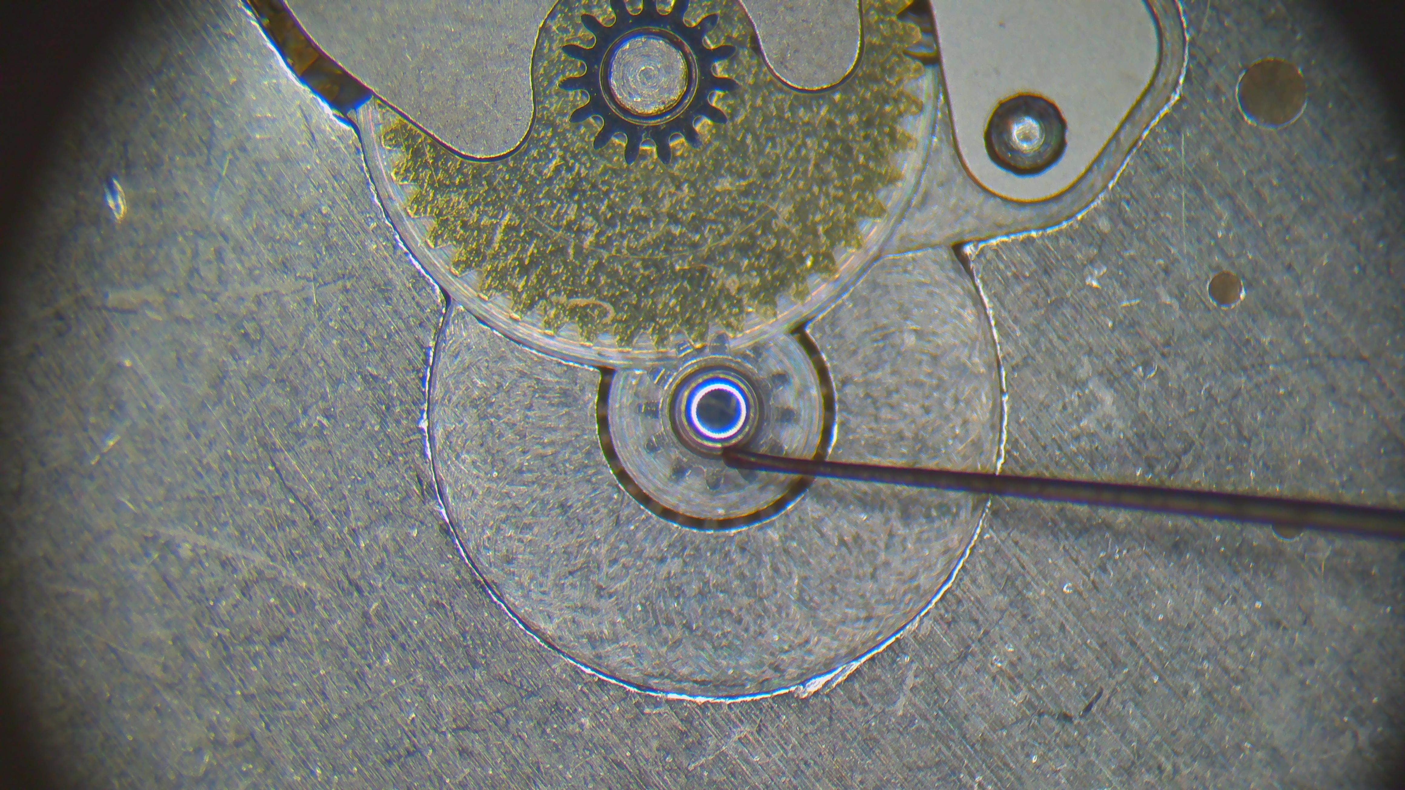
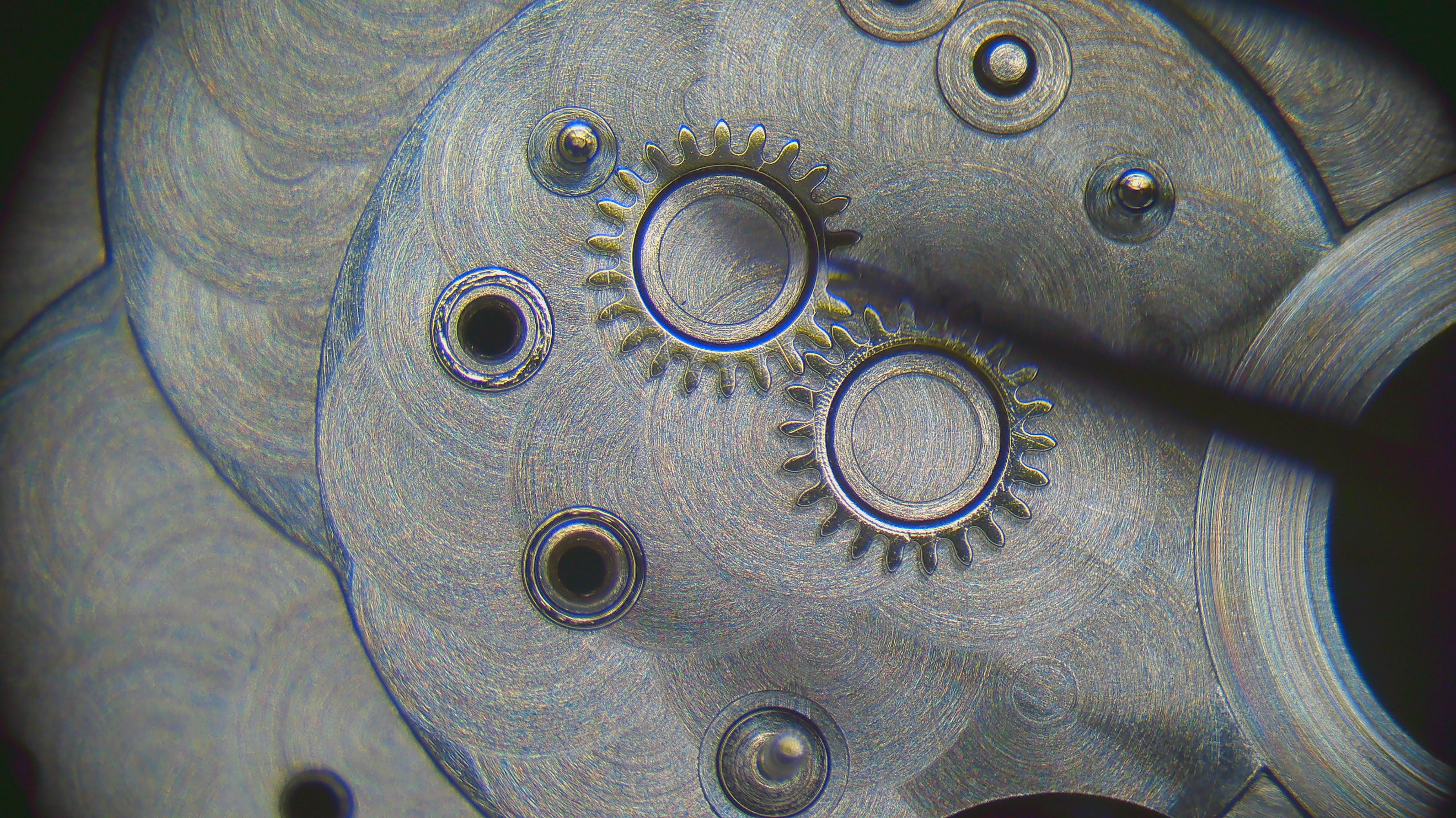
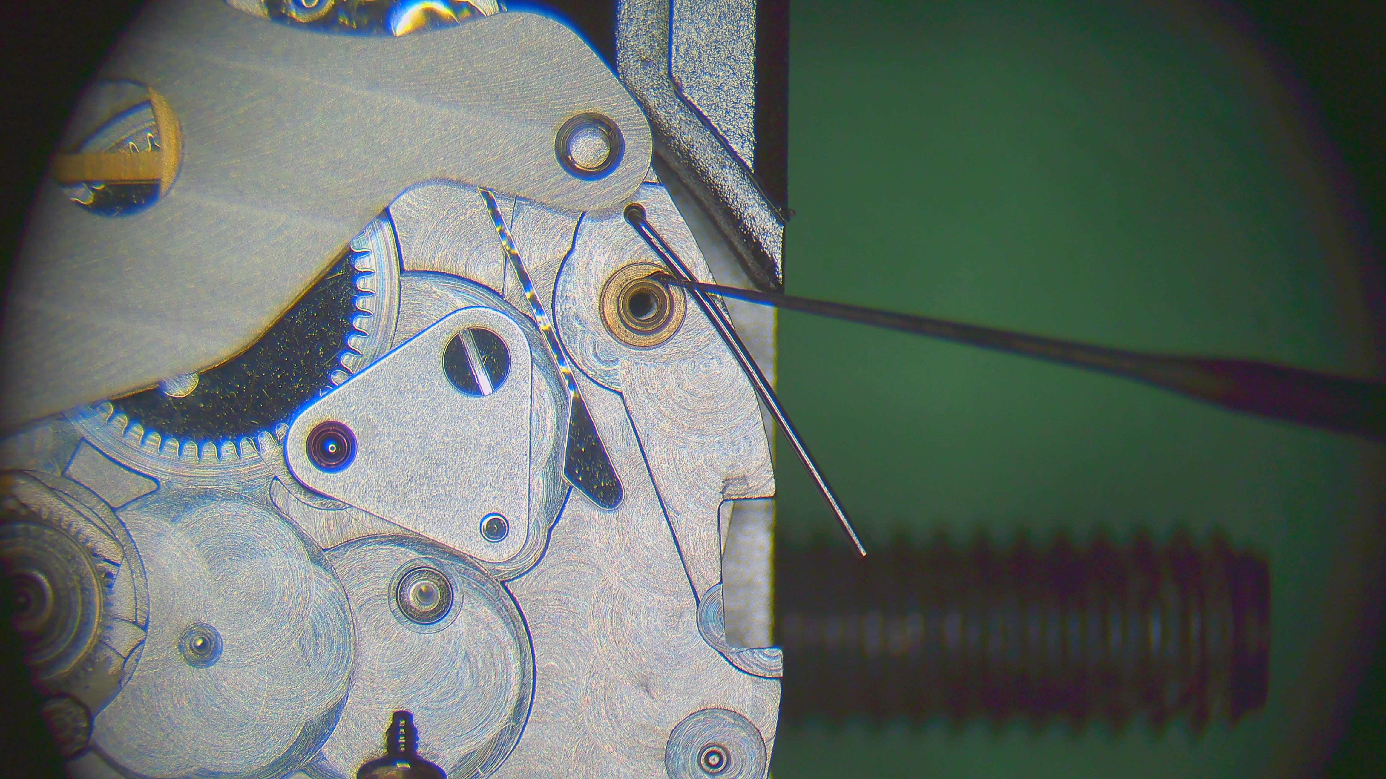
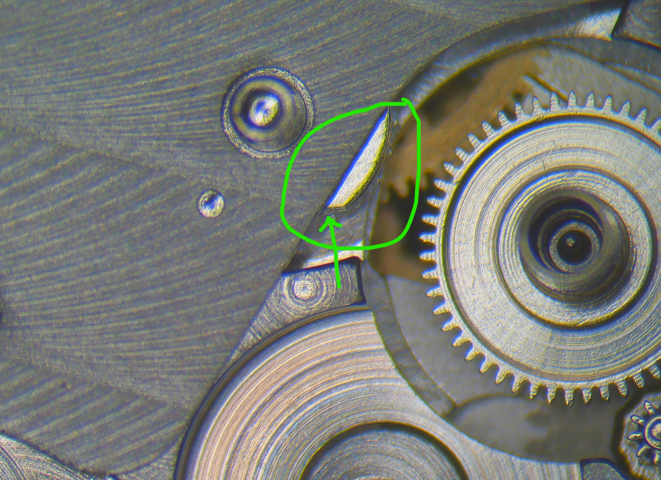
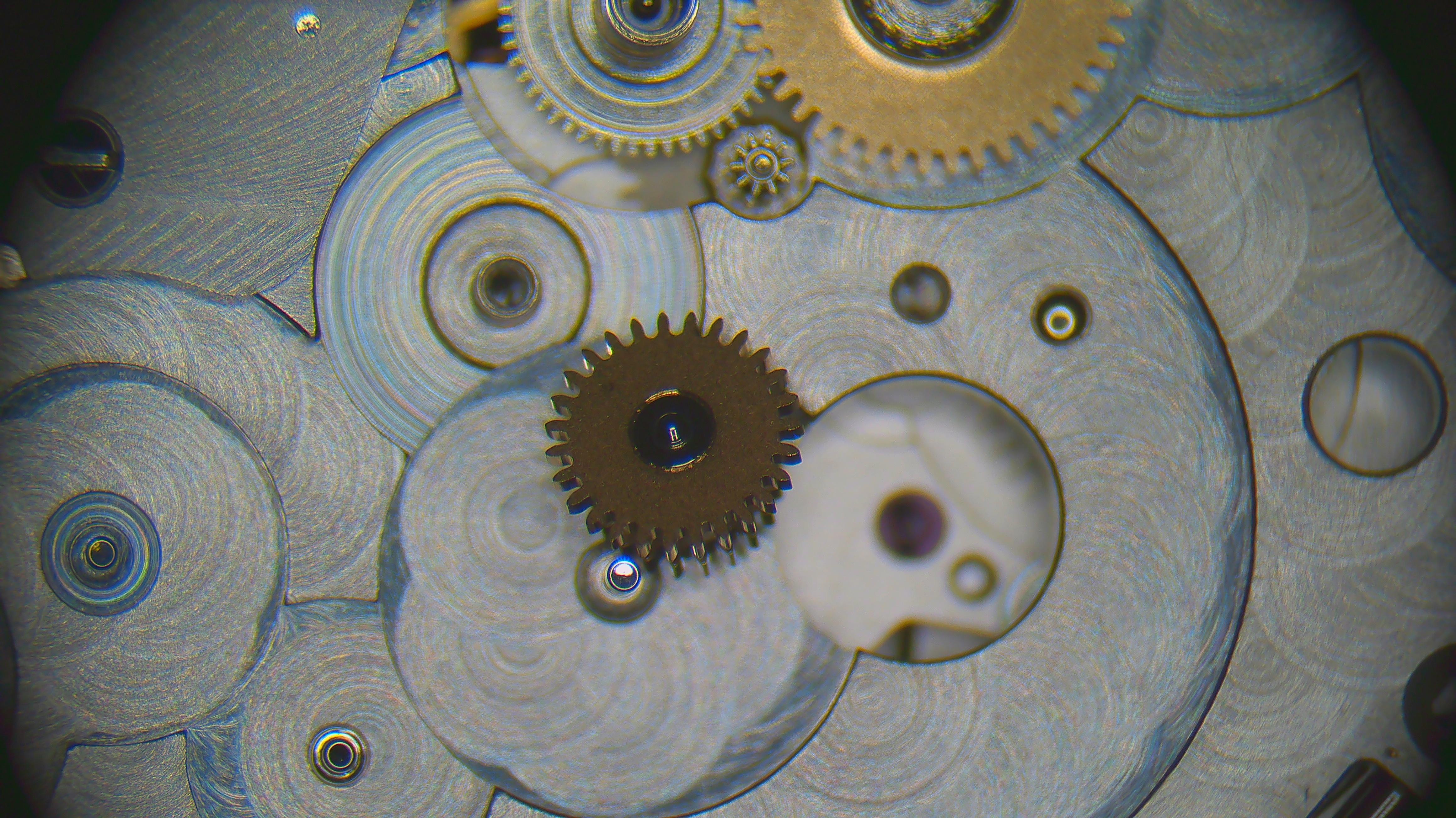
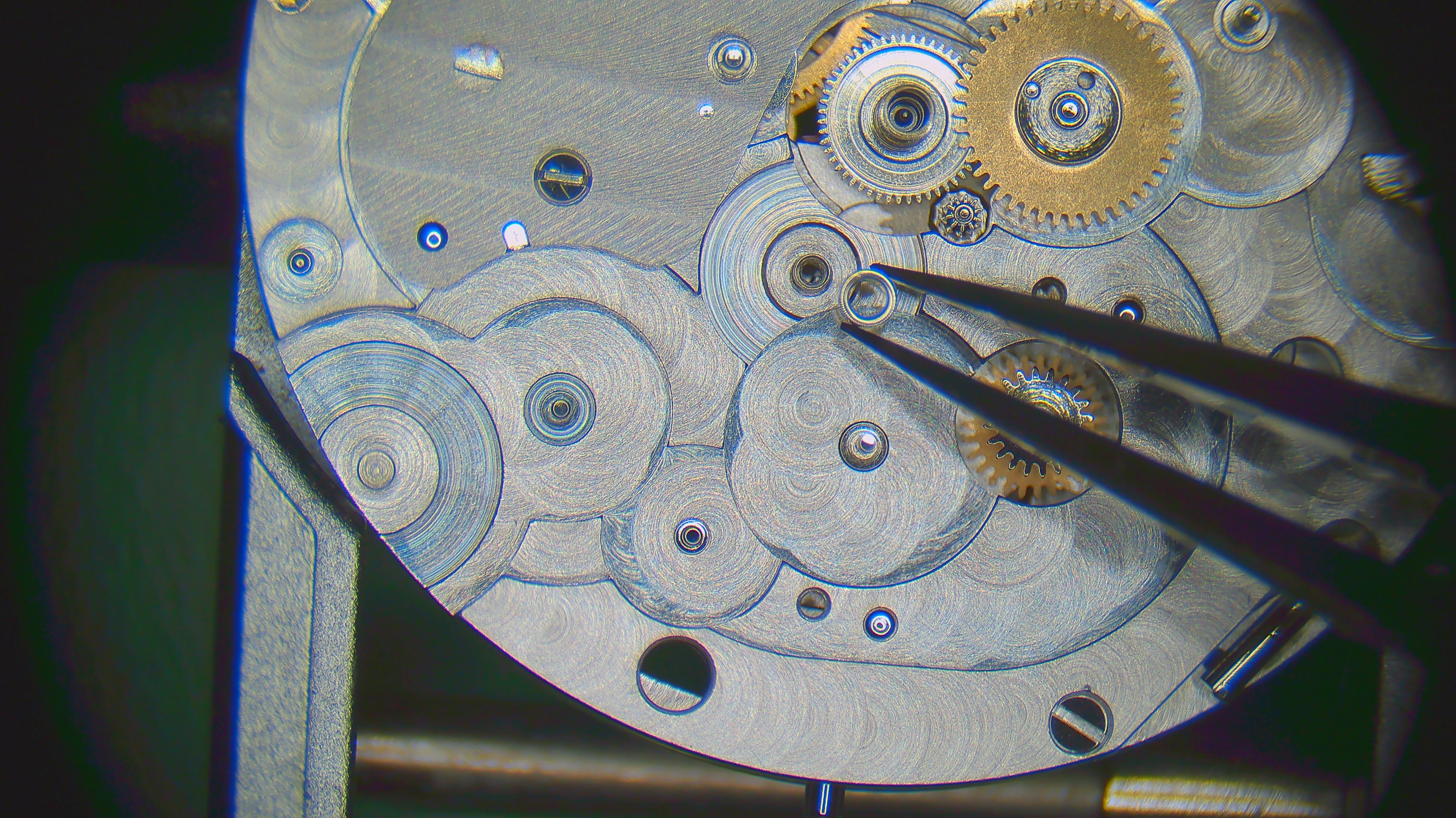
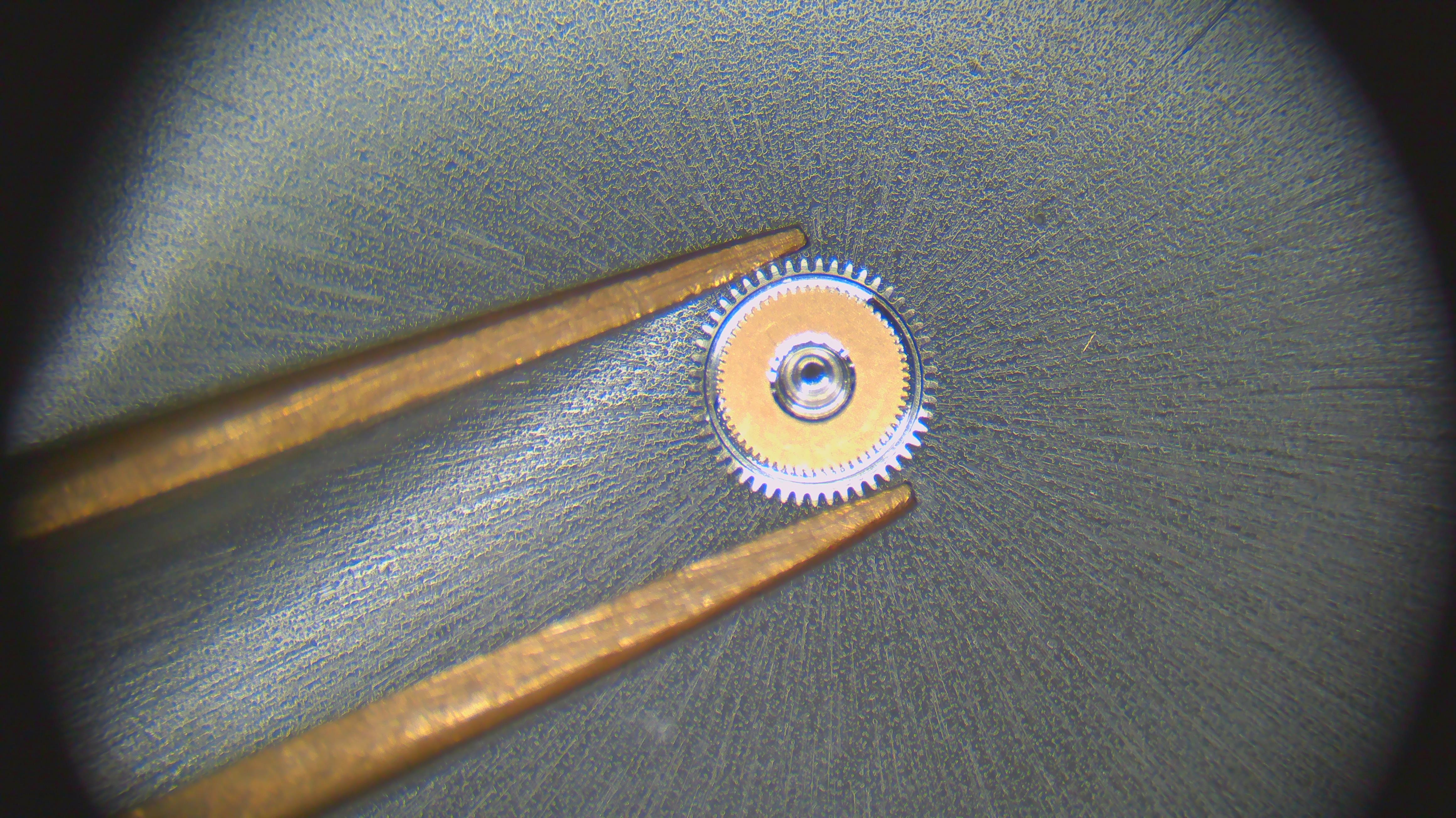
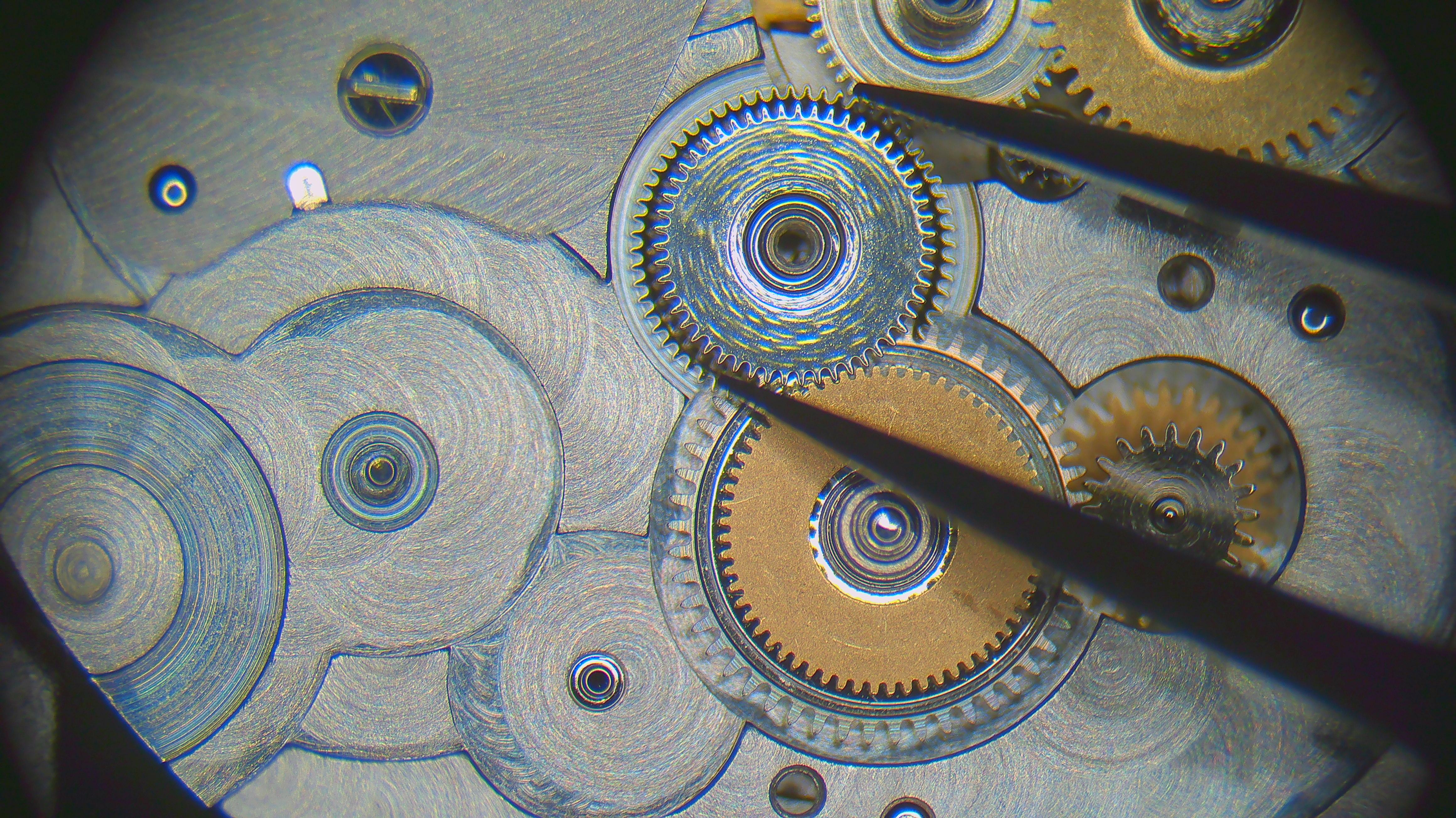
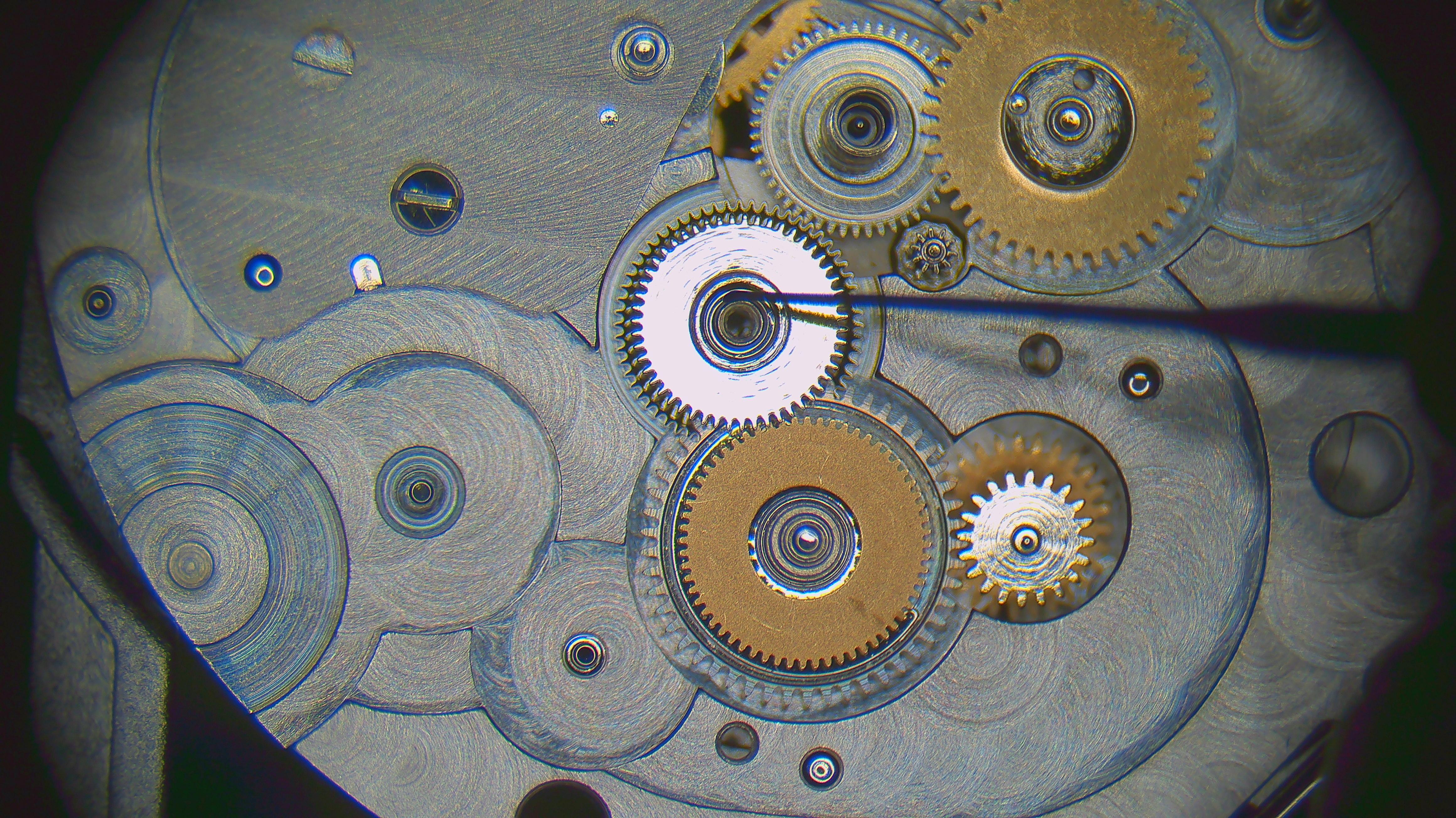
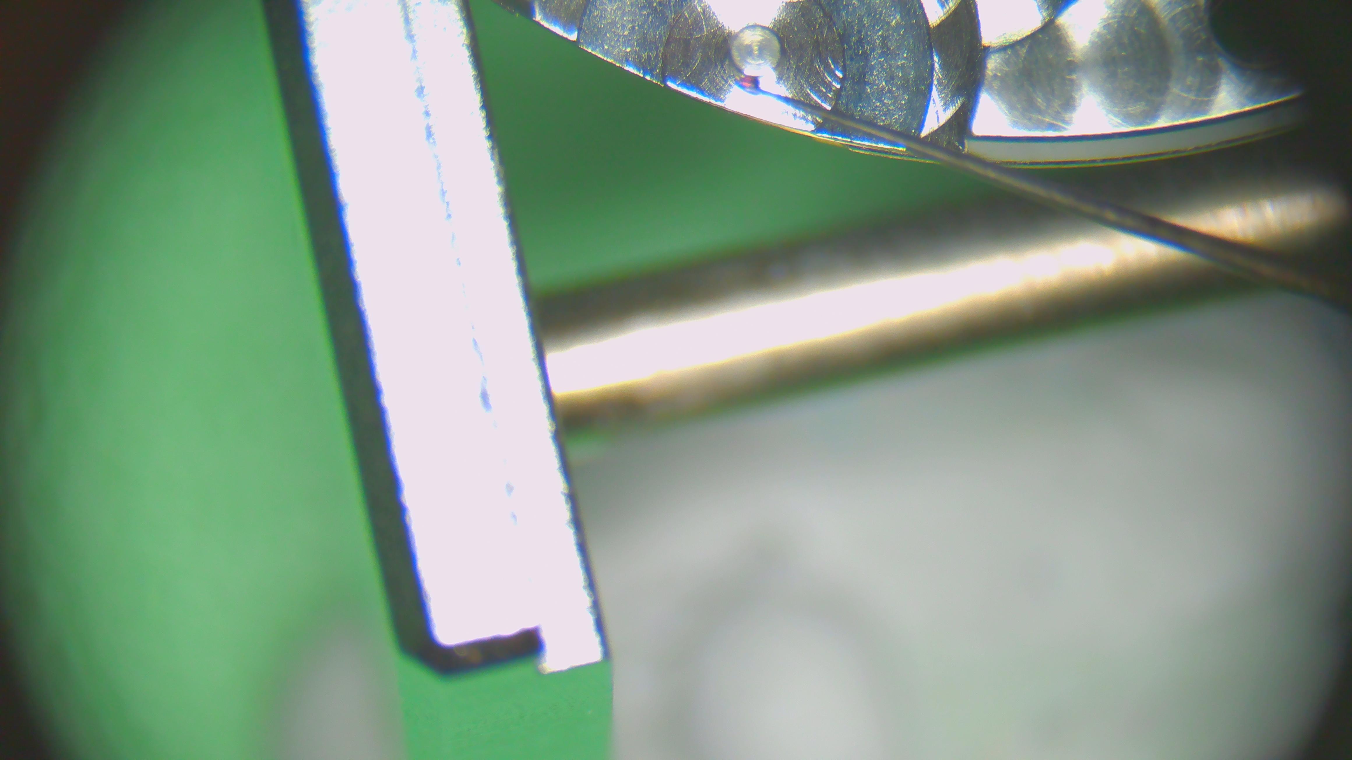
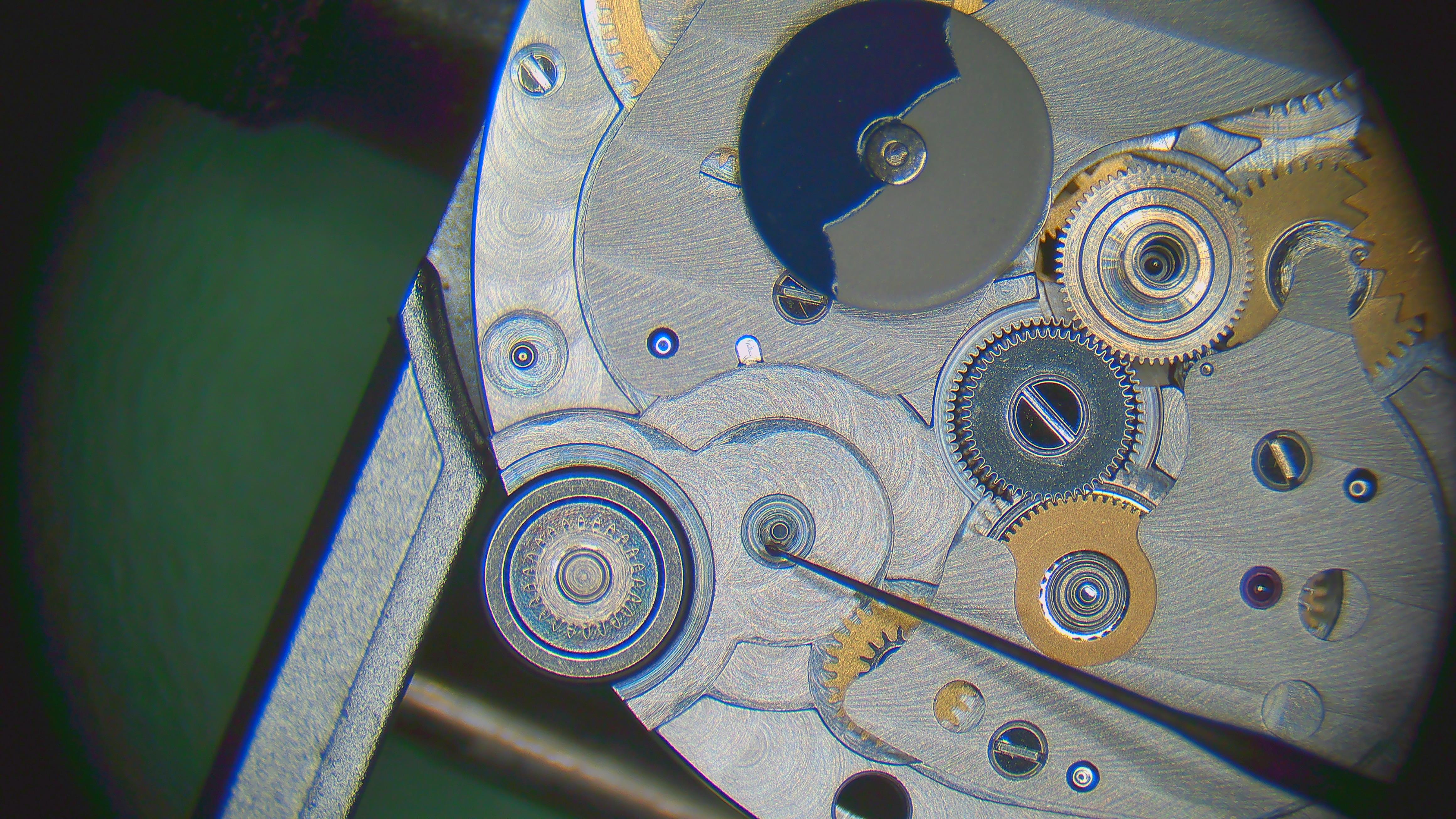
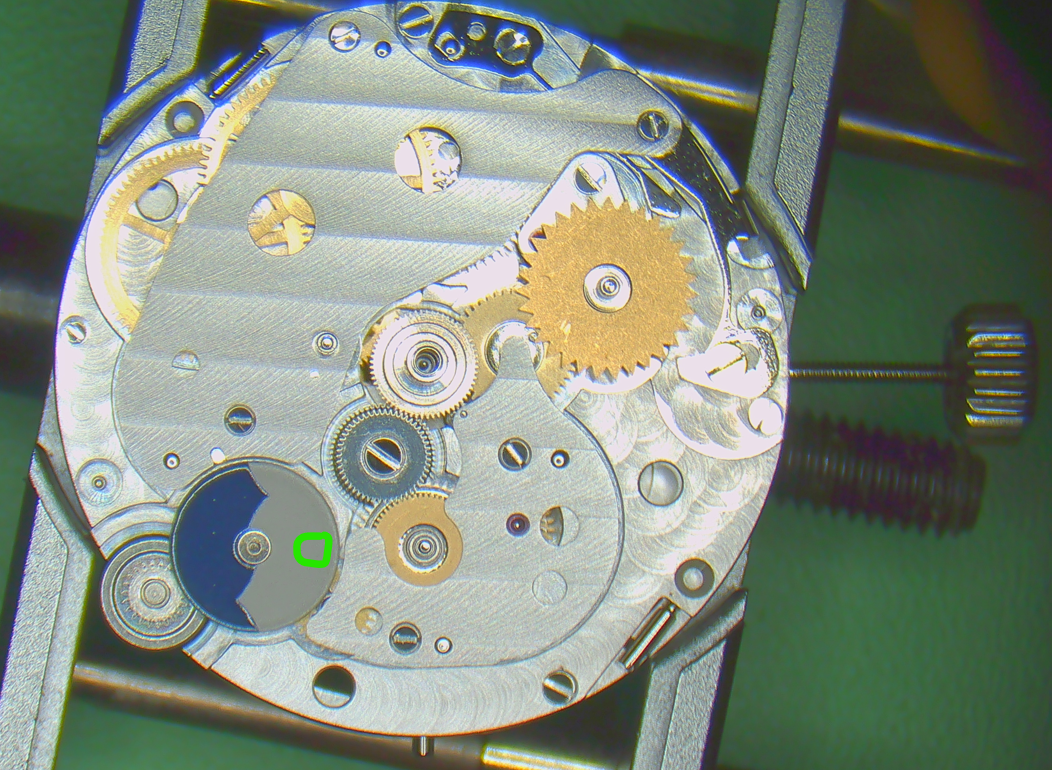
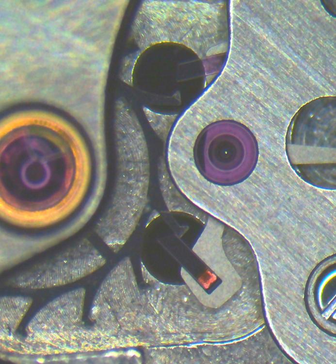
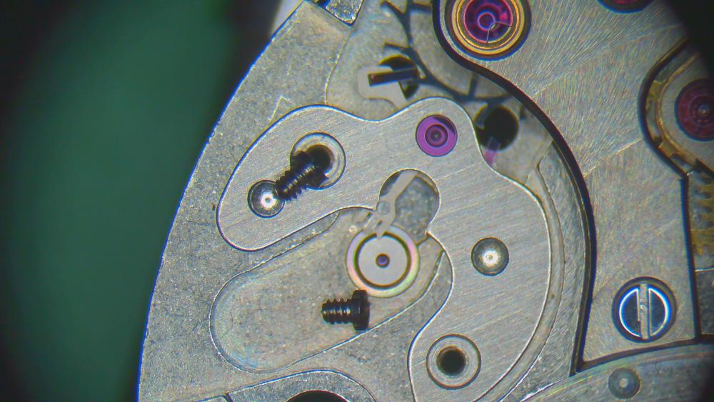
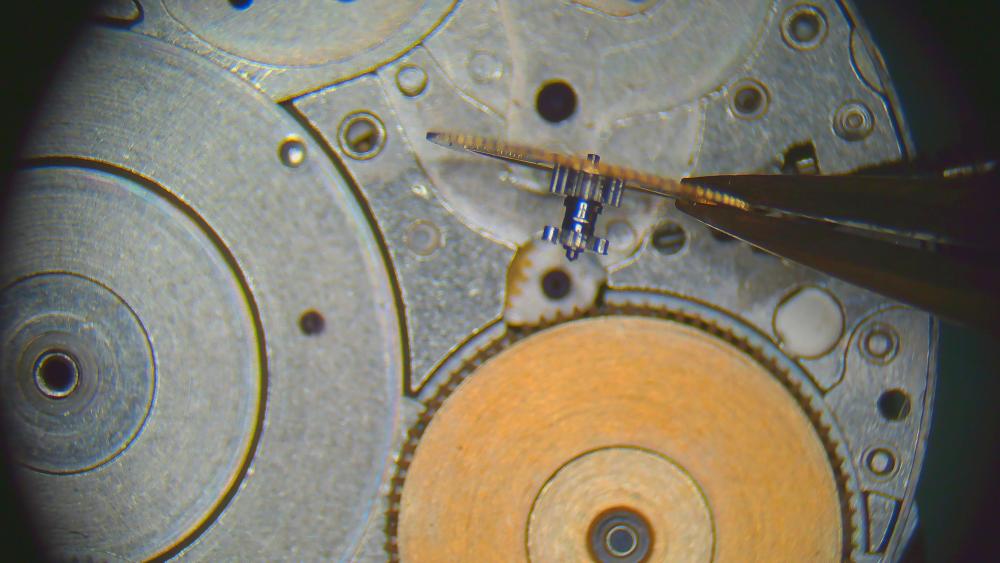
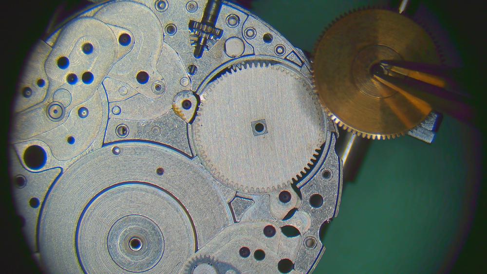
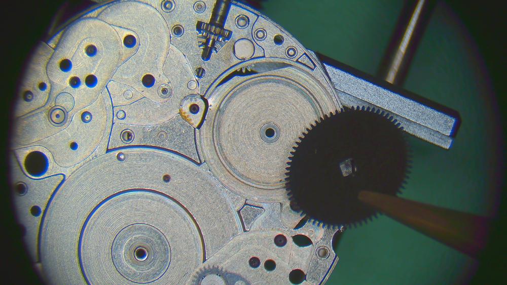
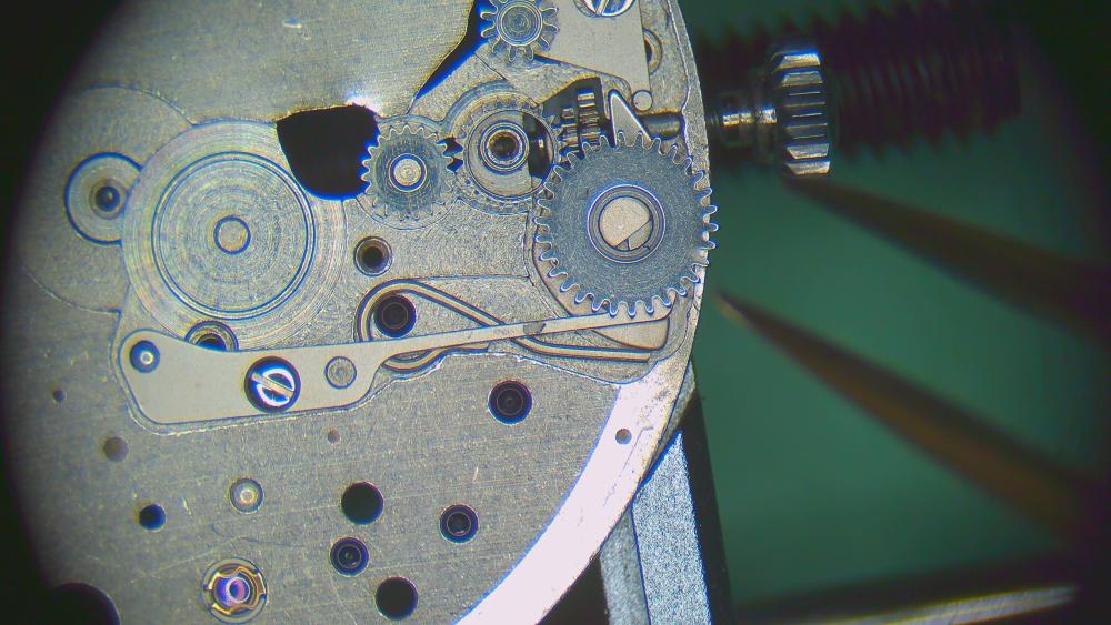
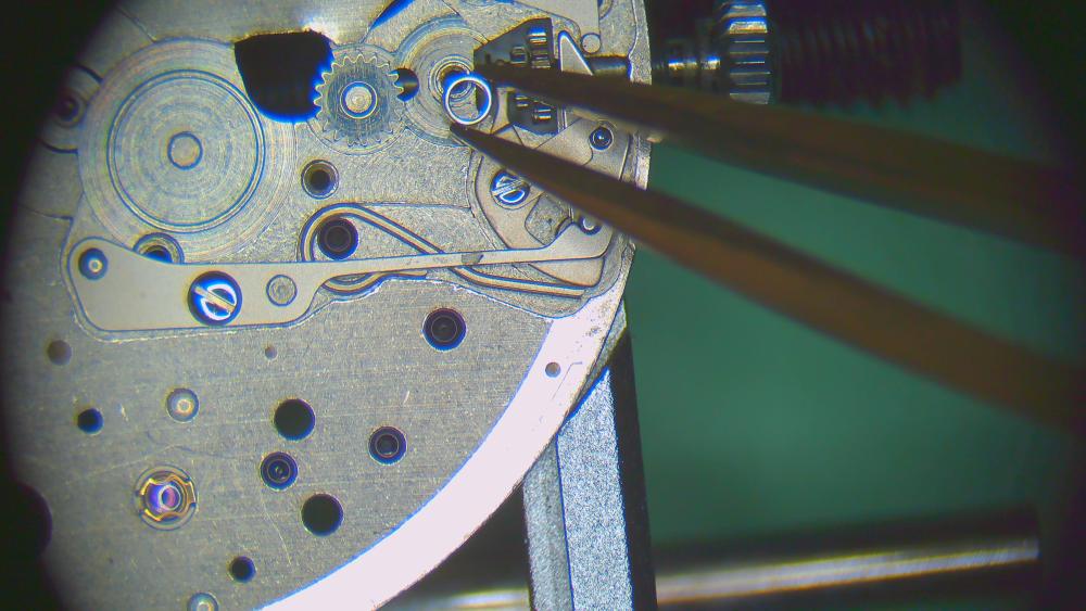
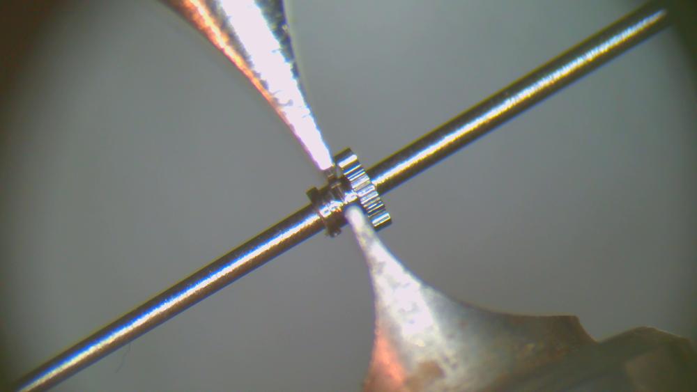
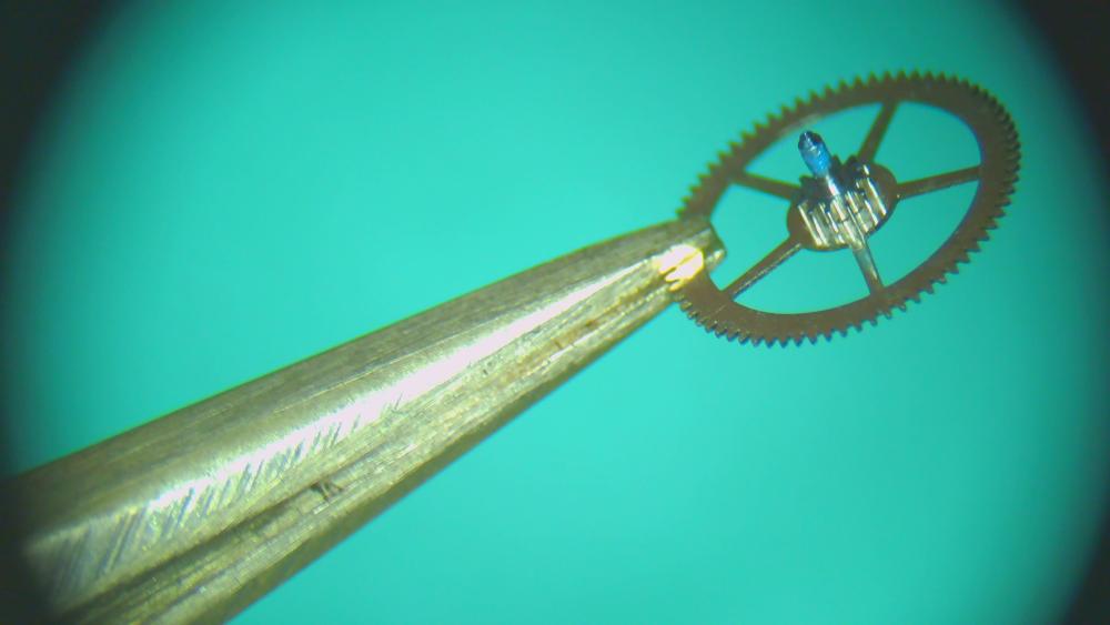
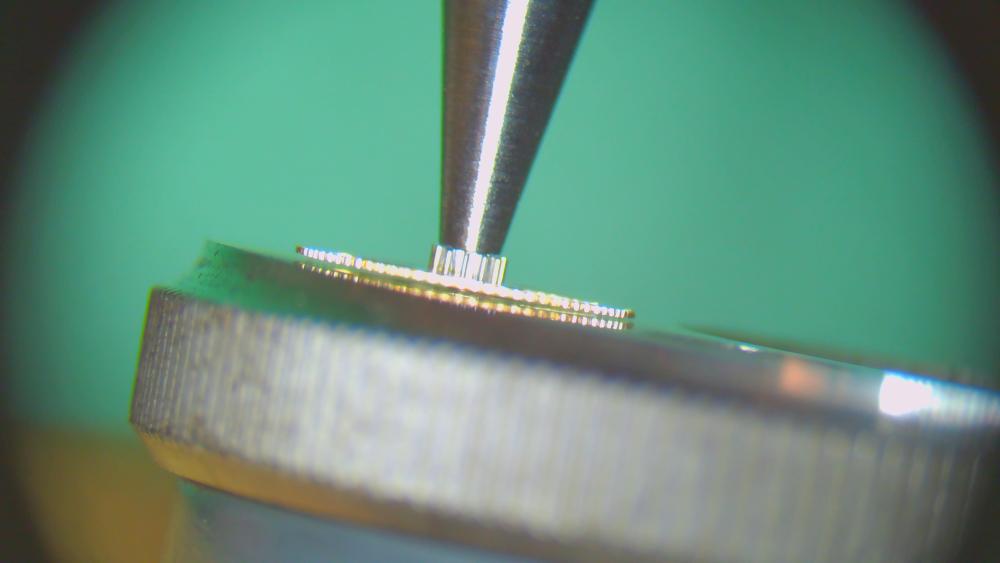
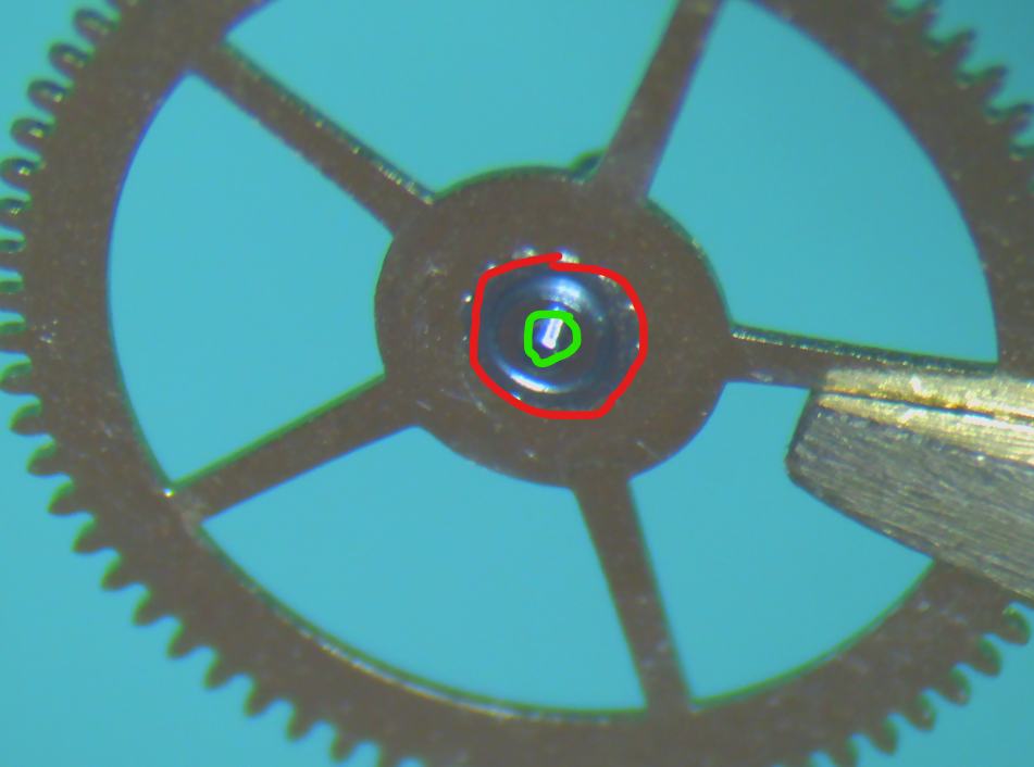
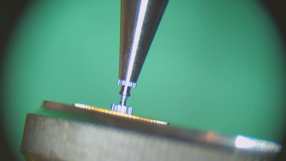
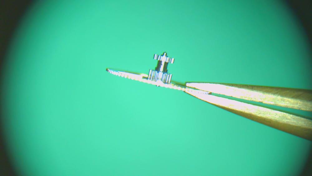
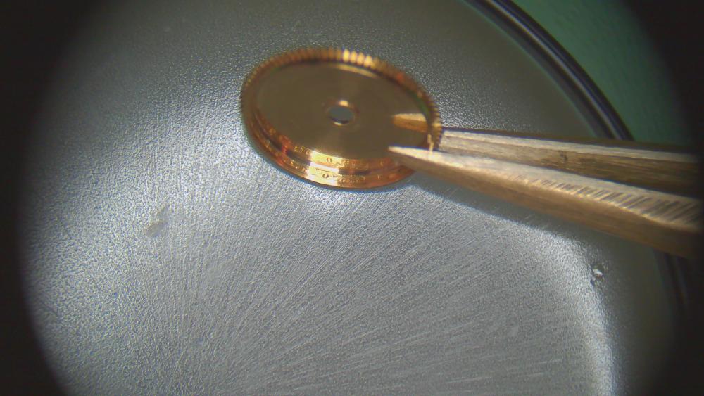
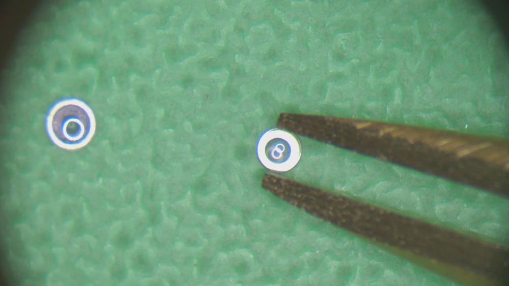
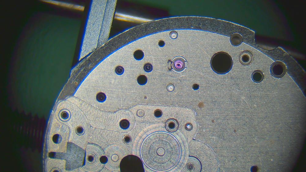
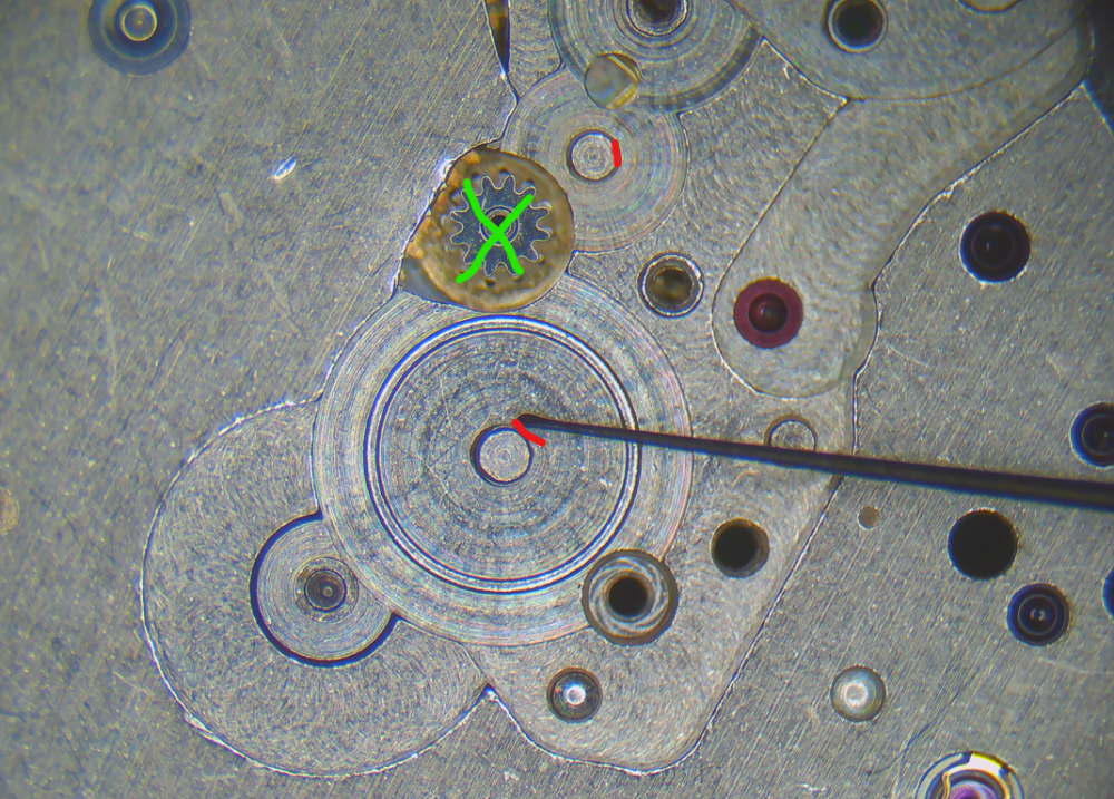
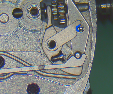
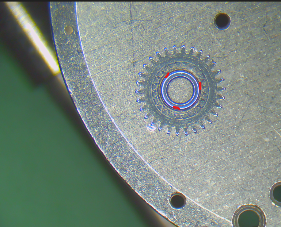
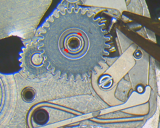
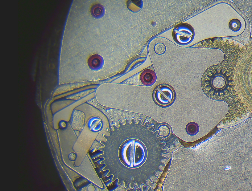
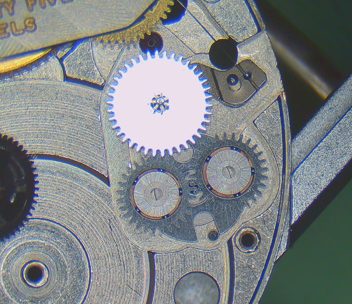
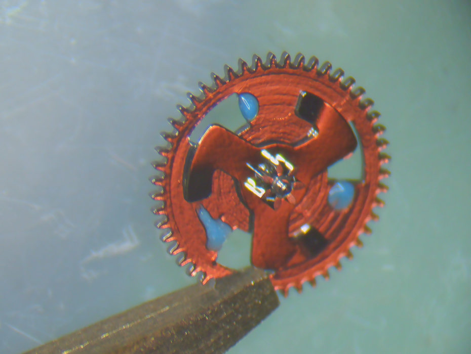
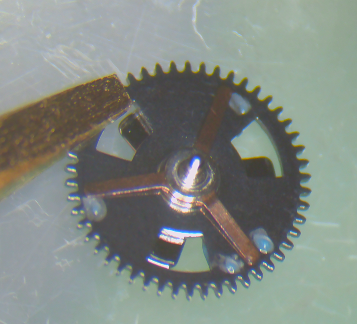
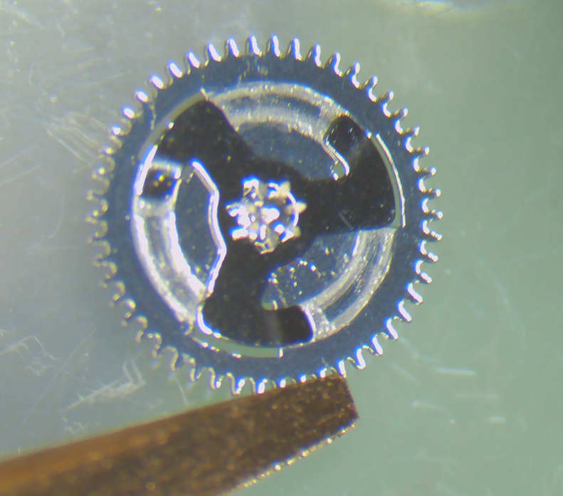
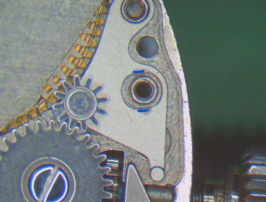
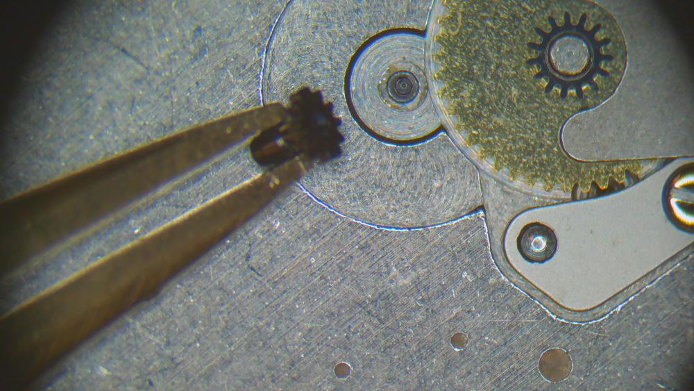
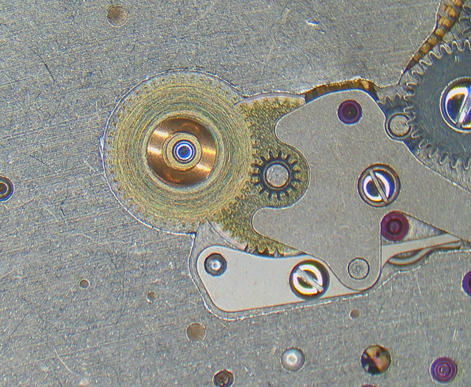
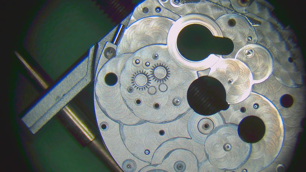
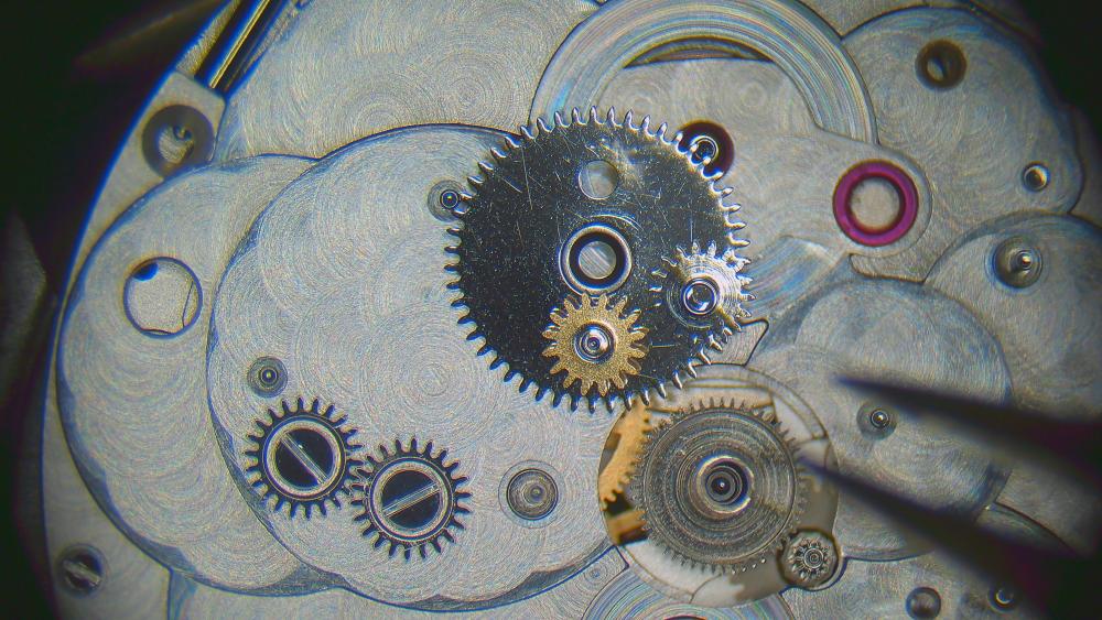
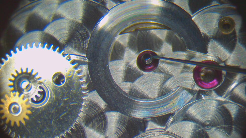
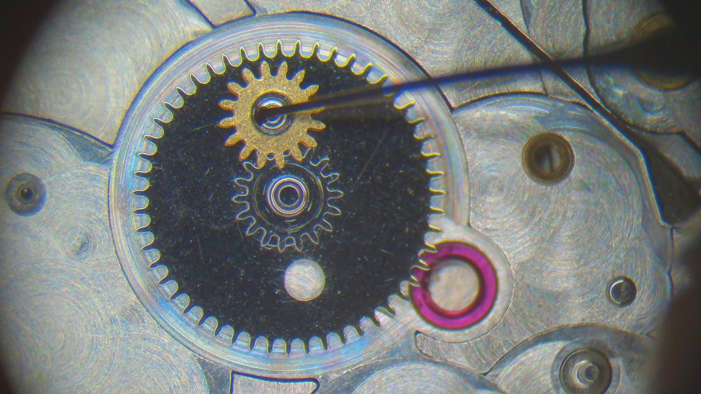
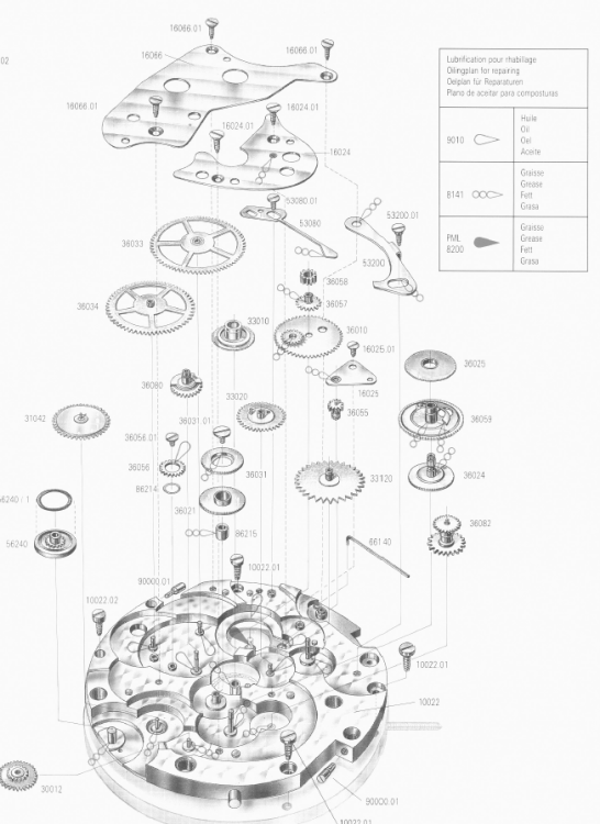
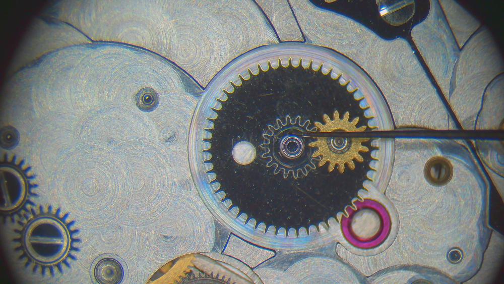
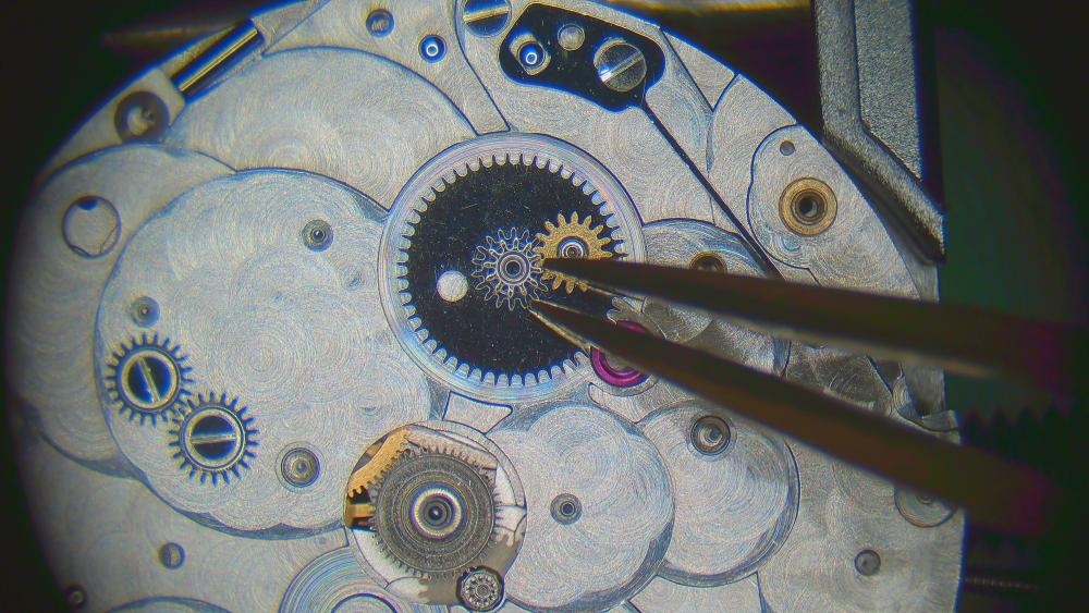
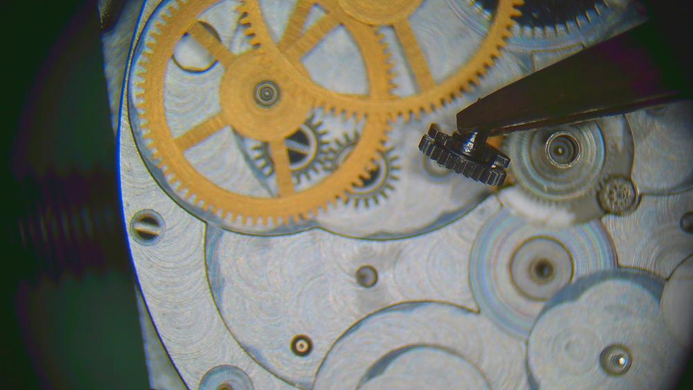
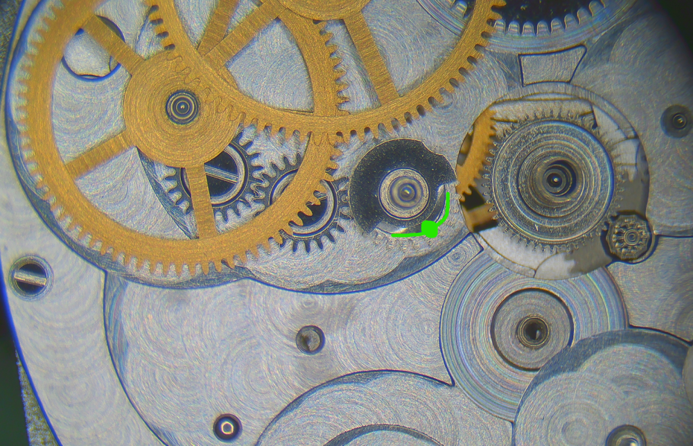
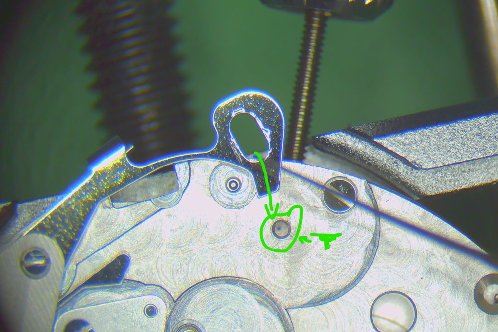
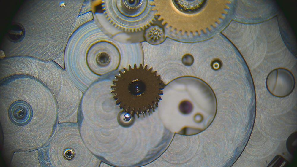
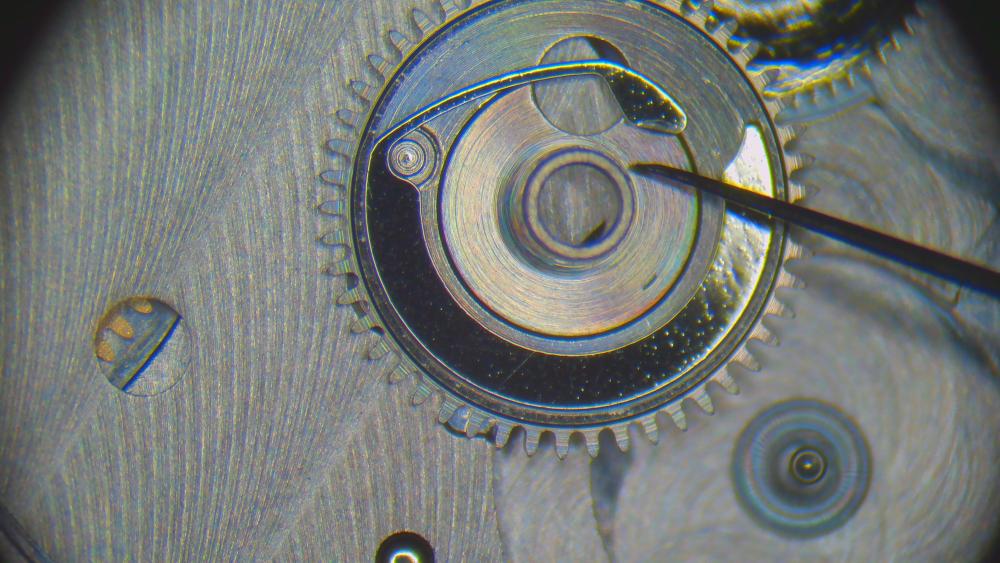
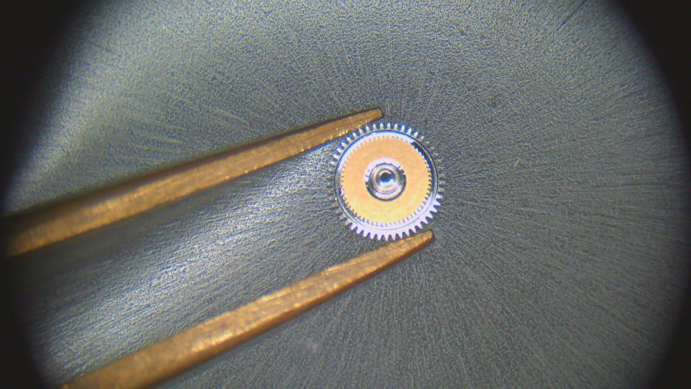
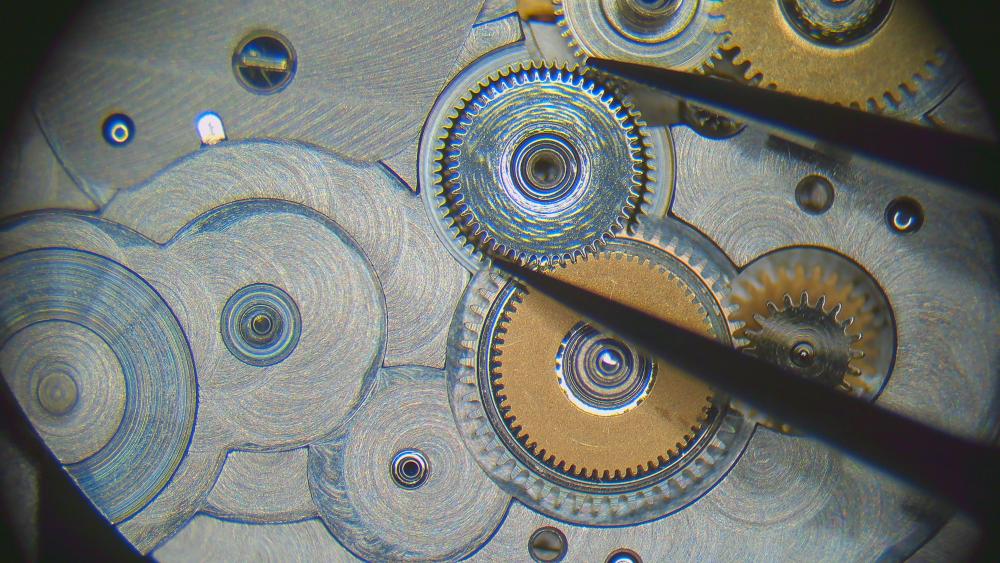
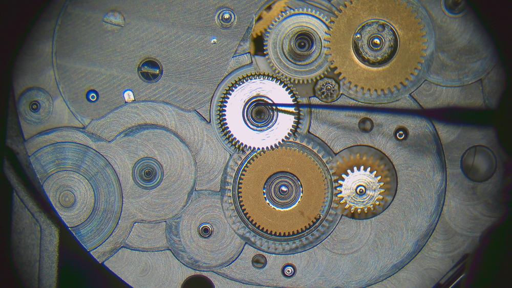
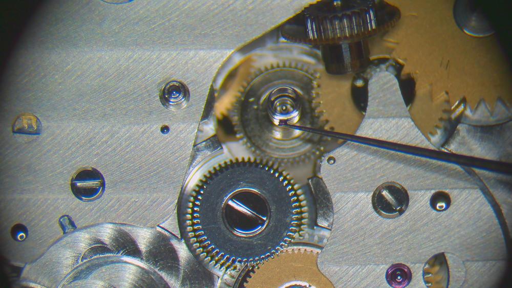
Ok, next one! First, the cannon pinion! Remember, this is the decentralized cannon pinion with integrated cannon pinion (and it goes where the green arrow indicates): First challenge: how to disassemble!? - do not use a Presto tool with its "feet" against the spokes/rim of the wheel! It'll bend the wheel. - using a scalpel or razor blade to slide between wheel and cannon pinion is also not working well --> I cut a triangular wedge into a spare barrel lid (of course, any other thin sheet of metal will do). Then I slide it between the two steel pinions, like so: Now I can use a presto tool to lift off the cannon pinion. Make sure the wedge is properly between the two steel pinions! No force should be on the brass wheel. Clean. In my case, the cannon pinion needed some tightening: Grease the staff of the (decentralized) centre wheel. I used 9504. To combined the two parts again, on the staking set, make sure the top punch fits over the whole staff of the centre wheel. It'll protrude from the cannon pinion and you don't want to punch on the staff.. Secondly, note that the wheel seems to "hover" over the staking block. You want to chose a hole on the staking block that just fits the green circle here, and NOT the red one (if you do the latter, you may punch out the staff from the wheel...) Push. Done. Now over to the barrel assembly. I distribute a thin layer of breaking grease around the barrel wall (I used 8217) New spring in (this is 0.70 x 0.1025 x 375, item number 266771 at CousinsUK) remember that the square part of the arbor points upwards close lid. then I oil with HP1300. Epilame treatment of pallet stones... ...and escape wheel (full submersion and then removing epilame again from the pivots) I take advantage of the balance still being installed on the movement (from cleaning) to oil the balance jewels on both sides of the movement. Just two pictures. It should be clear otherwise. 9010, of course. Now, disclaimer. Like in the assembly, I realized half-way through assembly, that another order would have been better. So I'll post the pictures in the order that I think is better. So please ignore the presence of some parts that were already installed in my less efficient, actual assembly process. I suggest starting with the keyless works before installing barrel bridge, train and automatic works. Why? The "decentralized" centre wheel and cannon pinion is held on the keyless side by a jewel in the cover plate for the keyless works. If you don't have that installed first, it's making the installation of the barrel bridge a bit tricky. So, first the pictures of the keyless works assembly. HP1300 on the posts (ignore presence of centre wheel here) add respective wheels and the seat for the other post place the pinions/wheels for the winding stem setting lever with some 9504 setting lever and stem replaced and adding some more 9504 (I spread this amount around by turning the stem while holding the oiler there) placing the yoke, adding some 9504 on the sliding points (excess will be removed later with rodico) and then the yoke spring unfortunately, I forgot to take pictures of the next steps, so I'm borrowing pics from disassembly. set lever jumper with 9504 as indicated and a bit of 9504 here combine the two parts of the crown wheel and the winding wheel and add HP1300 between them as indicated then add HP1300 on the seat and install them install the cover plate turn movement over add the tiniest amount of HP1300 to this rim (or don't, but don't let it flow over) combine ratchet wheel and barrel and replace them jointly (to get ratchet wheel into the right spot immediately and not smear the oil on the aforementioned rim). HP1300 on the arbor pivot as indicated. place wheels and then the bridge now the train wheels the 2-66 movement has this unusual fixed cap jewel for the escape wheel. I oil it from below and push the 9010 through with a sharpened oiler. Inspect size and position of oil circle from the top side. install train bridge I choose to proceed with the automatic works now first the secondary click (for auto winding intermediate driving wheel). the tiny spring needs to go through a small hole where indicated view from the other side of the movement place the intermediate winding wheel now there's this special wheel which which disengages the automatic works when the watch is wound automatically (same as JLC 889 that I serviced recently). The slipping "arms" need some grease (or oil). I used 9504 I then spread it around by gently moving the arms around (clockwise in below picture) place the wheel and install bridge I decided to use HP1300 on all these pivots (escape wheel pivot was oiled previously with 9010). I prefer the higher viscosity oils to avoid any creeping. Happy to drop a few degrees of amplitude for that. turn movement over and install primary click at the ratchet wheel very light use of HP1300 (sorry, screw not pictured) now back to the keyless works again small amount of HP1300 tiny bit of grease as indicated secure with screw and place spring (careful with this one.... it's a highly qualified candidate for the Swiss space programme) arm the spring and secure with screw dial side oiling with HP1300 (red) for everything except the escape wheel (9010, blue) I add a tiny bit of 9504 to the click/teeth here turn over again. pallet fork. as usual, I install the balance, let it run a few minutes. remove the balance. oil the exit pallet stone with 9415. one small drop every 4-5 teeth. then the rotor. NOTE: I didn't oil any of the four ball bearings! This is up to debate.... in some service manuals across different brands, ball bearings are oiled (with 9010 or Lubeta V106 or 9415), in other manuals they aren't. I chose to not oil because the watch case is barely dust-proof. And if any dust gets inside, it'll attract to oil. If it gets on the ball bearings, it'll quickly clog up. But happy to receive other opinions. and the complete train side then back to dial side again. Oiling the inside of the "false" cannon pinion with HP1300. then the outside with HP1300 and place hour wheel and dial washer a bit of regulating. Note from disassembly that the pallet stones lock was a bit excessive. The amplitude could probably be increased by moving them inwards a bit. But I'm happy with this result as it is and will let it be. Since I haven't done pallet stone manipulation yet, I don't want to practice on a movement where spare parts are extremely rare and expensive (the company has been out of business for about 50 years). dial (two screws) and hands on That's my new baby!


 1 point
 -
@JohnR725 having spent most of my working life in IT I can understand what you mean about garbage in - garbage out (gigo). I can figure out what you’re trying to get across to us on here John, I just find it hilarious when the technology does things like in one of your posts above replacing “horn” with “porn”, not once but twice. i you think you have it bad with voice recognition, I’m Scottish! Thank you for all you do here Tom1 point
-
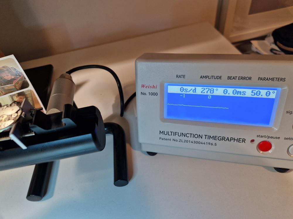
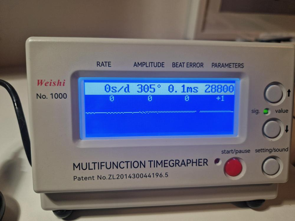
Ha - I woke up to find I have an entire textbook to read on this thread. Right - The lift angle changed, and the timegrapher needs to be informed of the change. But the locking depth also changed (reduced in my case) which led to a more efficient impulse, which resulted in a real world amplitude gain of at least 25-35deg on the balance swing. Initially the timegrapher made it look more like a 40-50deg gain because it was not aware of the new lift angle. Two things happened, one of them matters to the performance of the watch and the other only matters to please the Weishi. This might have been in a PM with John rather than back in the thread but a few days ago he told me about: ...and I ran that test to find that the outer banking pin was noticeably farther off the balance jewel center than the inner one. The exit stone also had a deep lock. So this is why I moved the outer banking pin a little closer to the balance jewel hole. The two pins are now closer to the same spacing either side of it, probably correcting someone's change from 70 years ago.1 point
-
You’re making sense to me Rich, like you I am learning and this stuff is interesting. I am grateful for the information @JohnR725 gives us and his immense patience with us. Although his dictation software sometimes do make I laff . the Jendritski book I was reading John is “the watch repairers manual “ I think it is the same as you mentioned, just without the word “Swiss “. I have a theory as to why there is a progression from adjustable/adjusting banking pins to today’s that are milled into the mainplate. When most of the watchmaking material we have learned From manufacturing tolerances were no where as tight as can be achieved today. There is an old saying in engineering, “if you can’t make it perfectly, make it adjustable “. So now my theory is that as the tolerances of milling the mainplate have reduced they are now at the point they can be considered negligible compared to the end/side shake tolerances that are required for the pivots to function correctly. Previously part of adjustment of an escapement would be a larger part of the manufacturing process because of tolerances just to get the watch to work. If as Rich hypothesis the lift angle being used in timing machines is to be used to calculate the amplitude we have an inherent potential for error in that we look up the designed lift angle and use that whereas the real lift angle could be something quite different. This conversation is both interesting and thought provoking, always good in my book. I’m starting to get the idea, I think, of there is only one magic amplitude number when looking at a watches timekeeping not 270 degrees as a minimum but more like 220 degrees after 24 hours running would be closer to an ideal so that during the running time of the watch balance poise errors are minimised. as in all engineering there is a theoretical world and real world that a machine/system has to work in. Not having been immersed thoroughly in the theory and practice of horology it is sometimes too easy to latch onto something that has been read or heard that maybe tends more towards either theory or an old wives tale. Tom1 point
-
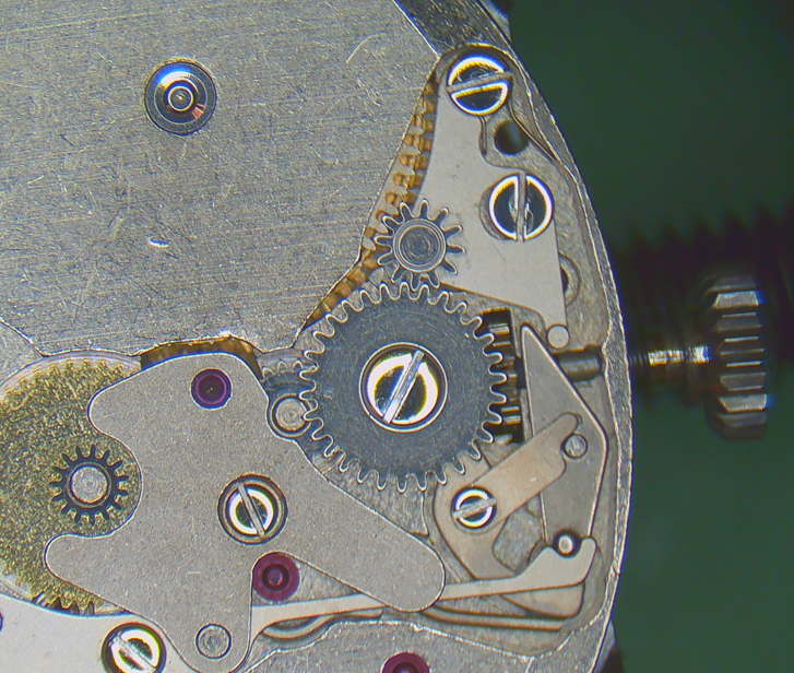
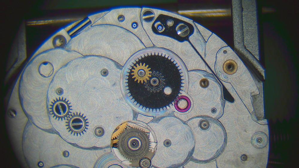
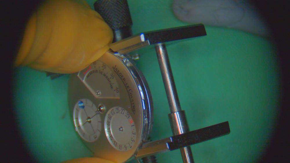
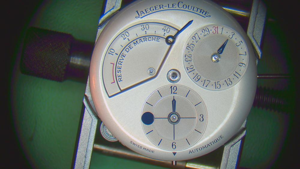
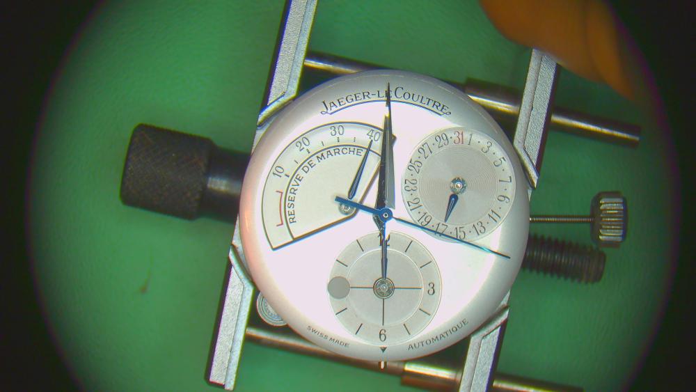
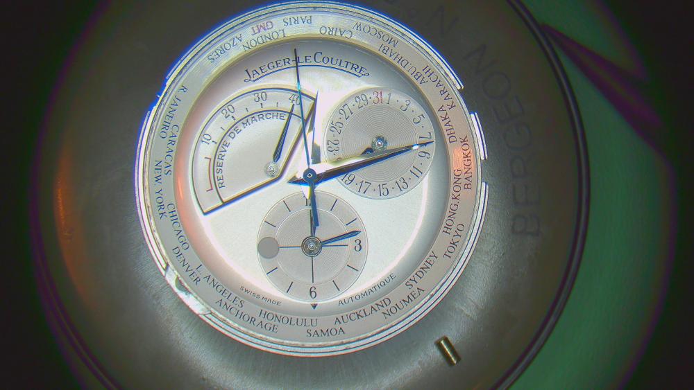
FINALLY, the complication module: - power reserve - date - second time zone with day/night indicator and city ring Here is the oiling chart and overview: NOTE: I decided to use HP1300 wherever 8141 and 9010 were recommended. Also used 9504 instead of HP1300/8141 in some places (see below). 9504 instead of 8200. I randomly start with these two wheels that are identical. But watch out, the seats are tapered, so they have a top and a bottom side. Don't force down if it doesn't fit easily. [Note: I installed these wheels before installing the complication plate on the movement, but of course, they can/should be installed when the module is on the base movement] seats installed wheels and oiling with HP1300 Complication plate installed on base movement. Three mid-sized screws on bottom, right and top. One smaller screw on the left. Next, for the power reserve is this set of wheels. They are installed on the extended barrel arbor to trace the level of winding. They are friction fit (with 9504) and the fit is quite "soft" in order to slip easily when the barrel is fully wound (the power reserve indicator can't/shouldn't move beyond 40h, but the barrel arbor will keep turning when wound further by the automatic mechanism or manual winding) Grease the bottom half (!) of the arbor position the small wheel over the hole of the large wheel. push onto the arbor, e.g. with hand fitting pusher oil the satellite wheel with HP1300 upper half of the arbor gets HP1300 another wheel on top carefully oiling the jewel for this pinion (green arrow). This pinion connects to the barrel itself and lets down the power reserve indicator. A bridge just for the pinion. Oiling with HP1300. HP1300 for the posts of the two large reduction wheels Then this special wheel (post oiled with HP1300) position the wheel more or less like this. The cover palate for these wheels has a little pin which will go into the open area of that snail-like top-part of the wheel (indicated in green). The hand for the power reserve indicator will go onto this wheel. Then the watch is fully wound, the pin on the cover plate will stop the wheel from moving further (the wheel on the barrel arbor will start to slip). Again, careful when placing the cover plate for these wheels. If the pin doesn't go into the cut-out of the wheel (green marking), you may bend the cover plate. Before placing the cover, plate, I also have to position the spring and lever for the date corrector pusher. It's a bit fiddly and falls off easily. first the spring HP1300 on the post the lever. Just balance the spring and lever in this position and install the cover plate. AFTER the cover plate is installed, oil or grease here (I use HP1300) Tension the spring/lever and install the screw (sorry, not pictured). Now, I'm testing the power reserve by fully winding until the special wheel is stopped by the pin under the cover plate. This is the position of it when it stops (small indent just a bit visible): Now to the second time zone: Oiling the bottom pivot of this wheel with HP1300. This wheel connects to the keyless works (when the stem is pulled out the the middle position, see earlier post on keyless works) and allow the setting of the second time zone (meaning: change the hour in the second time zone for a given city/time zone) A seat here HP1300 on the outside of the seat/post This wheel now (which basically copies the time from the home time to the second time zone) oiling post with HP1300 placing the wheel greasing the click within this wheel. This click ensures that the second time zone hour hand can only be set in full-hour increments. oil the seat/post inside the wheel with HP1300 I ended up removing the wheel again to place the inside wheel and ensure that the click engages properly (and that the combined wheels are "flat") then I replace it again as a unit, followed by the next wheel (held by the tweezers in this picture) And oil the post again with HP1300. the wheels are then secured with a screw (not pictured). Another post with HP1300 and the wheel in the picture (this will, via another wheel, connect to the second crown to allow changing the time zone) the cover plate for the second time zone mechanism HP1300 for this pivot now the DATE (easy peasy). Post with HP1300. date wheel. position the spring. A bit of grease on some of the teeth. testing the corrector and spreading the grease. clean off excess grease after a round. oiling with HP1300 and placing the hour wheel HP1300 for this last wheel that engages with the second crown for the time zone wheel placed (bottom left of picture) oil the post of the day/night disc with HP1300 ATTENTION: the placing of the day/night disc needs to correspond with the placing of the hour hand of the second time zone (i.e. if you place the hands at 12 noon/midnight, the disc needs to show the middle of day or night). This was a bit of trial and error.... unfortunately, I didn't take a picture of the final/good positioning of the disc, but here's my suggestion: 1. take 6am/6pm as the basis (remember to place the second time zone hour hand accordingly) 2. try to position the day/night disc in such a way that you see both blue and white approximately equally (i.e. day is coming or night is coming). The window on the dial is approximately where I drew the green circle in the picture (so the positioning on my picture is now for noon). 3. put the dial on an check. Correct disc, if necessary. [note that the below picture doesn't match the disc position on the previous picture] secure dial screws (2x) Hand setting: 1. set the second time zone hand according to the day/night disc position (e.g. as described above, if white and blue show to equal amounts, set to 6 o'clock). 2. set date hand to any date (make sure you are NOT within 10pm-2am because the hand will still be moving and you'll end up with a date hand that is off-target) 3. wind the watch fully and place the power reserve hand to 40 4. set time until the date pointed clicks over. Now place the remaining hands (including minute hand of second time zone. check hands carefully from the side, particularly to make sure that none of the hands in the recessed sub-dials are deep enough not to touch the main hour hand place the movement in the holding ring (quite easy because there's a positioning pin) and oil this post on the ring place this pinion (full leaves on top, 4-leaf to the bottom) place the city ring, but NOT like this! Ensure that a city is centrally aligned with the little arrow below the second time zone sub-dial. Using the M in GMT may be the easiest. But any city will do, just the middle of the word needs to align. Don't forget to re-insert the pin into the tube for the date corrector (above the crown) plenty of silicone grease into the crown place case on top, turn around, insert crown. Remember to loosen this screw before inserting the crown; and to tighten it again afterwards. secure the movement ring with two blued screws and two casing clamps+screws. Plus installing the rotor with 3 tiny screws. (note, these are 0.8mm screws with a relatively wide slot -- so dress the screwdriver accordingly) DONE!!! Tempted to scratch my name into the caseback, but didn't... Please refer to this thread for an extensive discussion on dealing with rebanking/"knocking" in this watch (with a happy ending!): After solving the re-banking, this is the sort of timegrapher reading I get. An impressive calibre, I must say. Dial up, fulll wind, after an hour of settling down the delta across positions all horizontal and vertical positions is approximately 10s/d (dial down is +4 and crown down is -6). Everything is 2-3 s/d faster when the wind reduces by several hours. On the wrist during the day and dial up during the night, it's running at an average of +3.


 1 point
 -
Not surprising to me1 point
-
Well the bezel came off easily. I moved the bezel spring round to the third hole of the three holes, it was on the first hole originally, and the bezel is now aligned perfectly. I'm over the moon. Thank you everyone for your help and advice, much appreciated.
 1 point
 -
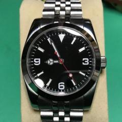
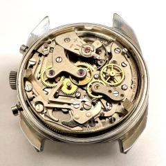
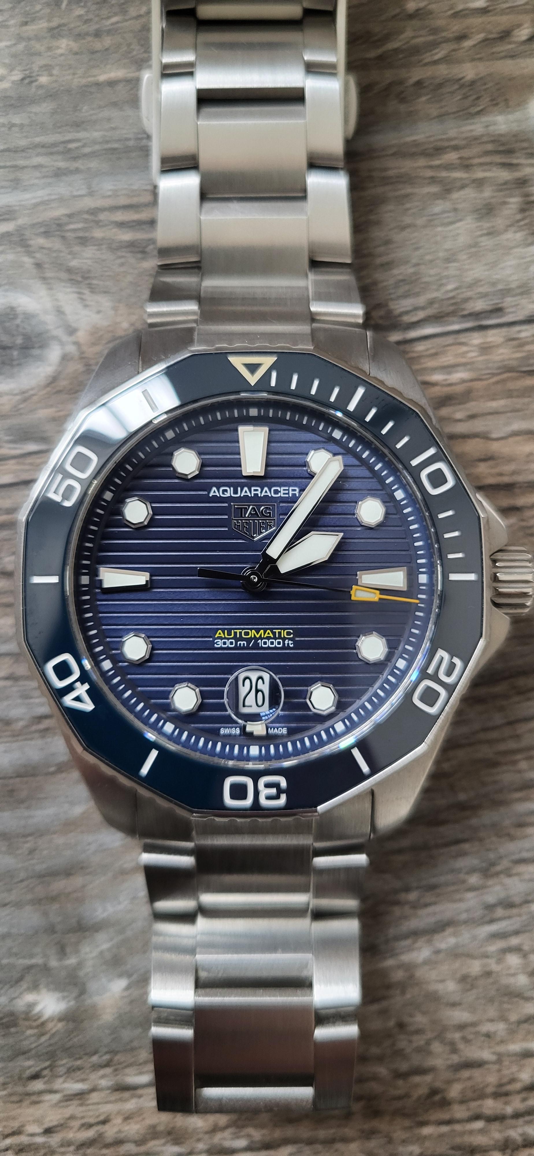
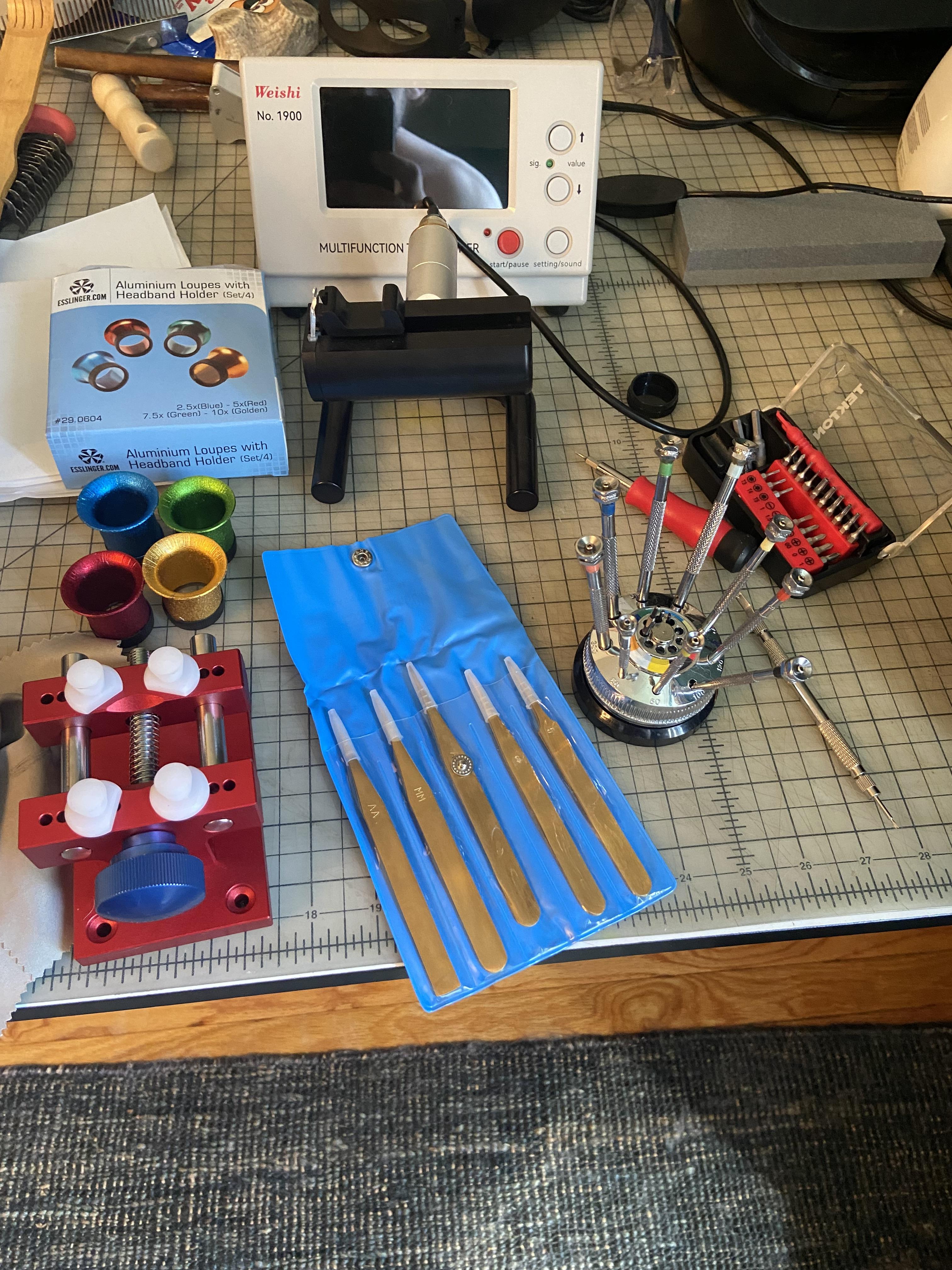
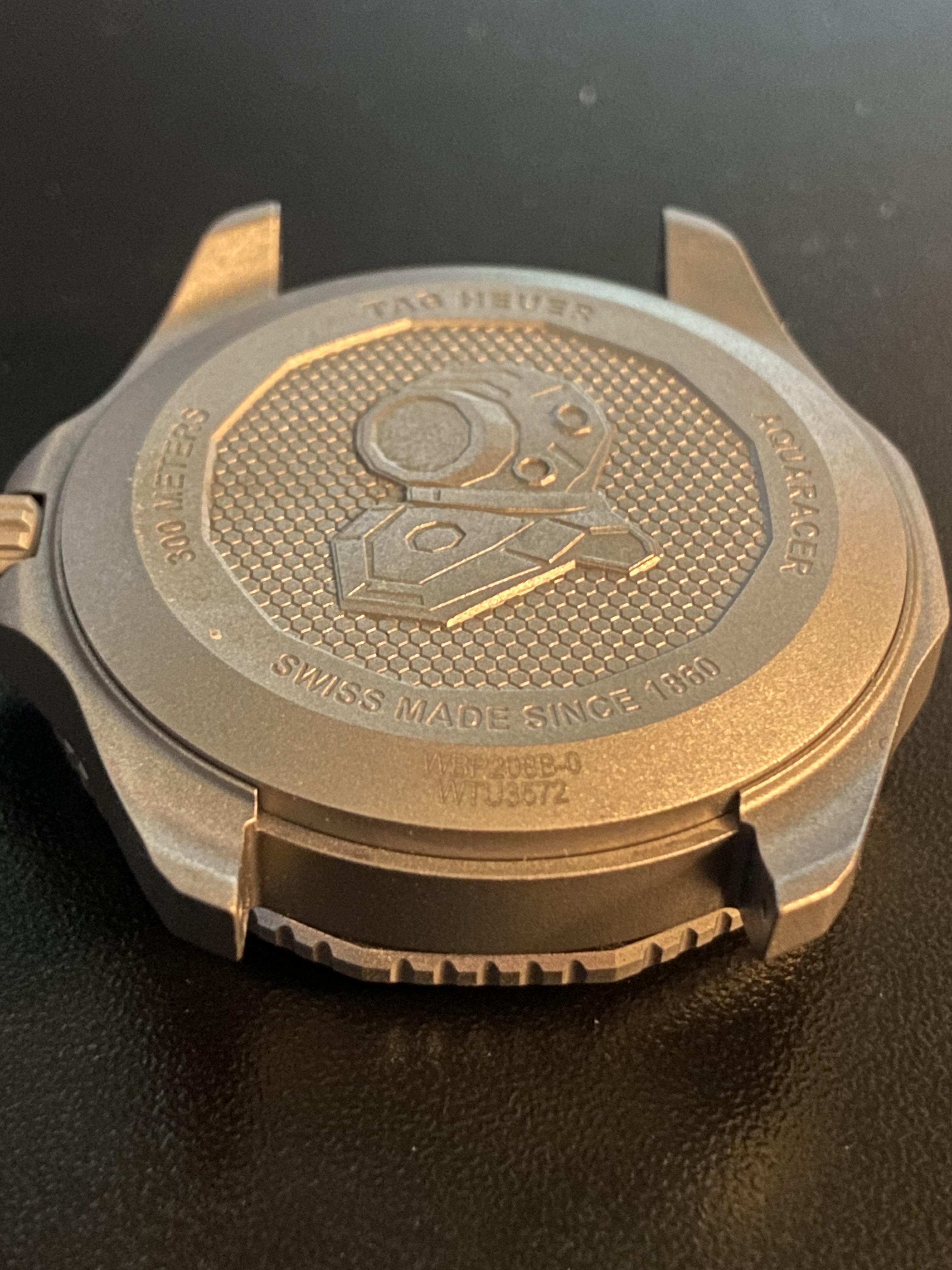
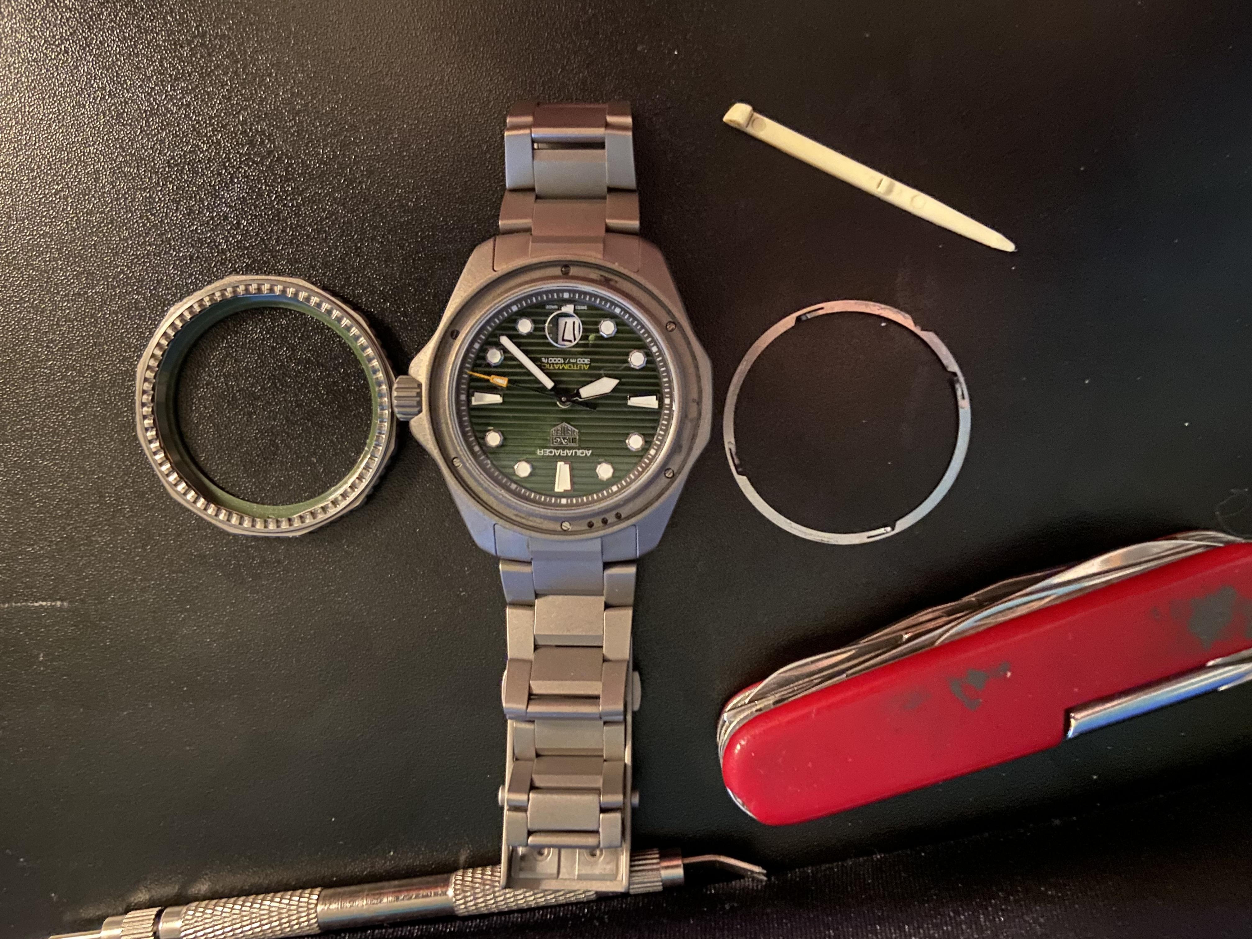
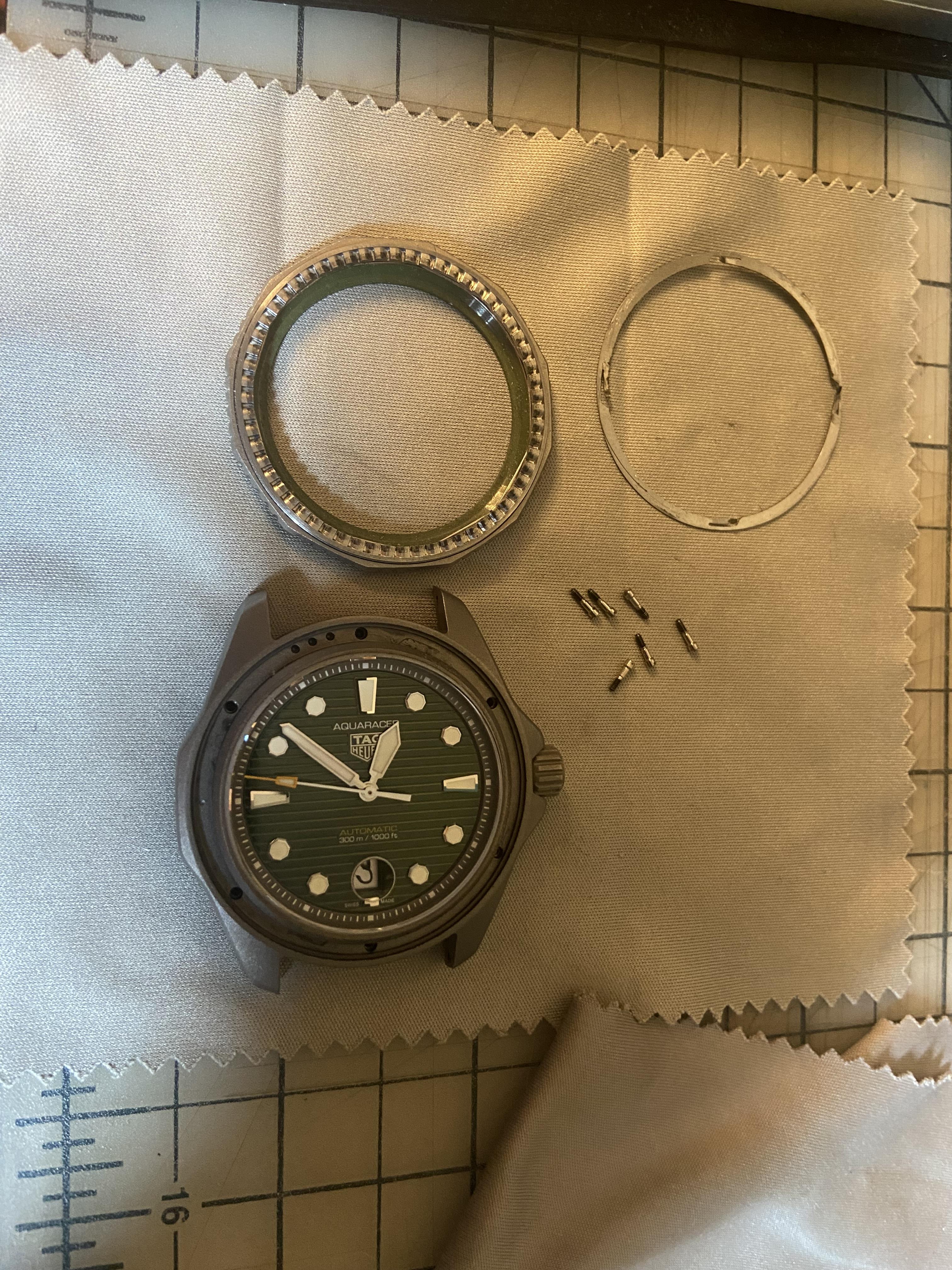
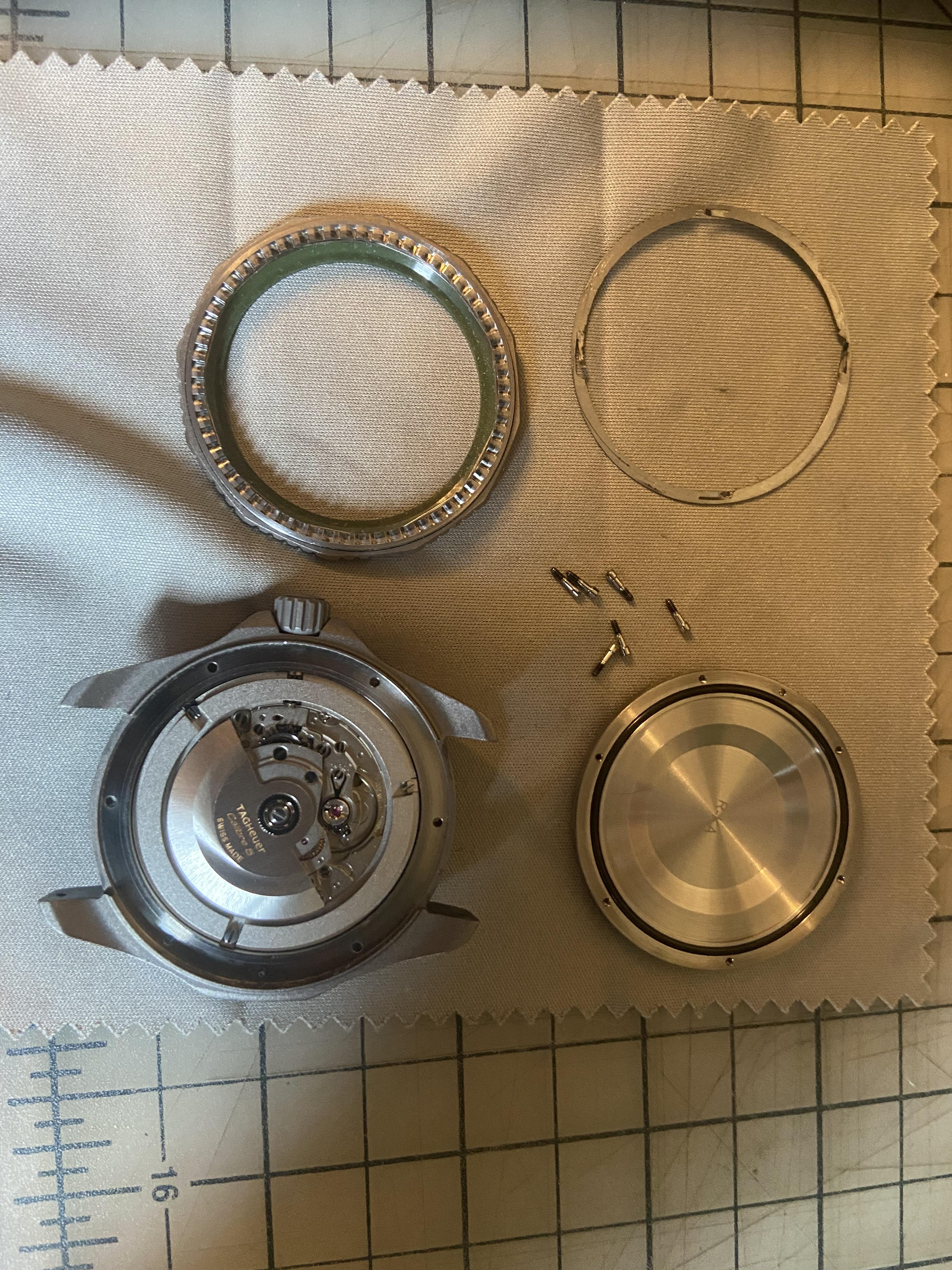
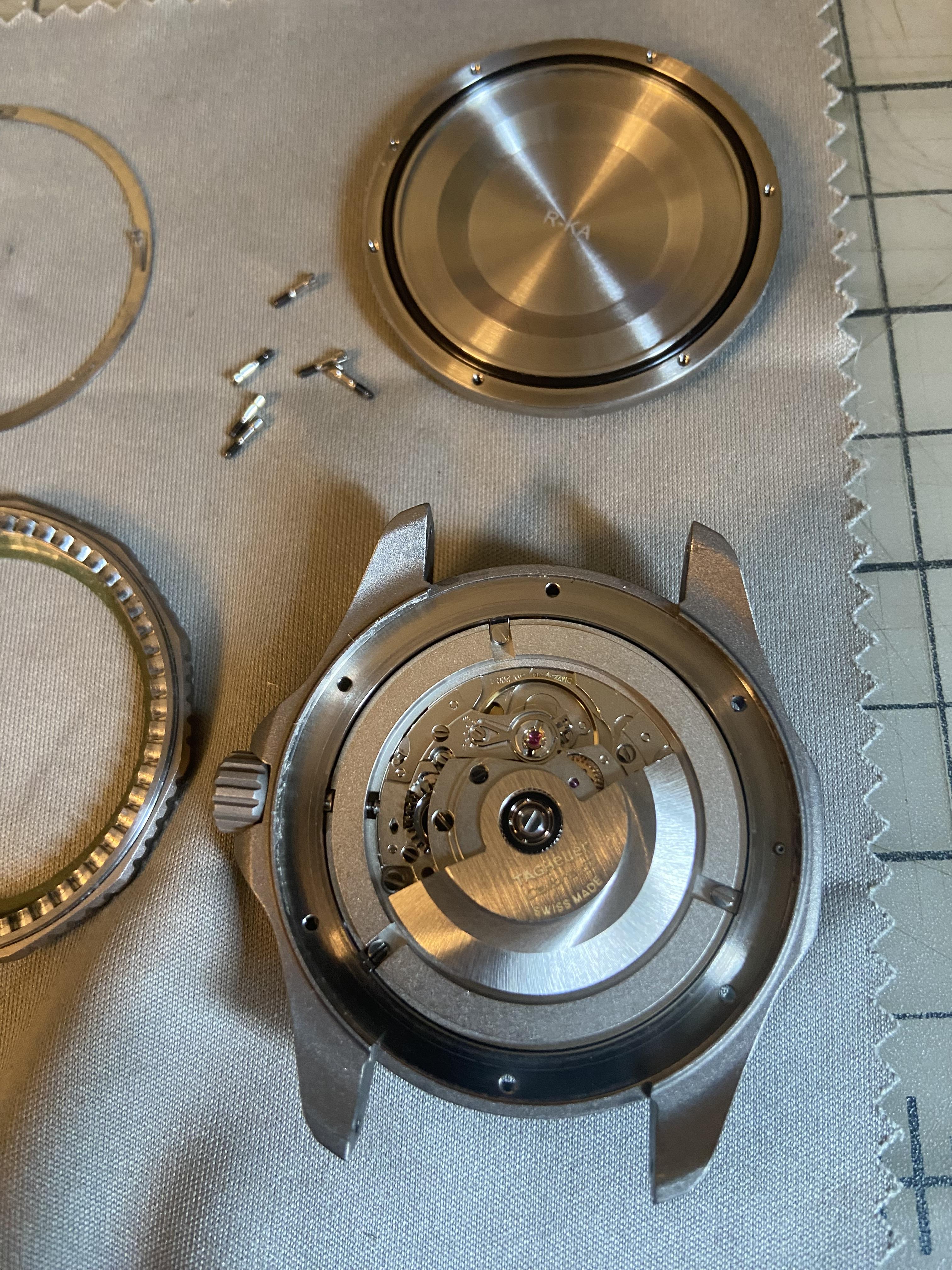
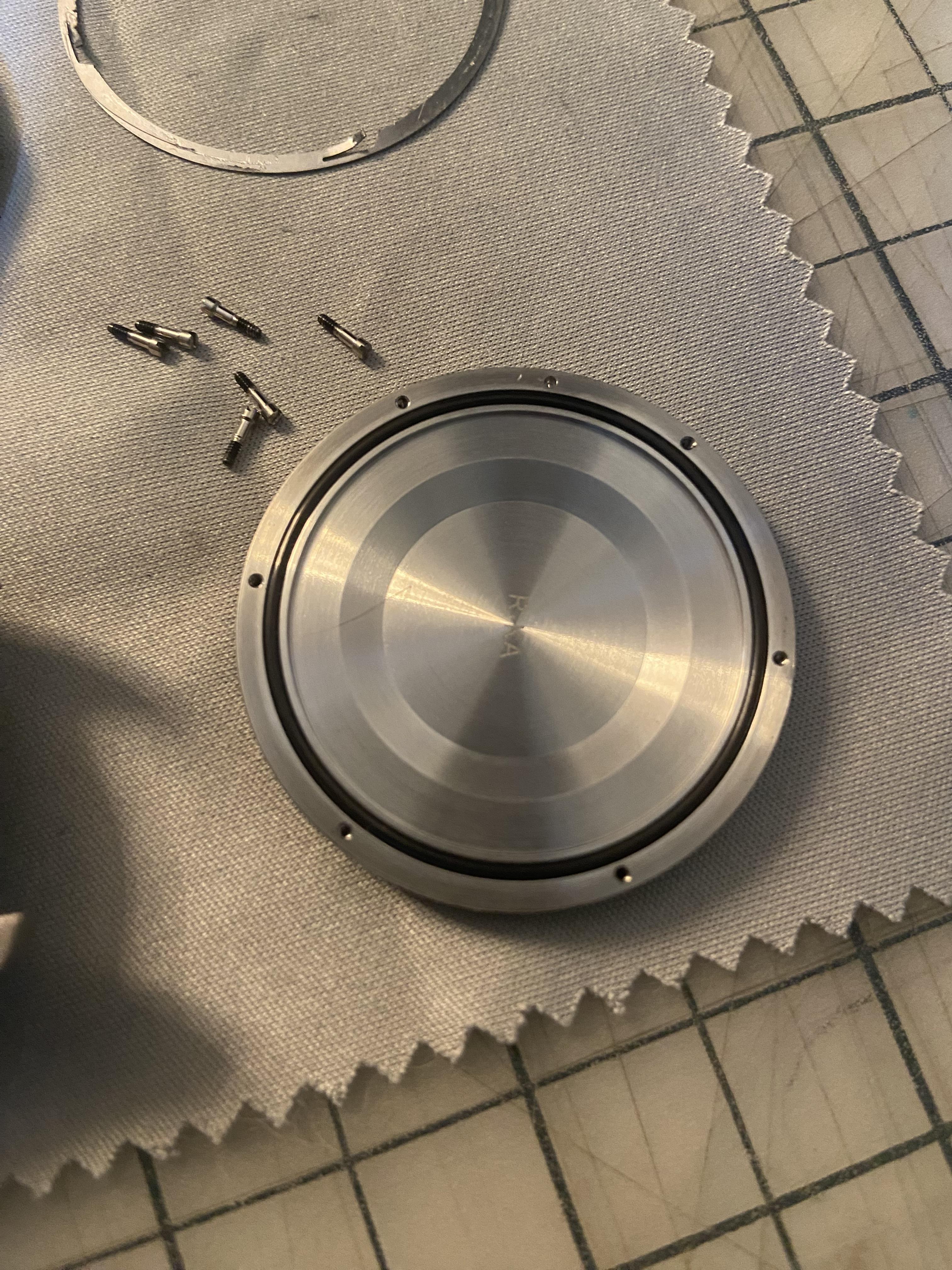
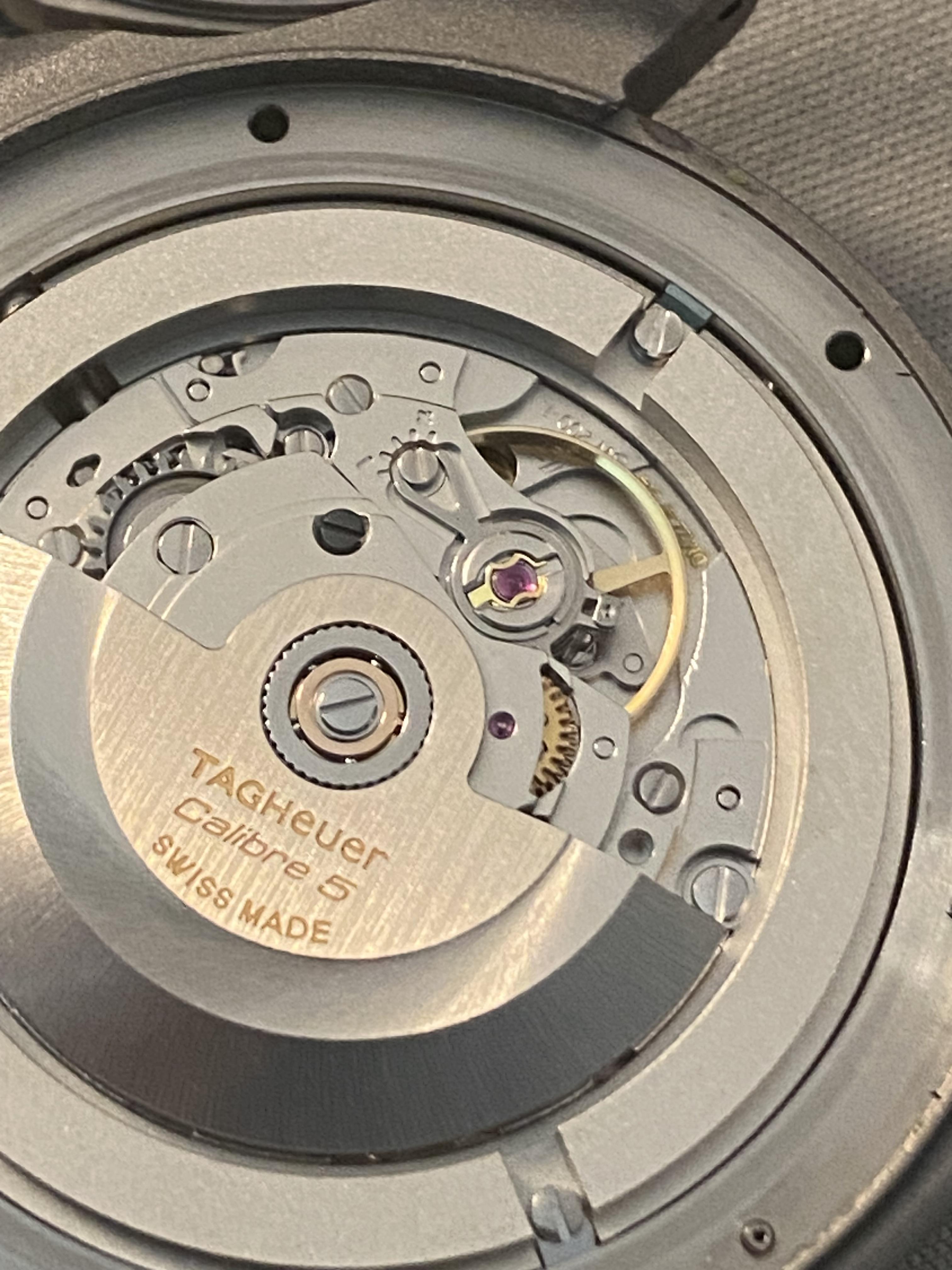
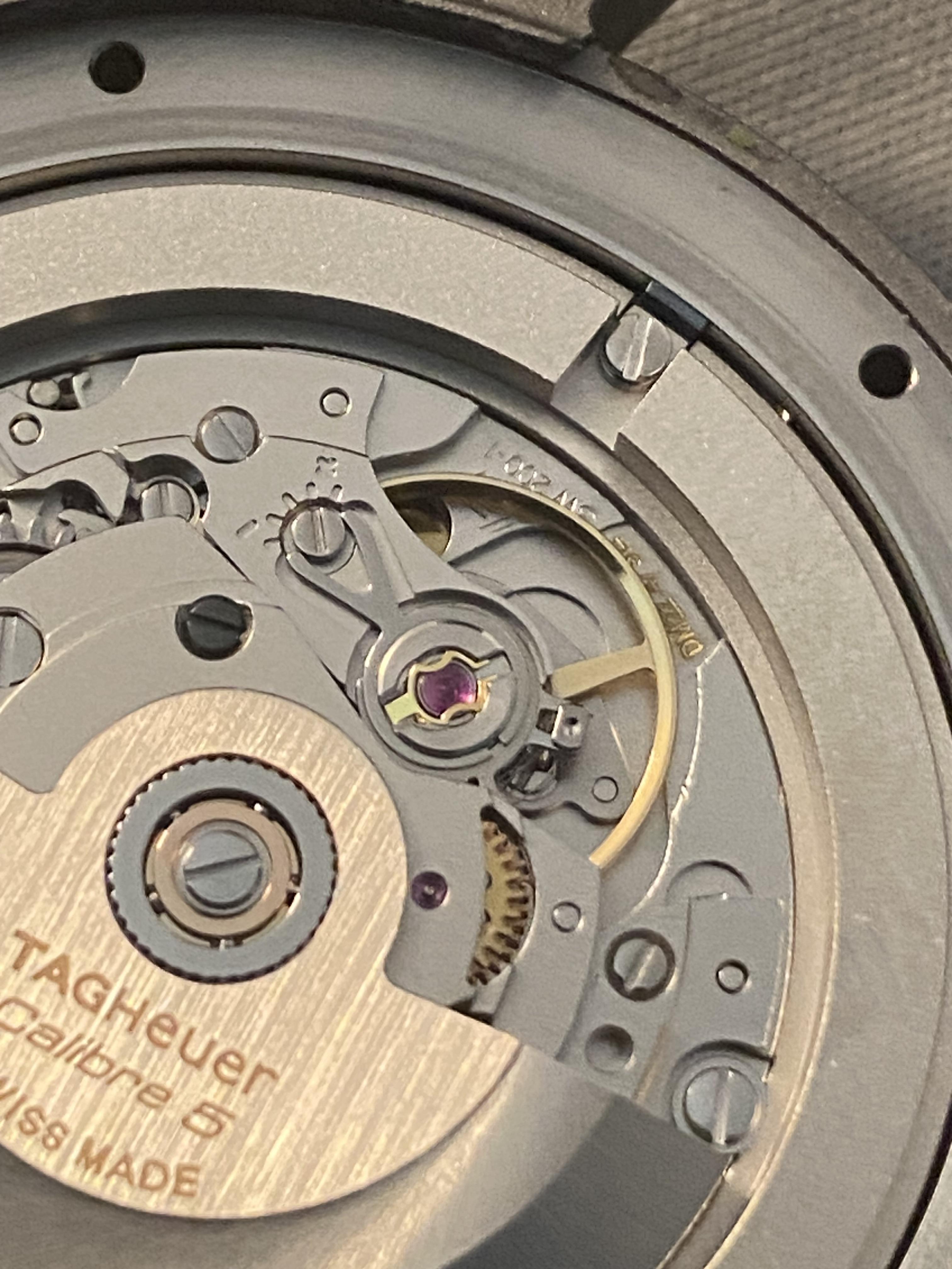
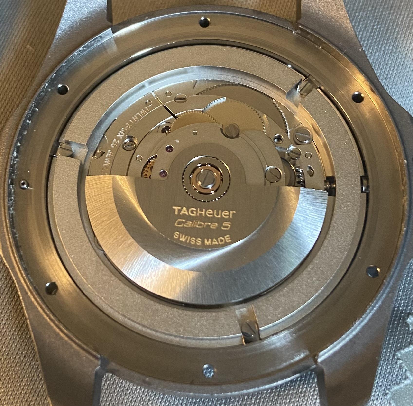
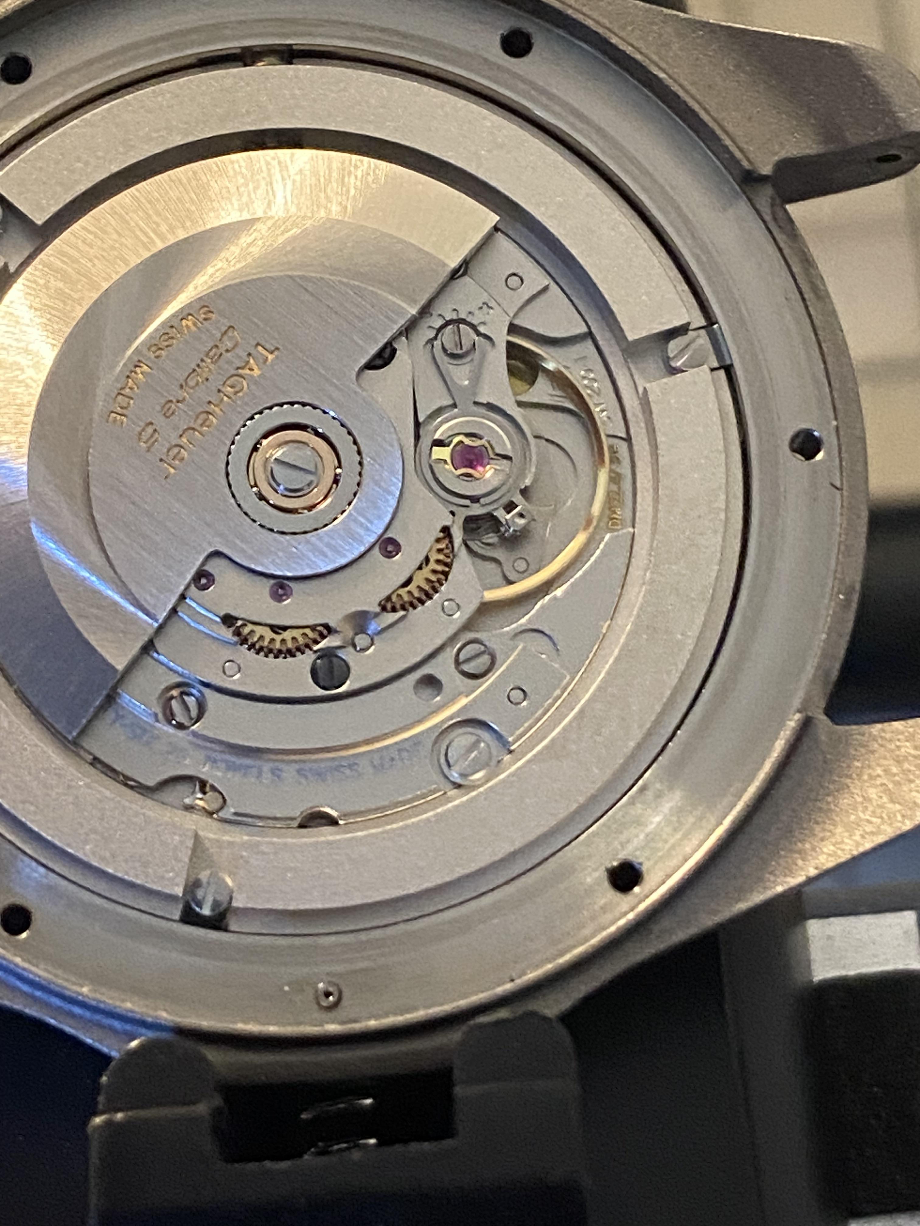
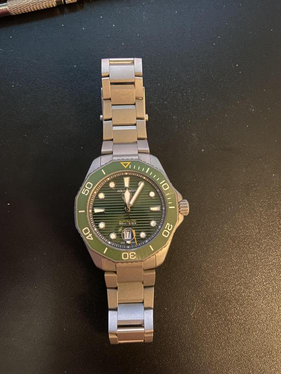
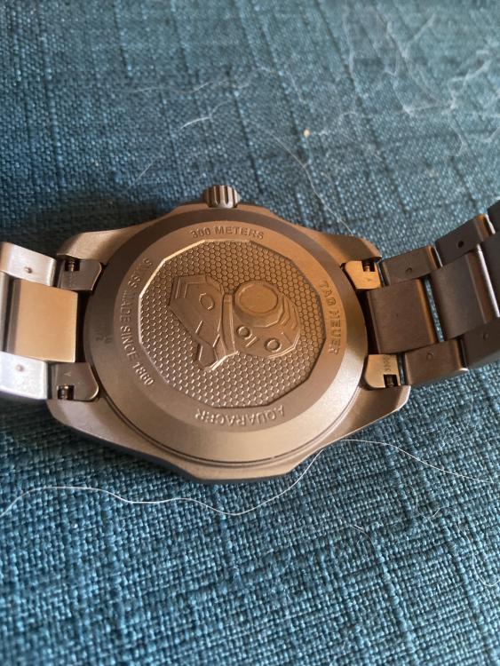
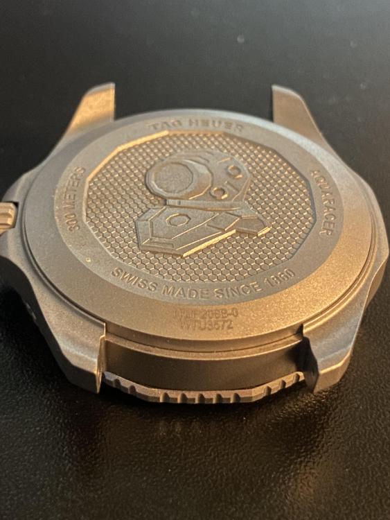
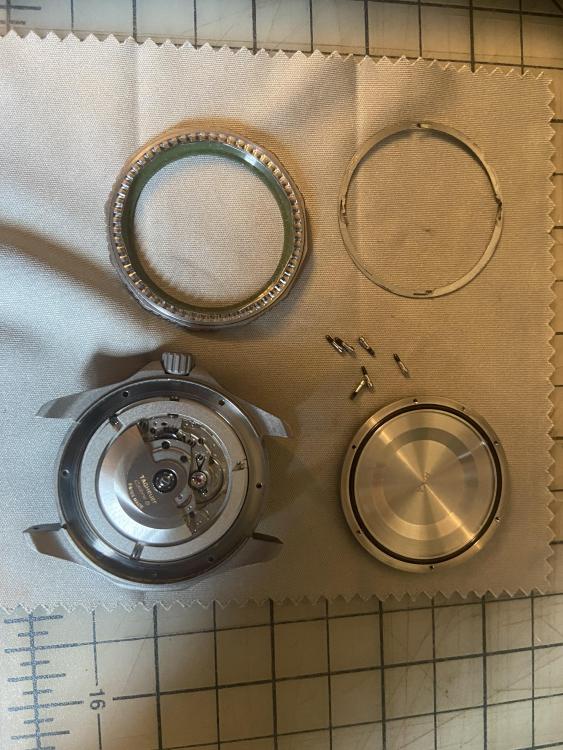
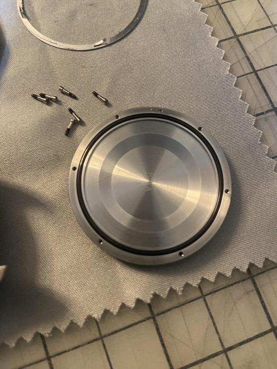
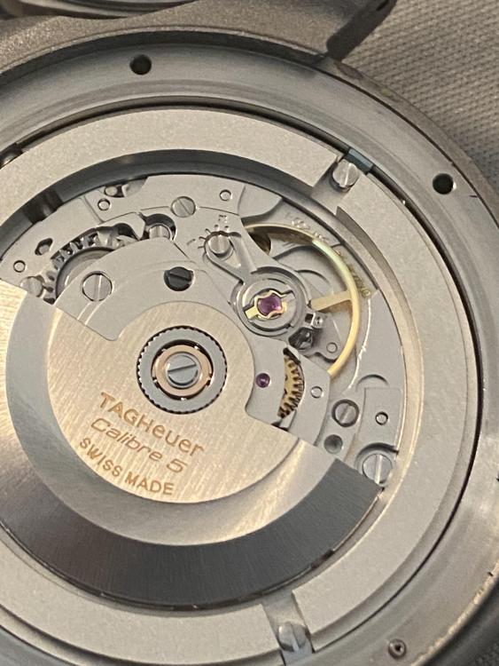
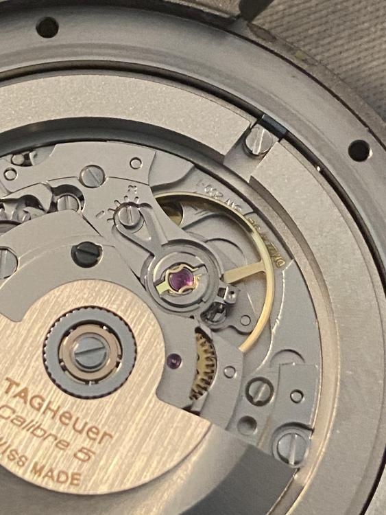
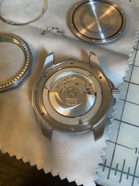
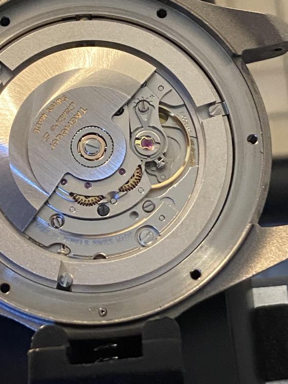
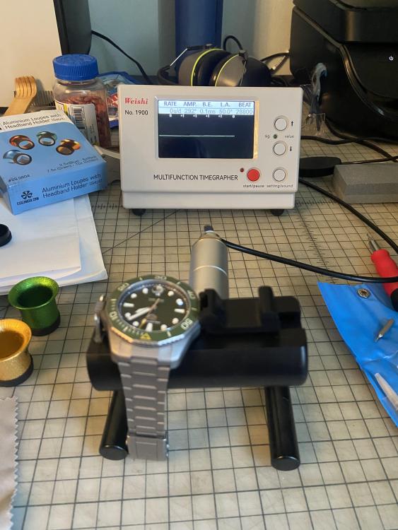
As I mentioned in some of my prior posts, I would probably work up the nerve to open the watch eventually. Well, this morning I woke up and decided to give it a go. In the intervening time, I bought a set of 10 watch screwdrivers, 5 brass pliers, a watch case vise/holder, and 4 loupes. They were all quite affordable around $10-20 for each set of tools. My wife had already bought me a time grapher some time ago, so I watched some YouTube videos on how to regulate an SW-200-1 and decided to try my luck opening the watch and turning the fine regulation screw a bit. The following posts will break down the steps of what I did. The image below shows the set of tools I used for the job. Here’s the watch in question. The images show the watch exterior front and back. The last one shows the dive bezel and the bezel spring removed, which reveals the six screws under the bezel holding the case back on. This is as far as I got during my last aborted attempt to open the watch. The next step was to remove the six screws under the dive bezel and spring that hold the case back on. At this point I thought I needed to unscrew the case back, so I put the watch in the vise and used the rubber ball method to try to unscrew the case back. I applied as much force as I could by hand, but it wouldn’t move the slightest bit. This left me quite confused, so I took the watch out of the vice and inspected it. As I was rotating the watch around and looking at it, the case back came loose and nearly fell off. Apparently those six screws are the only thing holding the case back on, so once they are removed, it comes off very easily. Then I inspected the movement. Tag Heuer calls this movement the Caliber 5 and gives very little information about it beyond that. However, through research on the internet, I surmised it was almost certainly a Sellita SW200-1. My suspicions were confirmed upon review of the movement. In the second picture below, you can see SW200-1 stamped into the baseplate near the top of the balance spring. In the third picture you can see the stamp saying 26 jewels. Another image zoomed in shows the 26 jewels a bit better At this point I wanted to regulate the watch. My previous post listed the performance in various positions. I’m reposting that information here for reference. regarding the daily rate, it is very consistently +10spd measured on my wrist. Every 24hours I wear it, it gains about 10 seconds, and it gains about 70 seconds in 7 days. So the +10spd is the average daily rate when I wear it 24hrs/day. on the time grapher the rates are all over the place. Amplitude is around 290-300 in all positions. On a full wind the rates are: Dial up it’s +10spd 3 down it’s +18spd 12 down it’s +5spd 6 down it’s +20spd dial down its +13spd 9 down it’s +4spd Those rate numbers correspond to the fine regulation screw being at the position shown above. This is how the watch was when I opened it. I spent about an hour tweaking the position of that screw back and forth while watching the rate change on the time grapher. My sense is that when wearing the watch it runs +10spd and that is the roughly the rate for the dial up position. That indicated to me that I should regulate the watch mainly focused on that single position as that seems to be the effective rate of the watch given my wearing habits. After several adjustments and trail and error while watching the rate on the time grapher I ended up in the position shown below. It seems odd to me that the fine screw was not centered for yhe watch coming out of the box from the factory. In the end I just moved the screw back to its centered position which brought the daily rate onI the dial up position to 0 and the crown down to +10. I was happy with the new rates, so I reassembled the watch and checked it on the time grapher. The image below shows the rate for dial up. I’m not sure how the time grapher rates will translate to real world performance so I’ll wear the watch for a few weeks and see how it does. In any case, I’m happy I didn’t break the movement or case during this adventure. I’ll report back on how it performs in a week or two when I have enough data to assess it. Thanks for everyone’s help and advice here. I don’t think I would’ve know how to proceed through this process carefully enough to avoid destroying the watch without your suggestions.


 1 point
 -
Yes- AS were particularly inclined to use left hand thead on both crown and ratchet wheel screws.1 point
-
If all you lost was the cap jewel and still have the chaton and hole jewel it's not the end of the world. A generic cap jewel with right diameter and thickness would work. Chances are you would find one that fits from assorted cap jewel sets if you don't already have scrap movements lying around that may have fitting cap jewels. You can start pulling your hair out if you lose the chaton/hole jewel though so definately be a lot more careful with those.1 point


.thumb.jpg.cb17a66989f1e796fd4217db2e9ca9df.jpg)