Leaderboard

.thumb.jpg.cb17a66989f1e796fd4217db2e9ca9df.jpg)


Popular Content
Showing content with the highest reputation on 02/03/25 in all areas
-
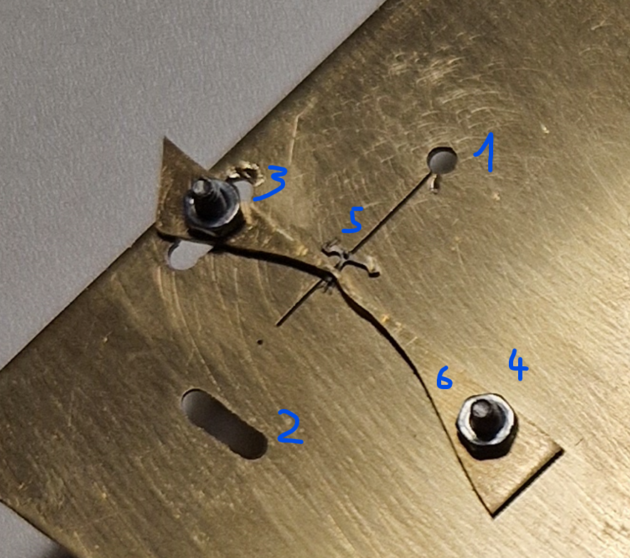
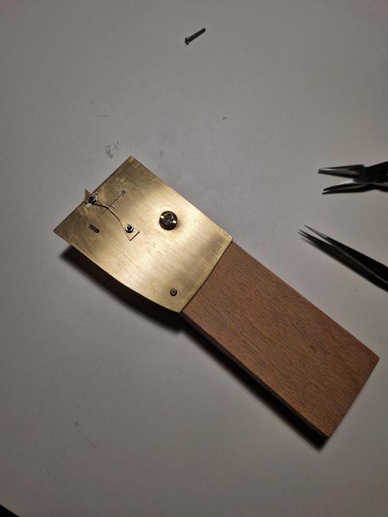
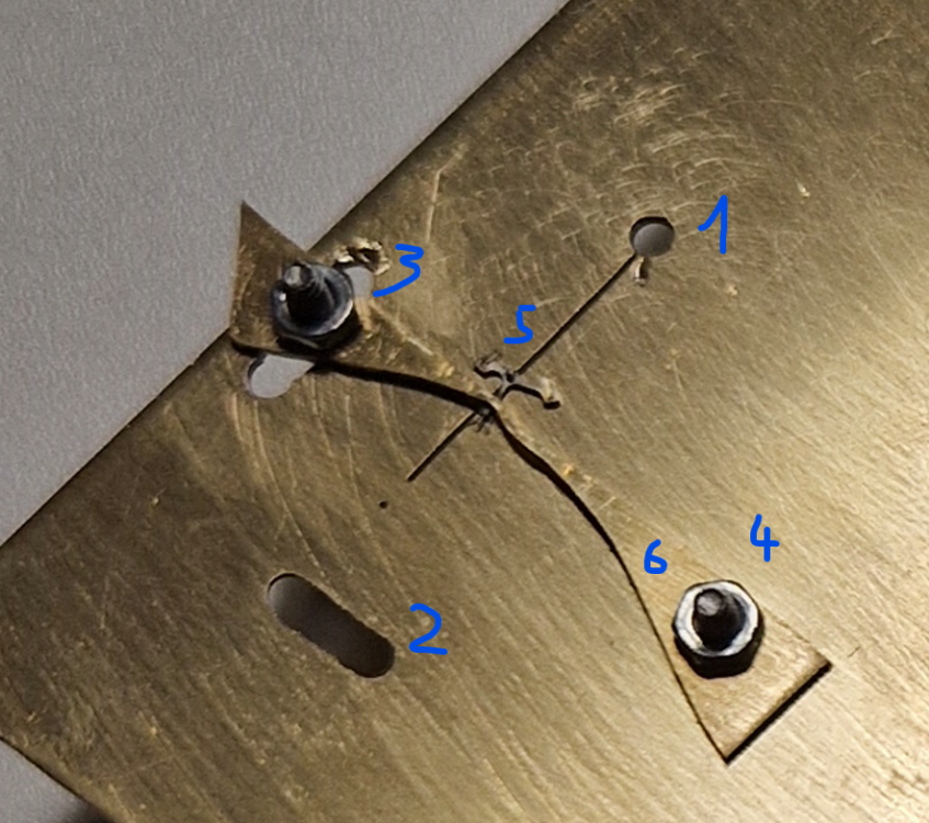
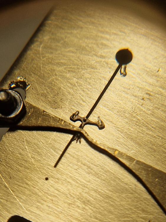
Hi all, so, for the fist time, I'm going to be repairing a pallet fork. Specifically, repositioning a pallet stone that has come off and then applying new shellac. In order to do so comfortably, I created this tool. I tested it once with a spare fork and it seems to be useful. Ingredients: - 1mm thick brass sheet: https://www.cousinsuk.com/product/sheet-brass?code=B55335 - a cheap saw : https://www.cousinsuk.com/product/saw-frames-fixed?code=P33903 - ..and blades: https://www.cousinsuk.com/product/value-premium-saw-blade-set - a cheap set of M2 screws and nuts like this: https://www.amazon.co.uk/Screws-230pcs-Stainless-Assortment-Storage/dp/B08T8BB1YN - a spare chunk of 2cm thick, heavy multi-layer wood panel - non-watchmaking electric drill with a 2mm drill bit Building steps: I don't have many tools, so I free-hand cut a piece of the brass sheet, approx 8x5cm. I then drilled a few holes in it. - No 1: a 2mm hole to then cut a slit (No 5) with the saw to fit the pivots of pallet forks. After taking the below picture, I used thin strips of sanding paper to taper the slit (to accommodate different sizes of pivots). - No 2 and 3: I drilled this hole and again used the saw to create a 2mm wide slot. - No 4 is also a 2mm hole. - now I sew out a piece No 6. Let's call it "holding bar". Wide enough at the ends to accommodate 2mm screw holes and tapered in the middle to accommodate different sizes of pallet fork levers. - I loosely attach piece No6 with 2mm screws and nuts. - two additional holes though brass and a hand-cut piece of 20x5cm wood. Then fix the brass to the wood. The brass place over-hangs the wood so that screw holes 1-4 are still free from below. - the heavy and large piece of wood creates a solid and flat base that keeps the brass sheet nice and stable when working on the fork. Of course, it's not too heavy to be picked up and held over a sprit lamp. Operation: - loosen the screws No 3 and 4 and lift the "holding bar" (no 6). [For additional positions, one can also use the holes No 1 and 2 (in case you were already wondering...)] - insert the pallet fork pivot in an appropriately sized section of the tapered slot. - position the holding bar (carefully!) over the lever section of the fork. The slot No3 allows different positions. The "holding bar can also be turned around/upside down for more flexibility. - Carefully secure the screws to hold the "holding bar", keeping a close eye on the fork and pivots. -> now the fork is secured and ready to be worked on. Advantage of the slit and the fork position as below: this allows to separate entry and exit stones for separate cleaning and heating. By the way, I tested using a soldering iron (15 bucks on Amazon) to heat only specific areas of the brass plate or fork. Played around with shellac for the first time. I found it very useful! E.g. if I set the iron to 400 C°, I would just slowly come near the fork (like 1-2mm distance) and the shellac would gently melt. Alternatively, setting to 180°C (minimum on that soldering iron), I could just touch the pallet for slots from the outside (not touching the shellac) and that would also slowly melt the shellac. I found that this gave me a lot of control. I wonder what you think of my tool
 7 points
 -
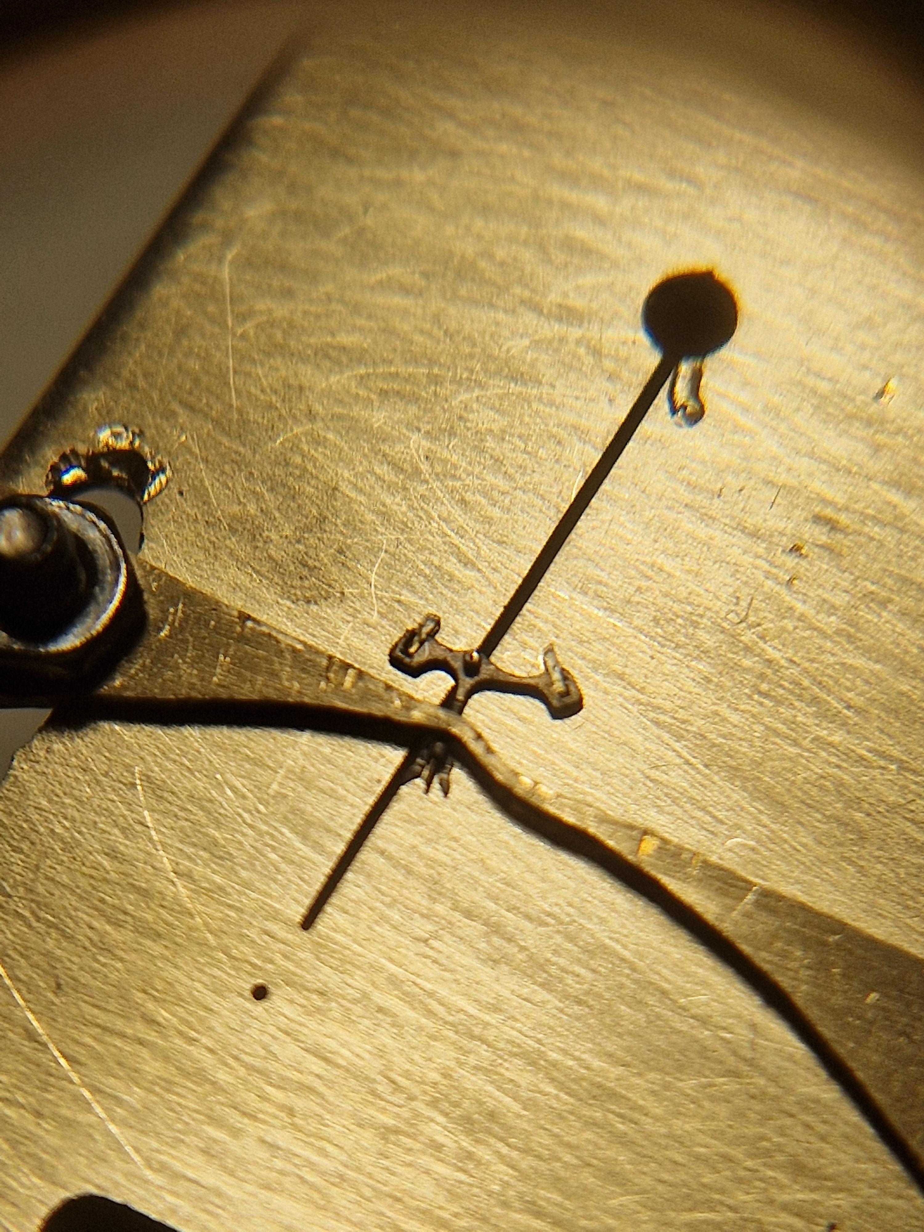
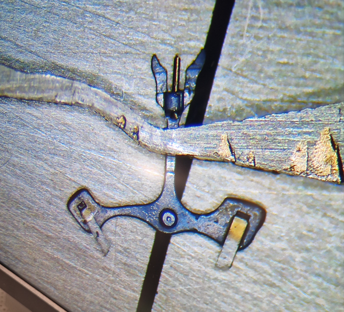
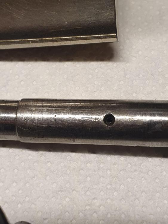
This could be cracks in the shellac only. It is not clear from the picture. If so, heating will make it melt and the cracks to disappear. If after all the stone is broken, then if the shellac holds it tight, still can work fine for many years6 points
-
I remember the speaking clock. You dialed 1234 points
-
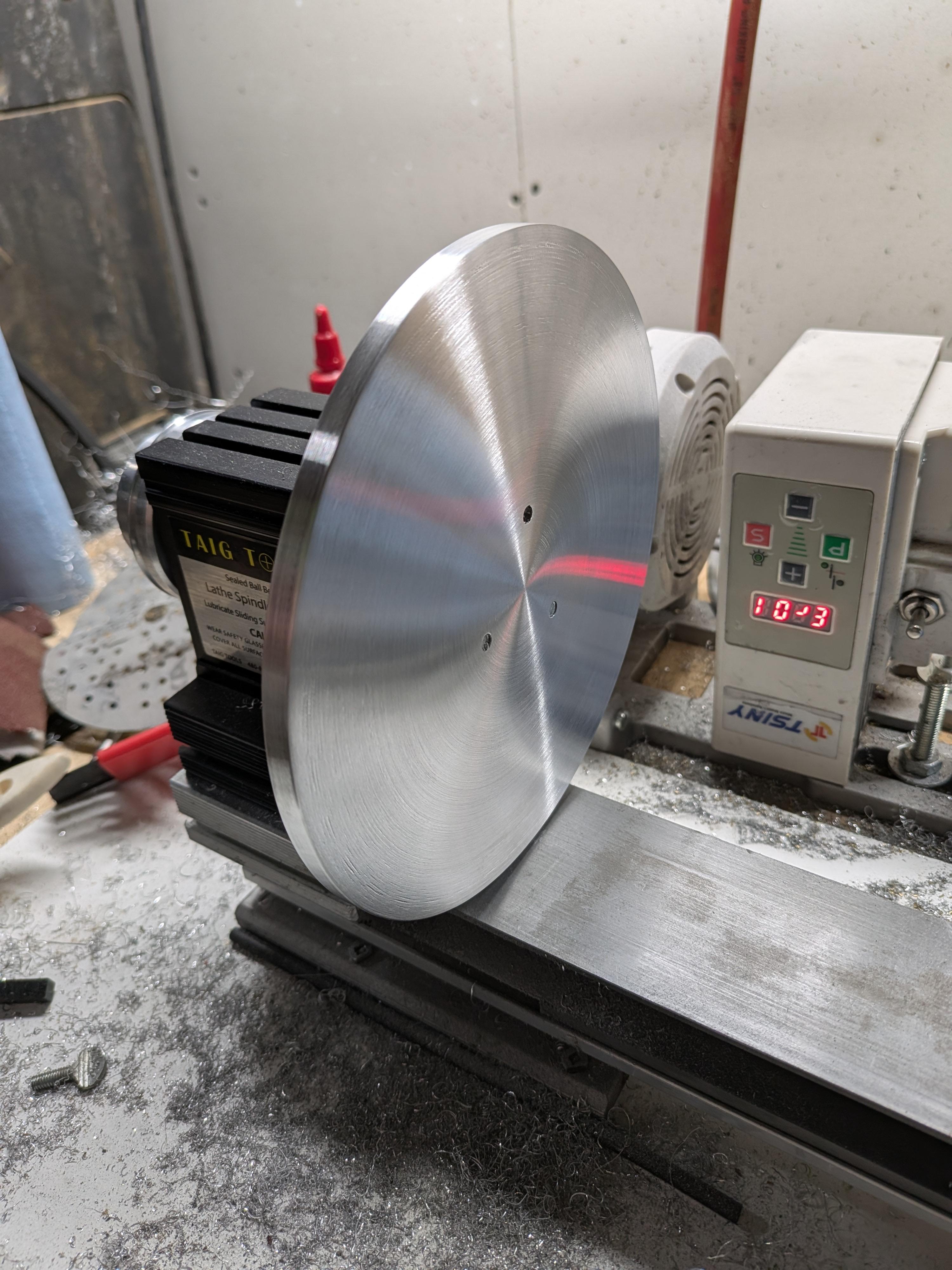
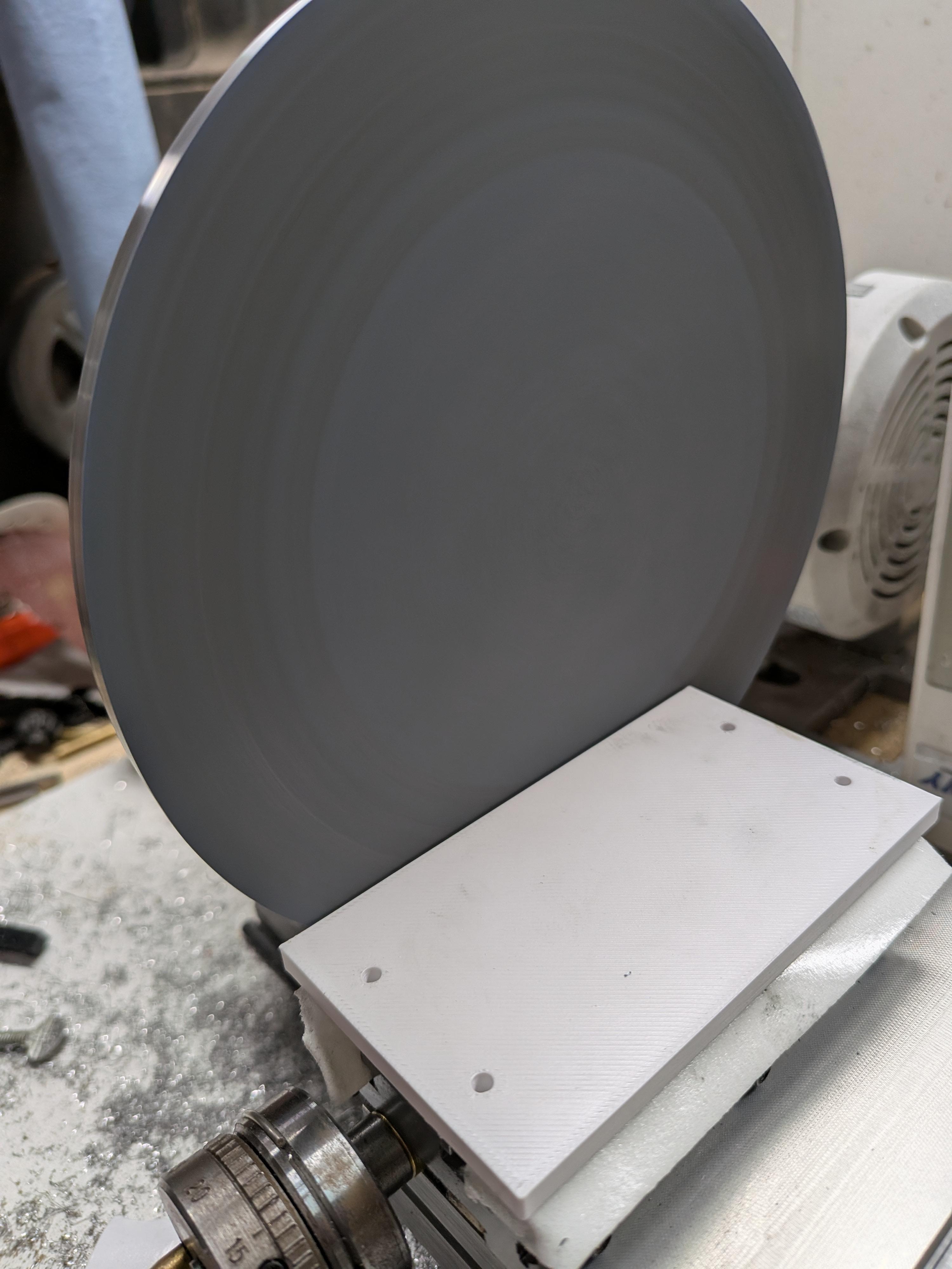
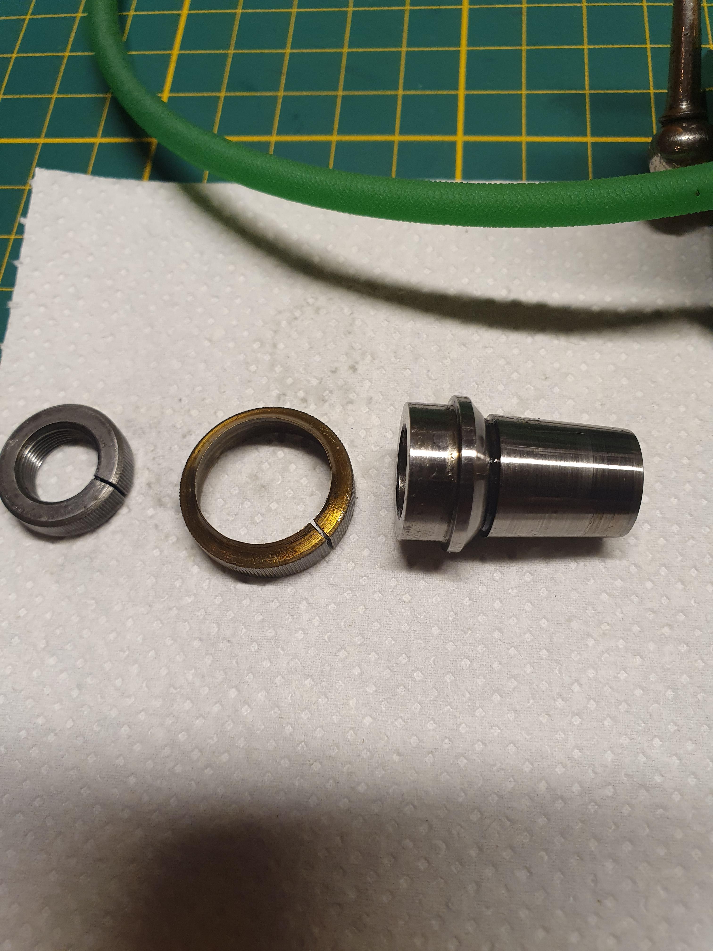
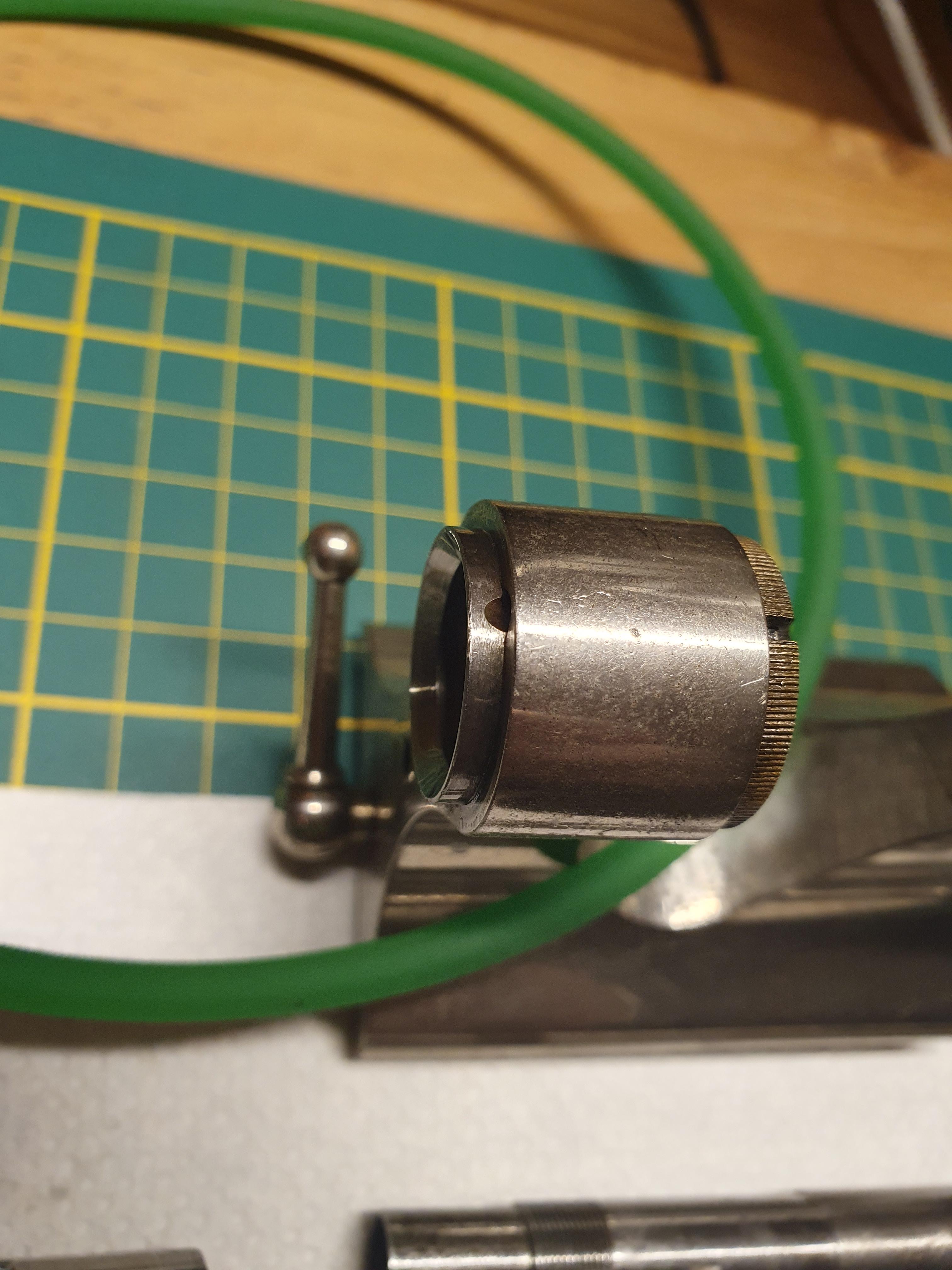
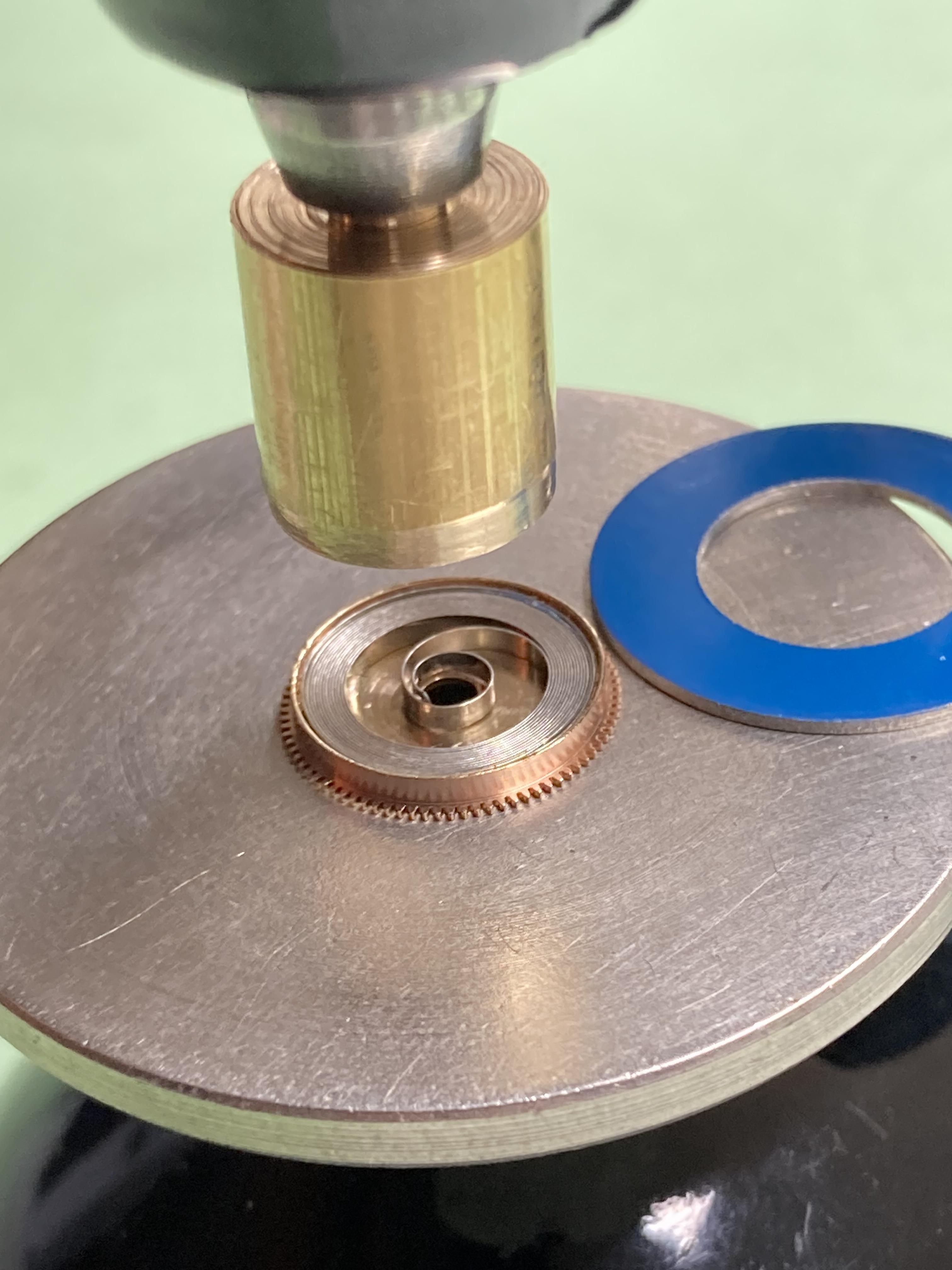
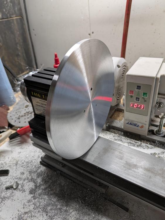
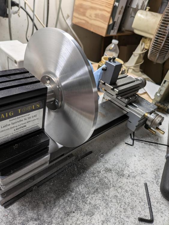
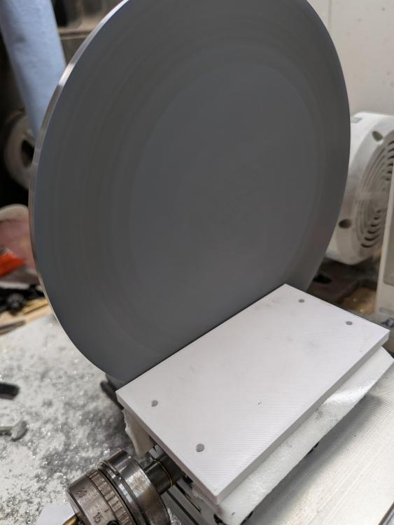
Hello all. As stated in other topics, I'm working on a lapping table setup, as I do a fair amount of restorations, and things are needing to get more precise. With my recent addition of an impulse micro welder, lapping is necessary. To start off, I have a few lathes, and the one I'll be using is my Taig Micro Lathe. I purchased it unassembled, as I wanted to modify it readily. I use a sewing machine motor to drive it, and it has a lot of adjustment on speed. In order to do this, you need this tailstock riser to use on the headstock, and this spindle mount to attach your Lapping Plate to. I ordered some 6 inch aluminum disks that are 1/4 in thick. After finding the center, I placed the spindle mount on the center, then drilled and tapped the holes. Then I used a vertical belt sander to reduce the OD of the disc enough to mount the piece on the lathe so it spins freely. Then I faced the part as best as I could(cross slide only has so much travel) and finished it off with 240 grit sandpaper. I attached some 2k grit sandpaper for now, but will be replacing it with lapping film. As for the table, I'm 90% done with the build, and should have it done this week. I'll add that to my post. The white plate below is just the base and is not centered on the headstock axis. The lapping vise as seen in some European restoration videos is extremely expensive. I have designed and made a fixed polishing device, similar to the one by horotec. I have designed and am prototyping a 2 axis vise for rotational bevels. My last design is going to be the 3 axis vise, but I'll get to that one later. Attached are some photos of the lapping plate for the lathe.
 3 points
 -
Bit strange that he called it a special key....the T315 lifting tool. I feel some fibbing going on there as it was just a regular claw tool inc. the spacing plate, he even attached a sticker to the claw tool that said key T315 very wierd. I have the T315 and it looks nothing like a claw lift ???. The seller assured him it was the key 315T do you have something in your eye Paul ?3 points
-
In the early days we used to check the time on our watches against public clocks to see if they were accurate. Nowadays it's the other way round.3 points
-
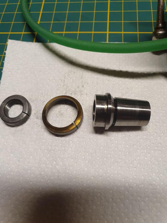
Yes, the rear bearing in the headstock should not move. And the oil covers should friction onto the bearings pressed into the headstock, and not move with the spindle either. They are usually split, but it could be you some that are just a friction fit- but, they shouldn't contact the spindle. As you can see in Caseback's photos, the spindle has a divot for the pulley screw; so no tapping out the spindle if that screw is in place. You could try an extractor for broken screws, it will hopefully grab on the (now smooth) hex opening. The rear spindle bearing is usually a light press fit on the spindle and is keyed. You will almost always need to knock the spindle out with a brass drift- just be careful not to damage the key, which is usually integral with the bearing. Also be careful to line the key up with the keyway when reassembling. The loose rear headstock bearing needs to be addressed. Once it's all apart and clean get it in place and tap it home with a soft faced hammer, if it seems secure it should be alright, but in the event it still wants to move, you can use a little bit of Loctite sleeve retainer like 638 to hold it. Just the smallest amount evenly distributed, a band maybe 2-3mm wide. If there's too much it will almost certainly not fit all the way in the opening correctly.3 points
-
I always replace them.3 points
-
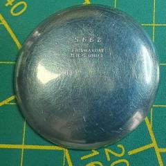
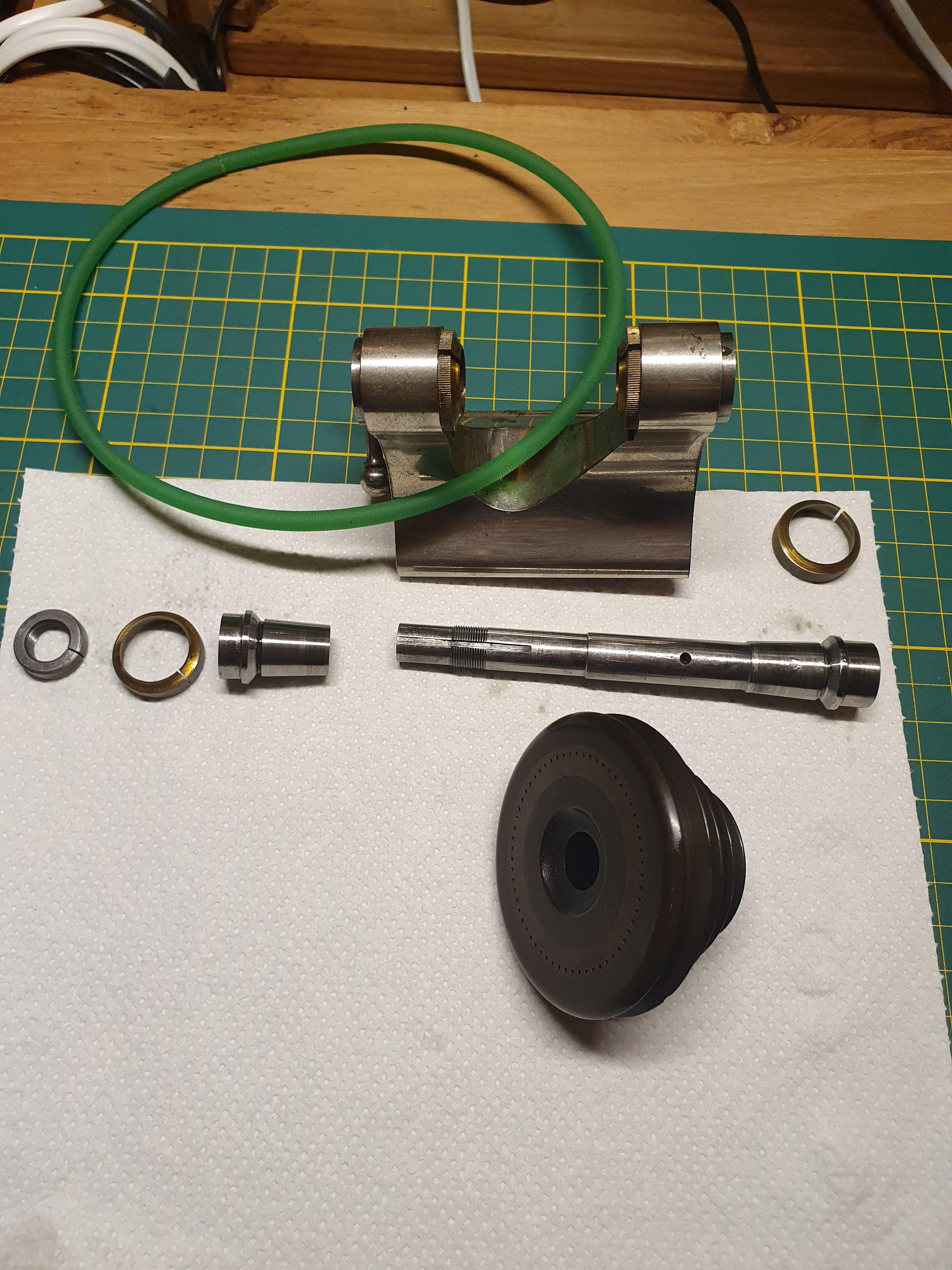
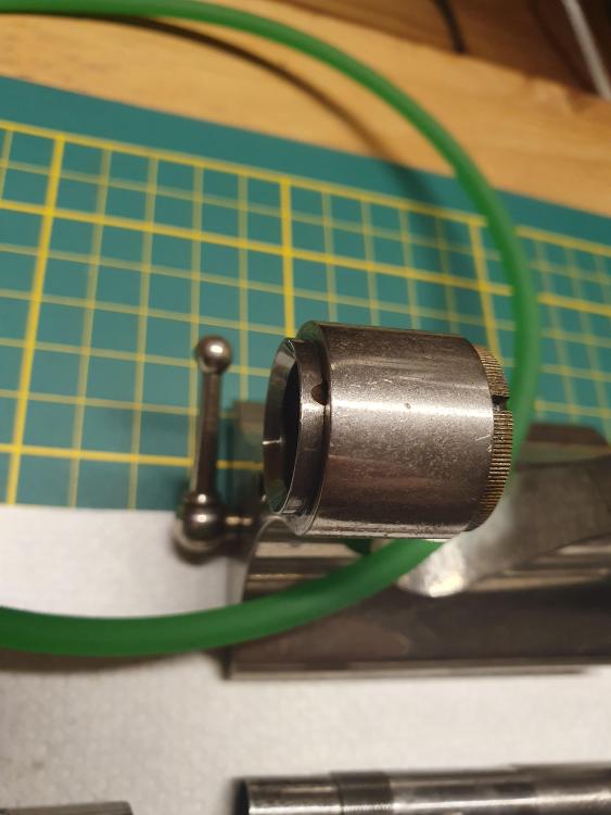
The headstock of my Wolf Jahn WW lathe looks very simular. Maybe @nickelsilver knows if it actually is.Here you see it it diasassembled: It has a recess in the spindle for the grub screw, and if your pulley only has the one screw it is very likely your's will be the same. If it was friction fit I would expect 2 or 3 screws. Tapping is not advisable. It is possibly/probably what caused the crack in the pulley. Edit: looking at your first photo: are you sure you're looking at a grub screw or are you seeing the recess in the spindle and is the pulley glued on?? If there is a grub screw: You could try to superglue something in the grub screw as a first try, but I don't expect that will work if the screw itself is stuck/glued. 2nd option: get a LH thread screw slightly bigger then the hole I see in the grub screw and try screwing that in. If it "bites" you can pull/turn the grubscrew out. Third option: drilling and tapping in LH treads (also tricky but might just work). Fourth: carefully drilling it out. After removal drill and tap a new hole. The oil hole on the back should be stationary. This is alarming.. If the construction of yours is indeed simular to mine (which I think it does), that part is the "outside cone" of the rear bearing and it should not rotate. A rotating oil hole would also be lubricating the area around the lathe including you: not a very sensible construction.

 3 points
 -
Place it on a fire brick and heat it with a blow torch till cherry red, then quench it in cold oil. It will be fully hardened and brittle at this point. (Assuming that the steel is hardenable.) Polish it back to steel color then heat it again till straw color and quench it.3 points
-
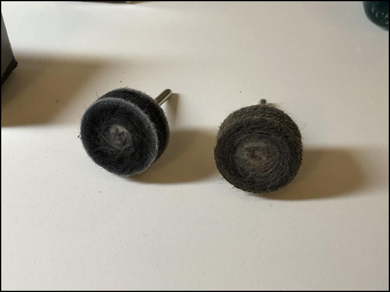
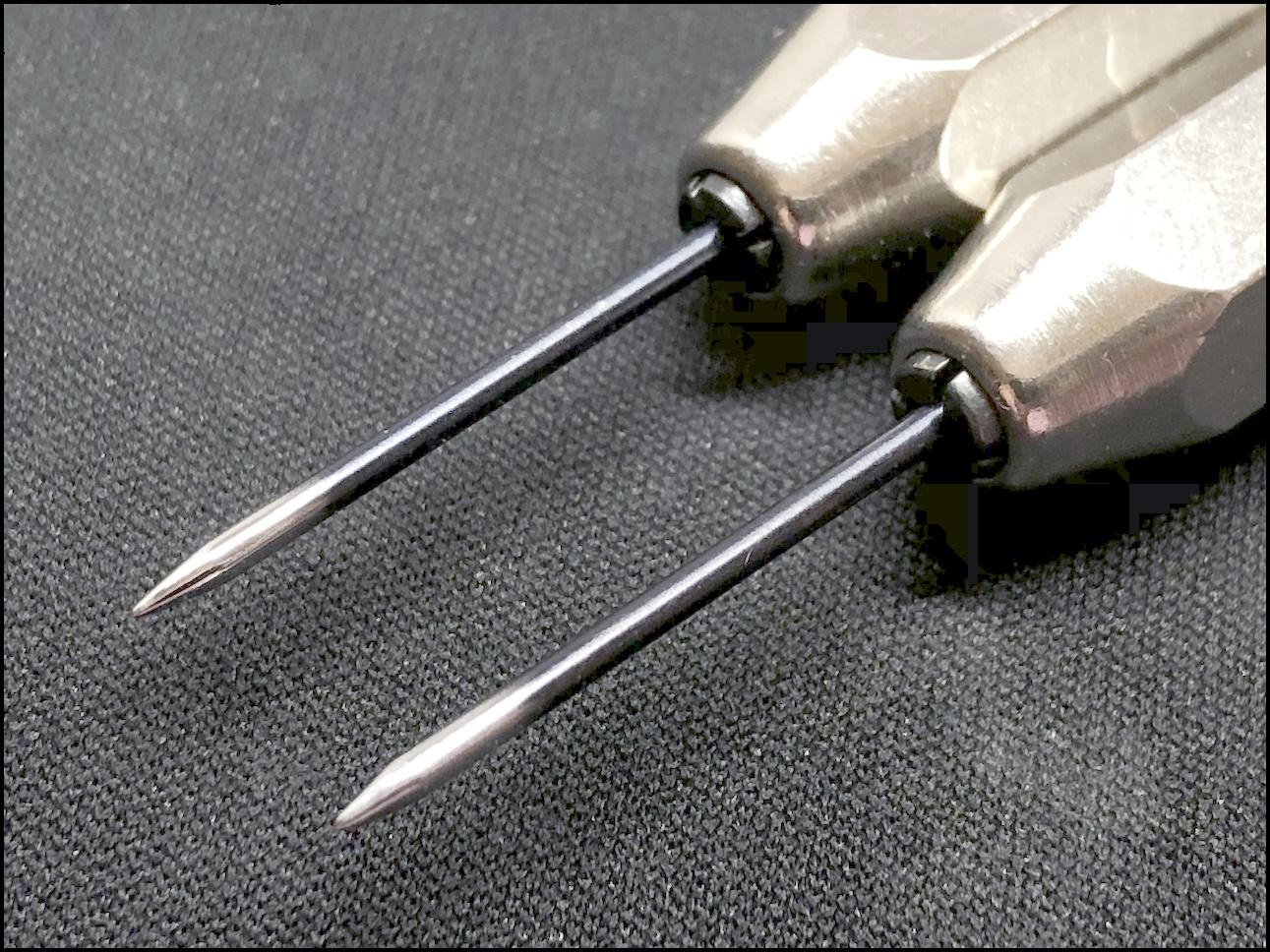
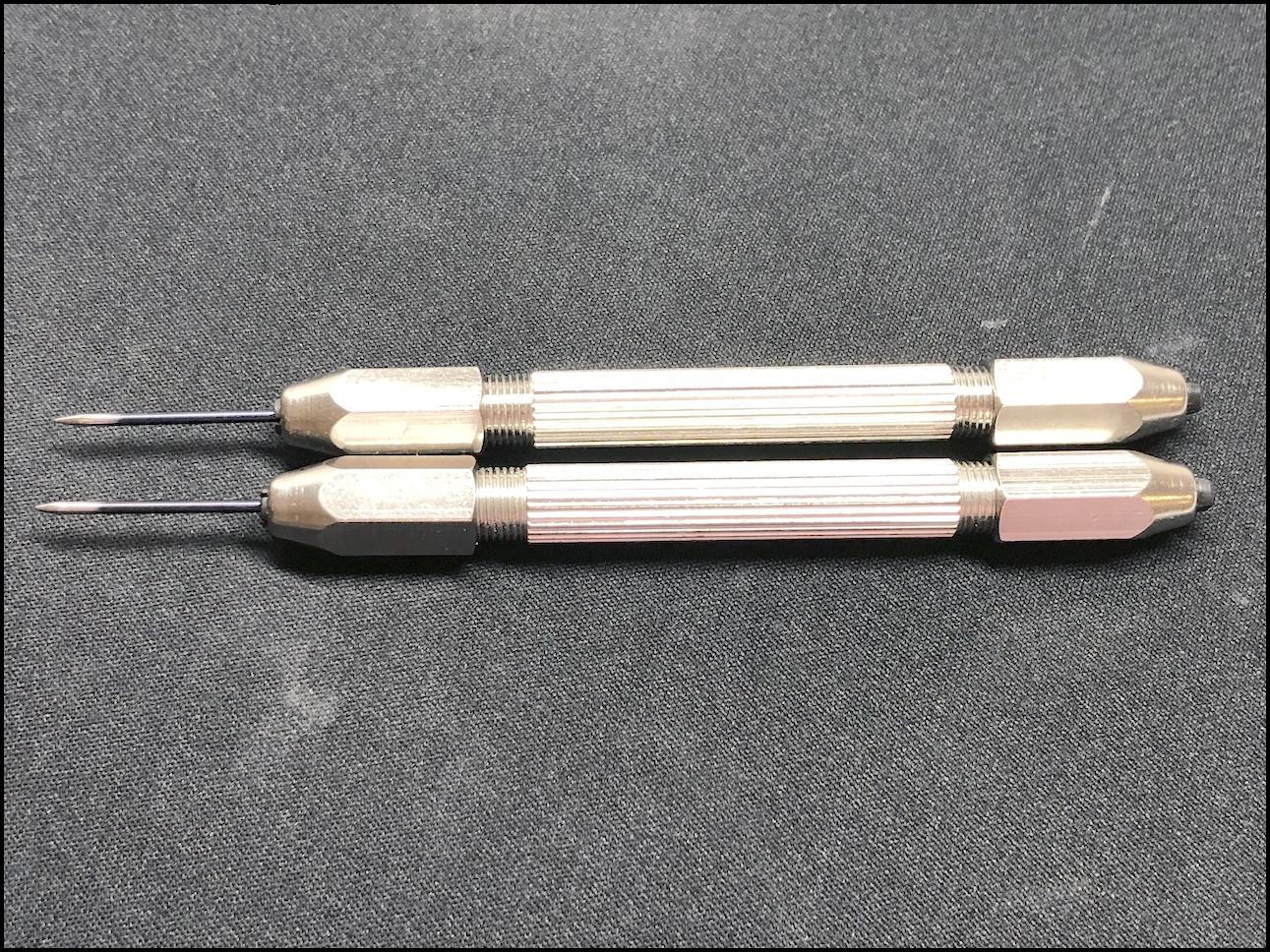
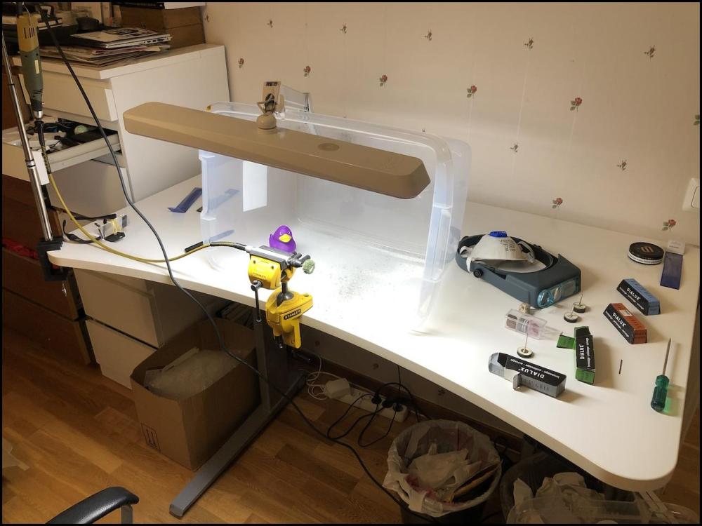
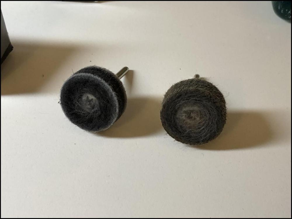
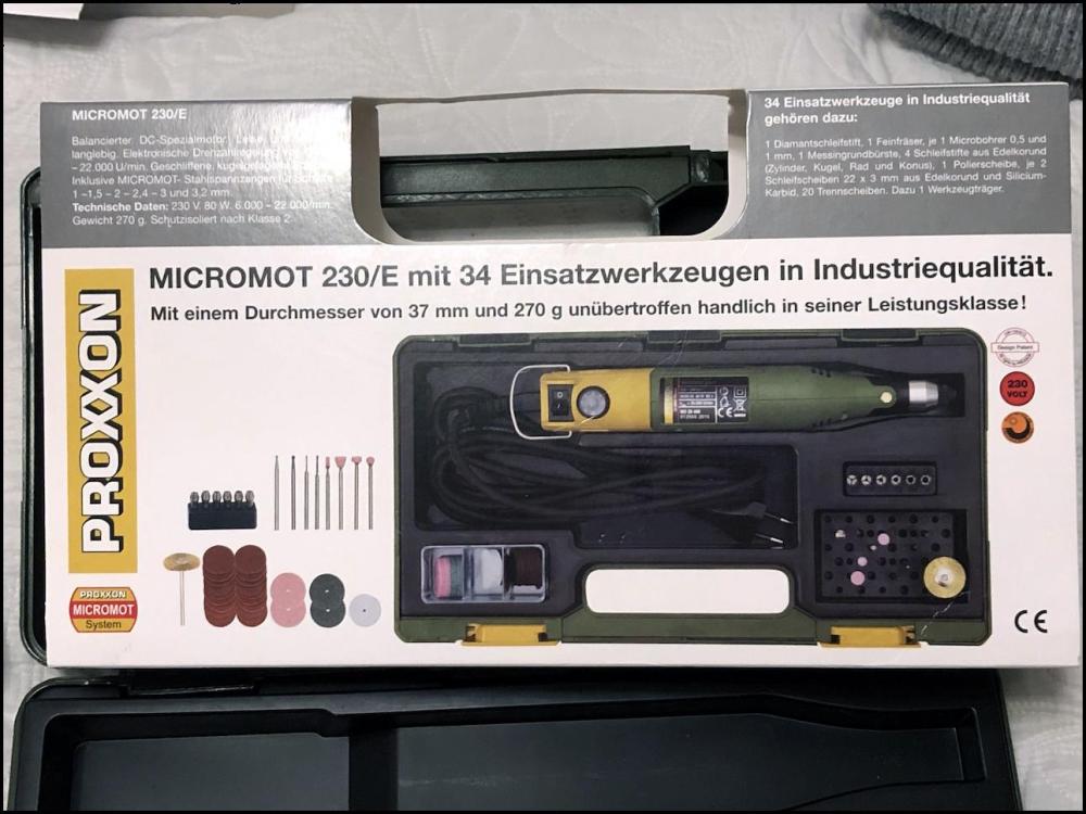
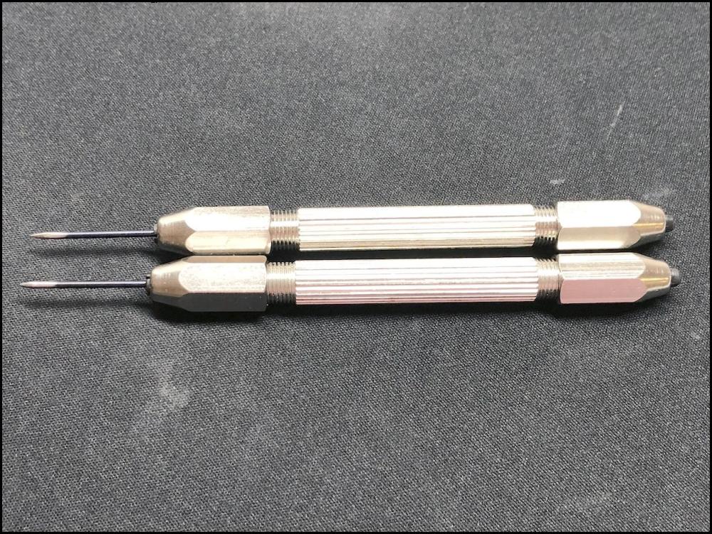
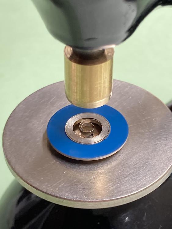
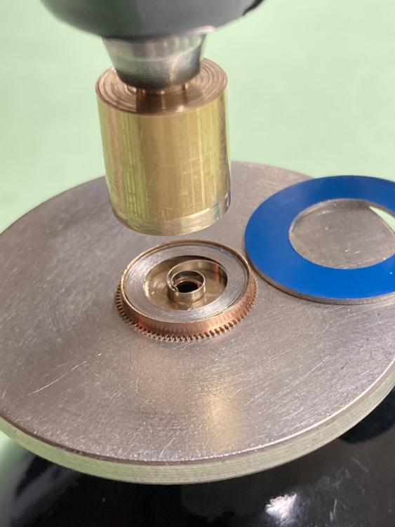
Inspired by the section (18:53) in the video, I’ve just made myself a pair of custom rods for manipulating anti-shock springs, etc., but in steel instead of brass. BTW, I do recommend the videos on the Macro Time Youtube channel. Excellent and entertaining! To minimize the risk of scratching anything, I’ve rounded off and polished the tips. I’ve avoided Seiko and Orient watch movements for several years now due to the difficulty of handling the nearly microscopic Diashock and Diafix springs for the escape wheel and third wheel. With these rods, I’m hoping it will become a bit easier. I’m really pleased with my work, even though I haven’t had a chance to test the rods yet. My only regret is that I ordered steel pin vices, instead of brass, as they feel unnecessarily heavy. On the other hand, they might be more stable in handling that way. We’ll see. To make the rods, I used the tools and accessories you can see in the pictures. The grinding wheels for cutting and rough polishing the steel were included with the multitool kit. Sweet! One thing I figured out this time was that I could use the sides of the felt mopping wheels. Very practical and probably obvious to most people, but I always feel so happy and almost surprised when I manage to come up with something on my own! Anyway, I hope you will find this post inspirational and useful!

 2 points
 -
The cracks are on the shellac only and it is not obligatory to melt it, seems to be good enough2 points
-
The results with the pusher are satisfactory. I’m not bothered about using a bit of brass rod- I’m fond of Omega 550 and the related 600 series movements, so this will get plenty of use. I’m usually successful with tweezers when fitting manual springs. But these automatic ones are something else. I might have a go at rewinding the bad ones using the washer technique, and then practice with a redundant barrel.
 2 points
 -
This thread, and the one quoted, have enabled me to successfully service my Omega Dynamic Automatic Chronograph. What a fantastic resource this site is. Thanks to everyone involved.2 points
-
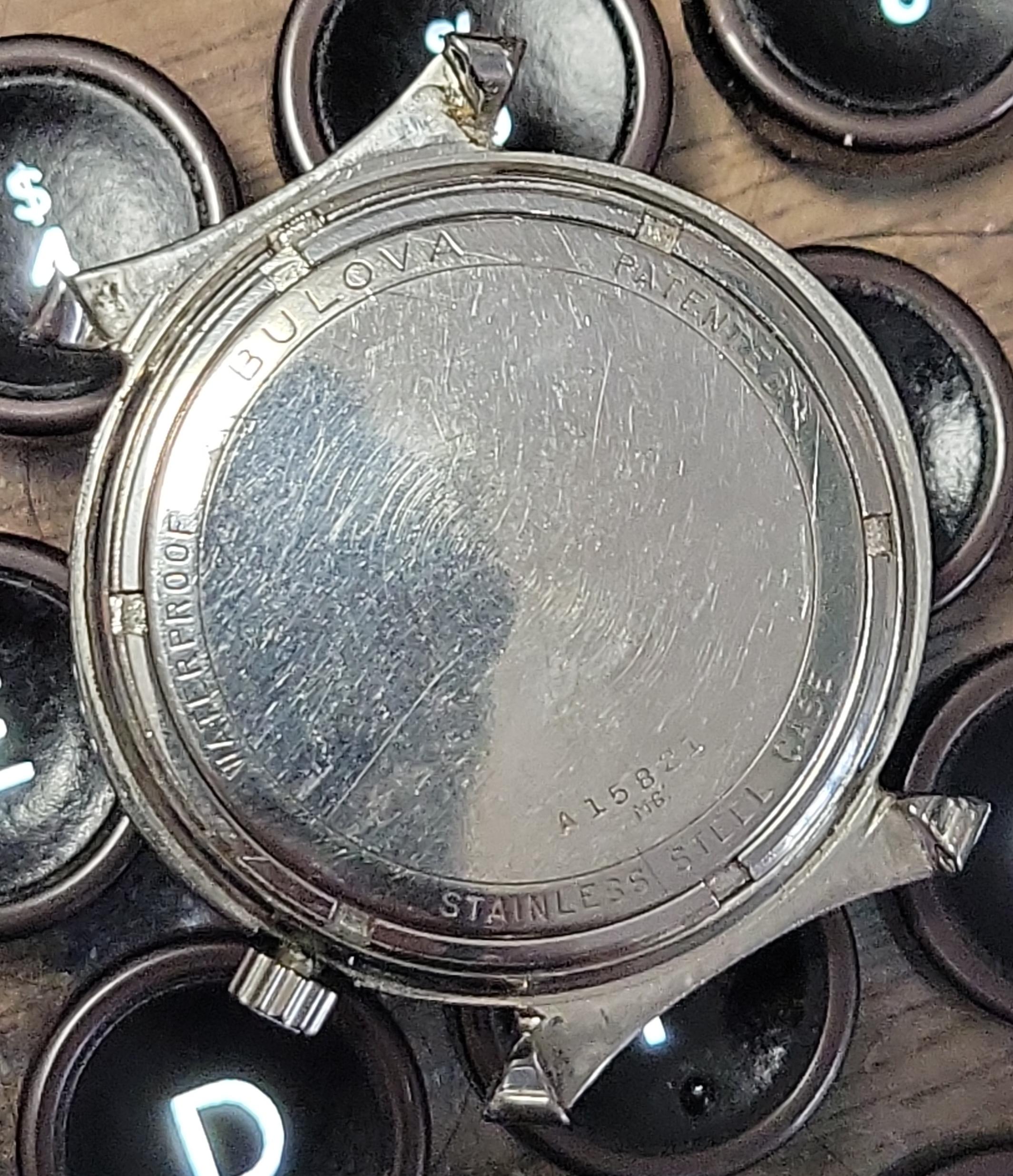
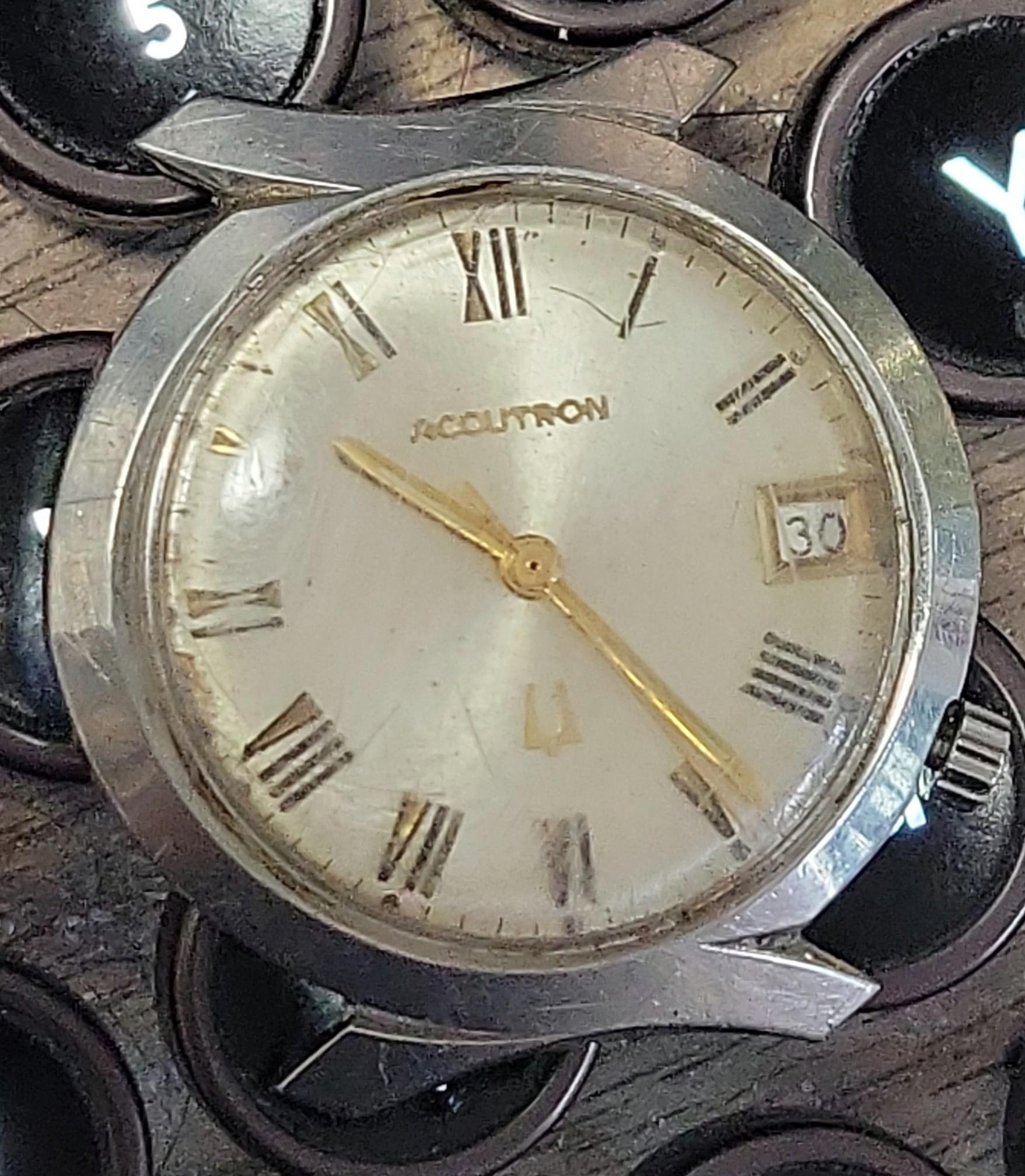
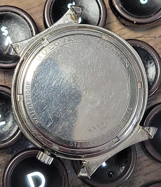
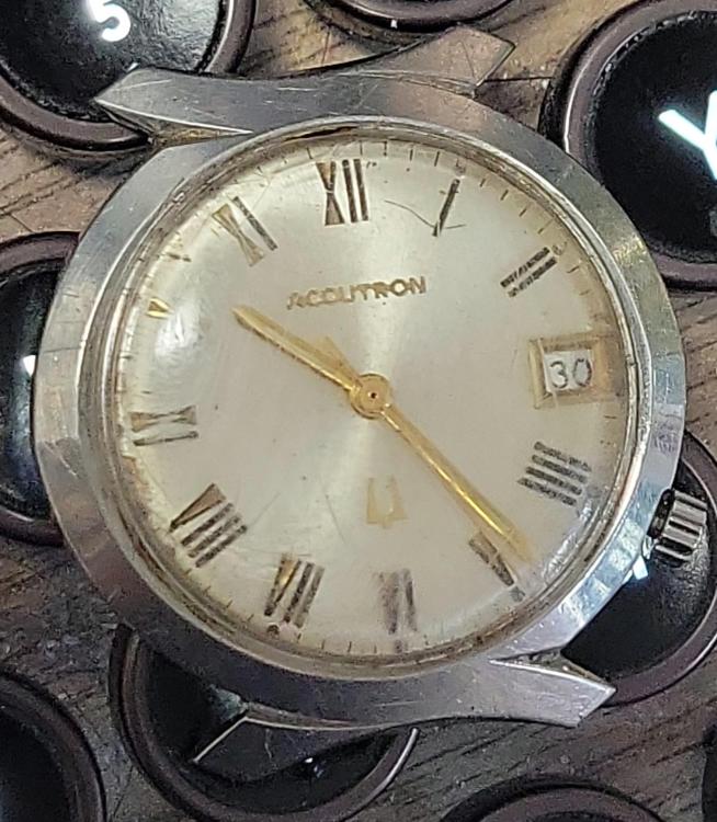
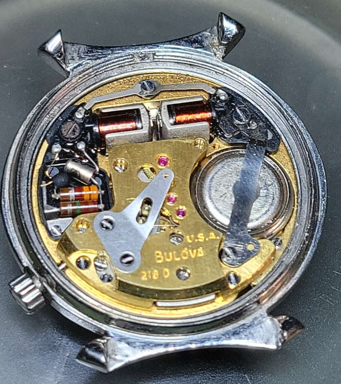
Lots of other things have kept me away from watches for a while, but I've been keeping one eye out for a bowtie case for one of my many, many 218 movements I've got kicking around, and this one came up at a price I couldn't pass up. Just arrived today. M6 date code, but I'm pretty sure the 218 wasn't released until 1967 so I'm not sure what I'll find inside. We'll find out together!
 2 points
 -
I can't see the issue, is there a chip or wear on the impulse face?2 points
-
Aye it certainly is Bill, some naughty monkeys and plenty of cheaters.2 points
-
No point messing around with spring bars as Klassiker says replace them.2 points
-
You first need to see this video. The stone You need is with specific shape and is identified with 3 sizes. The type is 'balance hole stone', the specific here is that hole walls are not cylinder, but have rather olive shape, or toroidal actually. One of sizes is the hole diam, the other is the outside diam and third is the height. The idea is the stone to get in the 'nest' in the plate when it is opened and the upper surface of the stone to be at some small distance from the end stone.2 points
-
I've had the same experience with my set. Also the rounded punches need reshaping because they are not rounded all the way to the hole. So the part that strikes the balance staff might as well be a flat punch. I'd like to try but would need some guidance from the collective wisdom here.2 points
-
When I first started and had problems pushing mainsprings out of washers, I too made a tool from some brass rod. Problem is you need the exact size for each mainspring washer. I found it wasn't useful, and much easier to push the springs out with some brass tweezers. The only problem is if the spring in the washer is too big for the barrel, as you have found.2 points
-
Last year or so, somebody found me and asked for help. May have been on this forum. They had an "accutron" that had been "modified." He wanted it returned to its former glory. Well, it was an accutron case, accutron dial, with an automatic wind movement inside!! Yes, it is true. The dial feet had been removed and glued on to the autowind movement with those dial dots. Anyway, I rebuilt it for him. So, you never know what is inside!!1 point
-
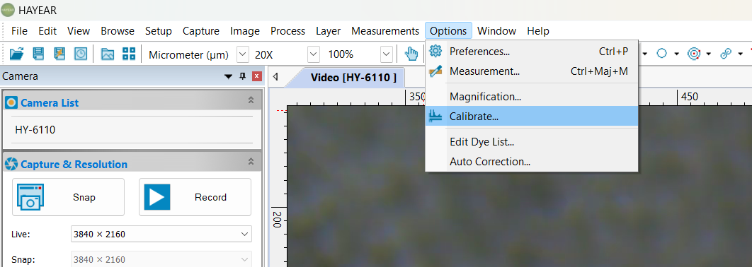
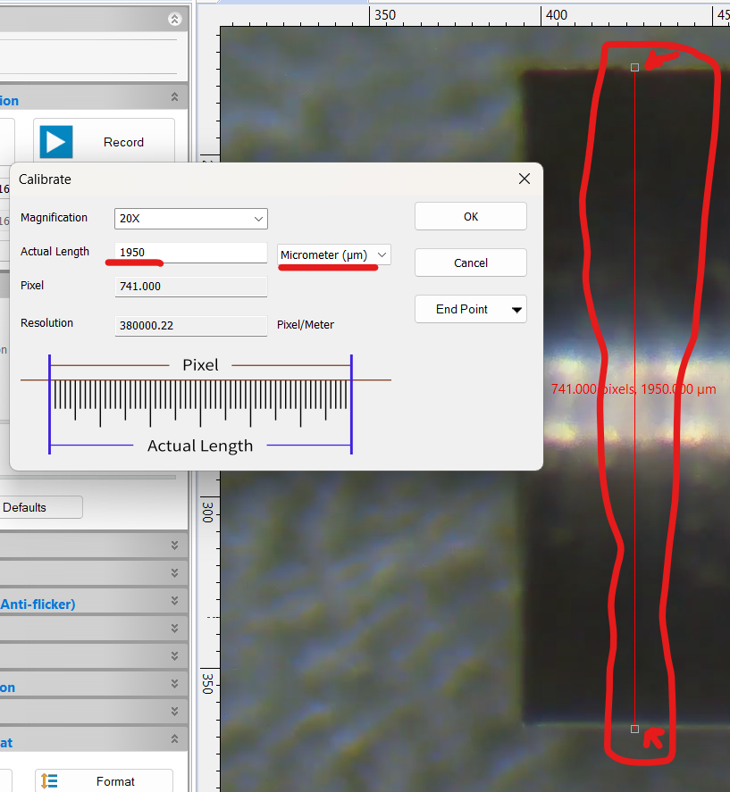
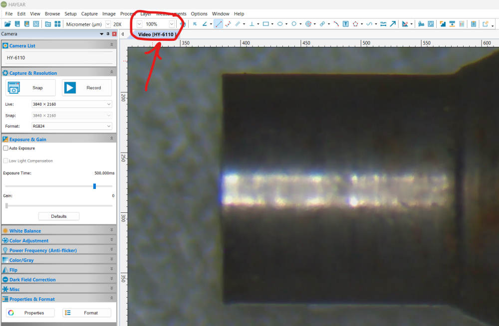
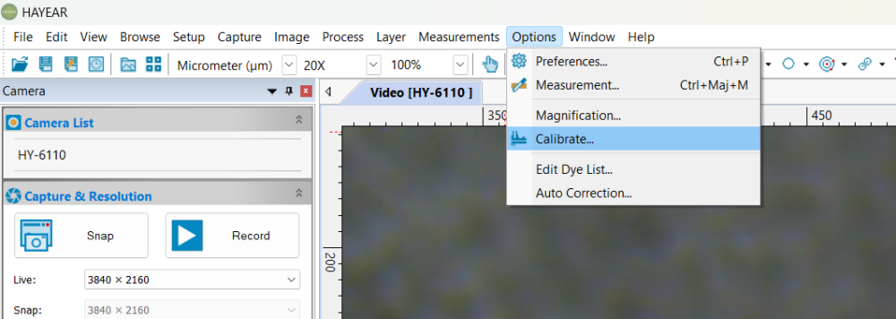
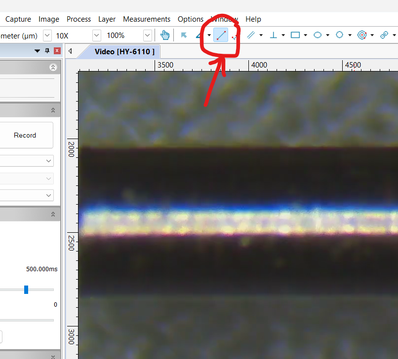
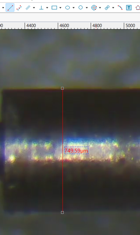
Hi all, As I am planning my first intervention on pallet jewels, I was looking into measuring precise distances with my Amscope microscope and Hayear camera. Since I hadn't bought the dedicated calibration slide for this purpose, I figured that it should be possible without. Here's a quick walk-through. 0. Switch on camera and put an object of which you know the exact size (to the 0.01mm at least). Ideally something as large as possible without exceeding the field of view (in the computer). I use a Seitz pusher that is supposed to be 1.95mm and use maximum magnification on the microscope. 1. open Hayear software 2. select 100% here: 3. Go to "Options" and "Calibrate" 4. Enter the correct unit and amount of the actual object. And draw the red line on the screen to match the respective distance. "OK" and done. NOTE: the "Magnification" field has no real importance since the camera software doesn't know what we are doing with the magnification handle on the scope. So the calibration is only useful at a given magnification level. Once changing the magnification on the scope, you will NOT be able to measure distances anymore. Now a test: This pusher is supposed to be 0.75mm. I select this symbol: Yep, that's pretty good

 1 point
 -
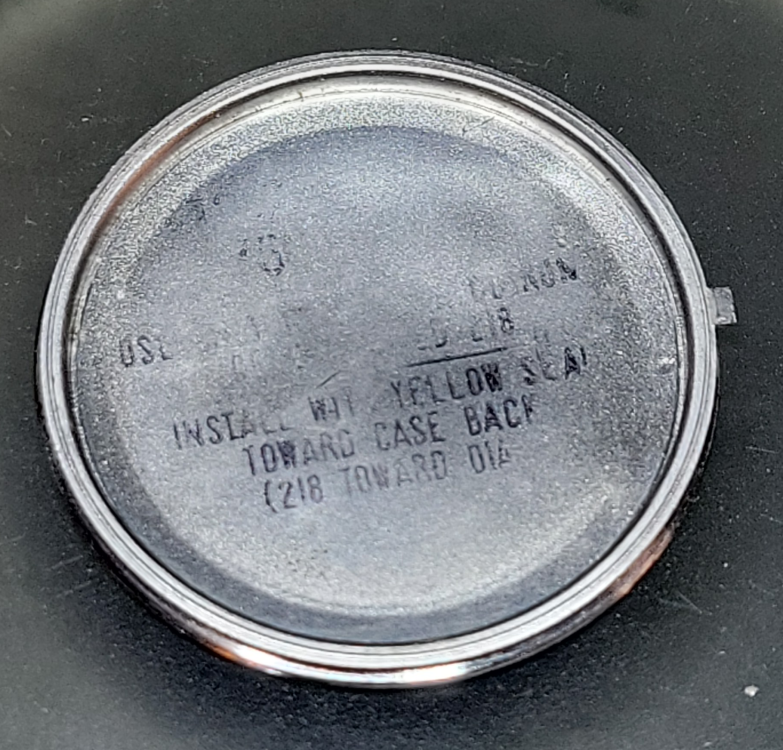
True, I just meant what kind of shape it'd be in. Looks pretty nice. I was wondering if maybe the caseback was taken from a different watch, but it is a 1966 Accutron caseback. Interesting! Edit to note of course digging a little further, I see 218s being manufactured as early as 1965.
 1 point
 -
Yup, the standards have gone down drastically Tom1 point
-
I thought EVERYONE is in IT or banking these days.1 point
-
Never been sure what the 25 stands for but as with other movements it could be a red herring. https://www.emmywatch.com/db/movement/benrus--cz/1 point
-
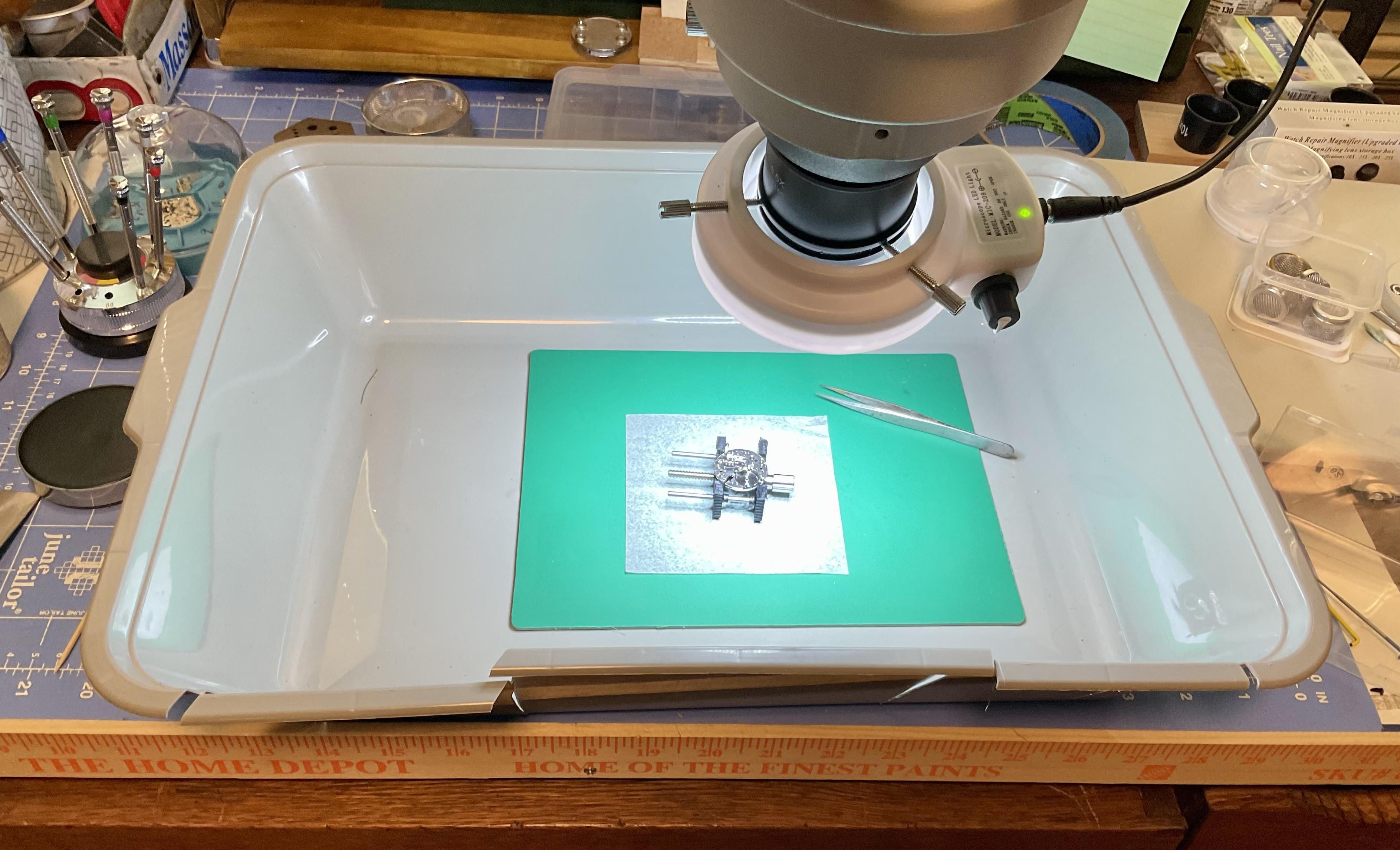
This new cat litter box fits nicely on my bench. Everything i need to do under the microscope can be done within the box. Here I finished oiling the Incabloc setting on an AS1187 movement, a small movement with tiny jewels which i have lost parts on before. Box was purchased at a dollar store for very little. I made cutouts for my arms but don’t use them. Parts that fly mostly stay in the box!
 1 point
 -
Are there any markings, under the balance or behind the dial?1 point
-
The museum of timekeeping has all the speaking clocks. I believe it's still available but is just a computer these days.1 point
-
How accurate do you think your measurements are? For the Hour you should be OK with the 2mm. For the Minute you could go for the 1mm are reamer it out as long as there's enough body or the 1.15mm with the intention of closing the hole slightly. That's all presuming they're long enough?1 point
-
@Roll1ex FYI, so I'm getting 100% power reserve after about 15h of wear. Probably around 6k steps. I guess that's fine.1 point
-
As you are in the US then the Horolovar company is the ideal place , they may even have I complete torsion spring including top, bottom, blocks & fork if you want to go that route, at the very least they may be able to tell you where to add the fork. Good luck Dell1 point
-
I wonder if it can be heat treated to harden it.1 point
-
This is what I supposed, but you are the first to confirm. Seems all the other buyers of this tool keep silence about it or just use it for display?1 point
-
Sorry but, I no longer take on outside work.1 point
-
I also live near the see and it is humid here. I have dehumidifier in every room and they work non-stop all seasons but summer. I drain in the sink 3-5 liters of water from every dehumidifier every day1 point
-
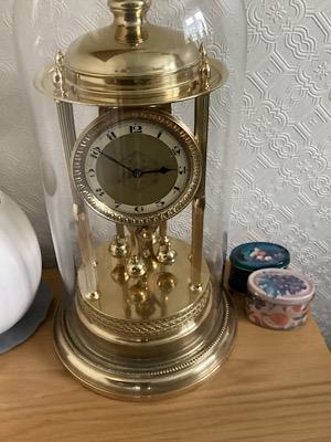
The book doesn’t give measurements for a lot of clocks including GB’s I start by fixing top block & hanging it on the saddle then put pendulum on something on base approximately 1/4” (6mm) thick then cutting the torsion spring 1/2 way between hook on pendulum that will give you the correct length but the fork position is trial & error I am afraid but try to start a bit to low as with the fork to low there is more chance of it running than when to high I usually start with the fork just below 1/2 way between top of backplate & top of saddle, if you get fluttering (escape wheel dropping more than one tooth as a time ) then raise the fork by 1/2 to 1mm until it stops fluttering, don’t worry about time keeping until the clock runs. By the by make sure you get a long torsion spring because most places sell standard length but for a bandstand you need the longer one, what part of the world are you in because then I may be able to tell you where to get torsion spring from. Here is a picture of my Kern & sone bandstand. Dell
 1 point
 -
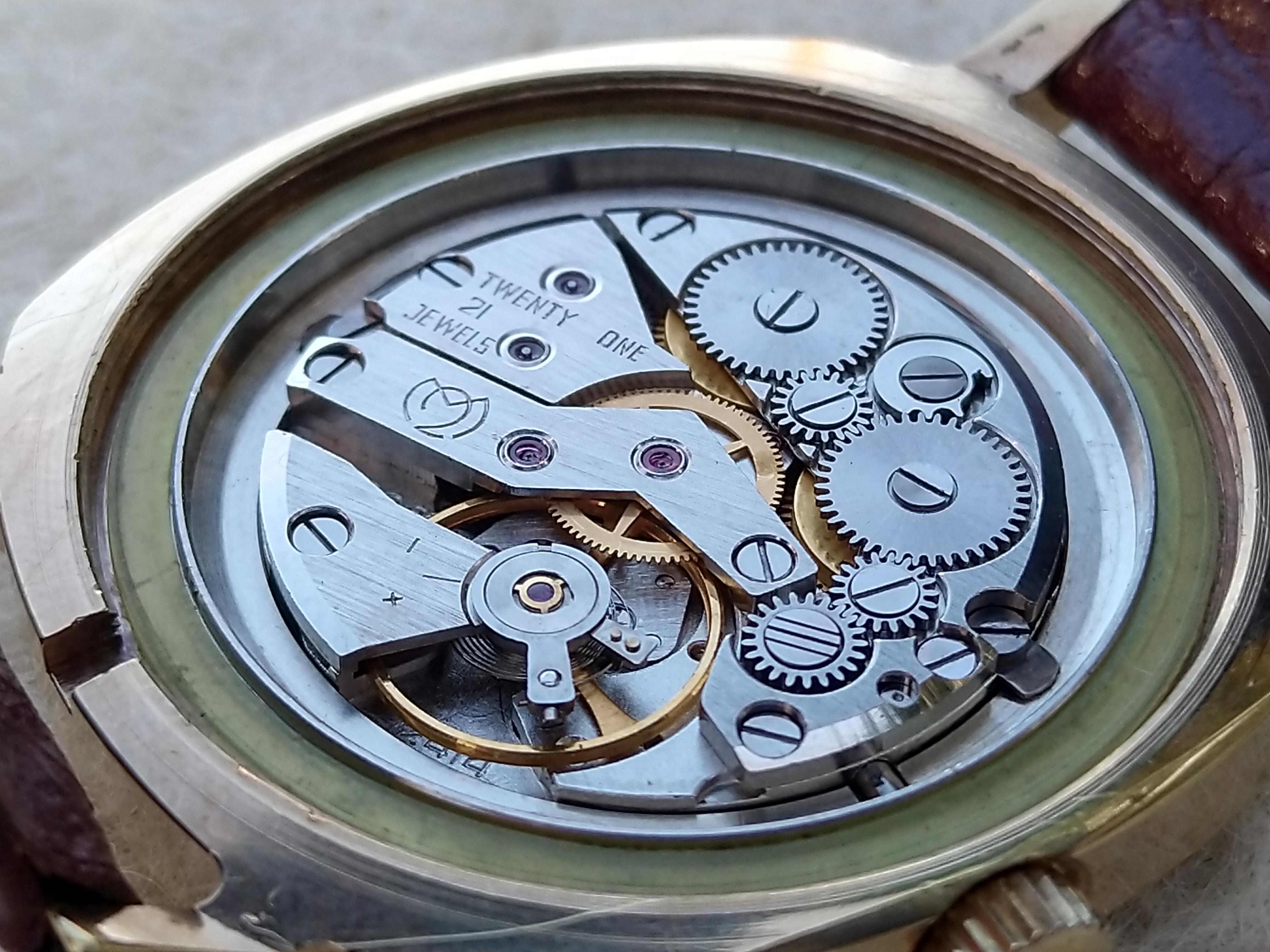
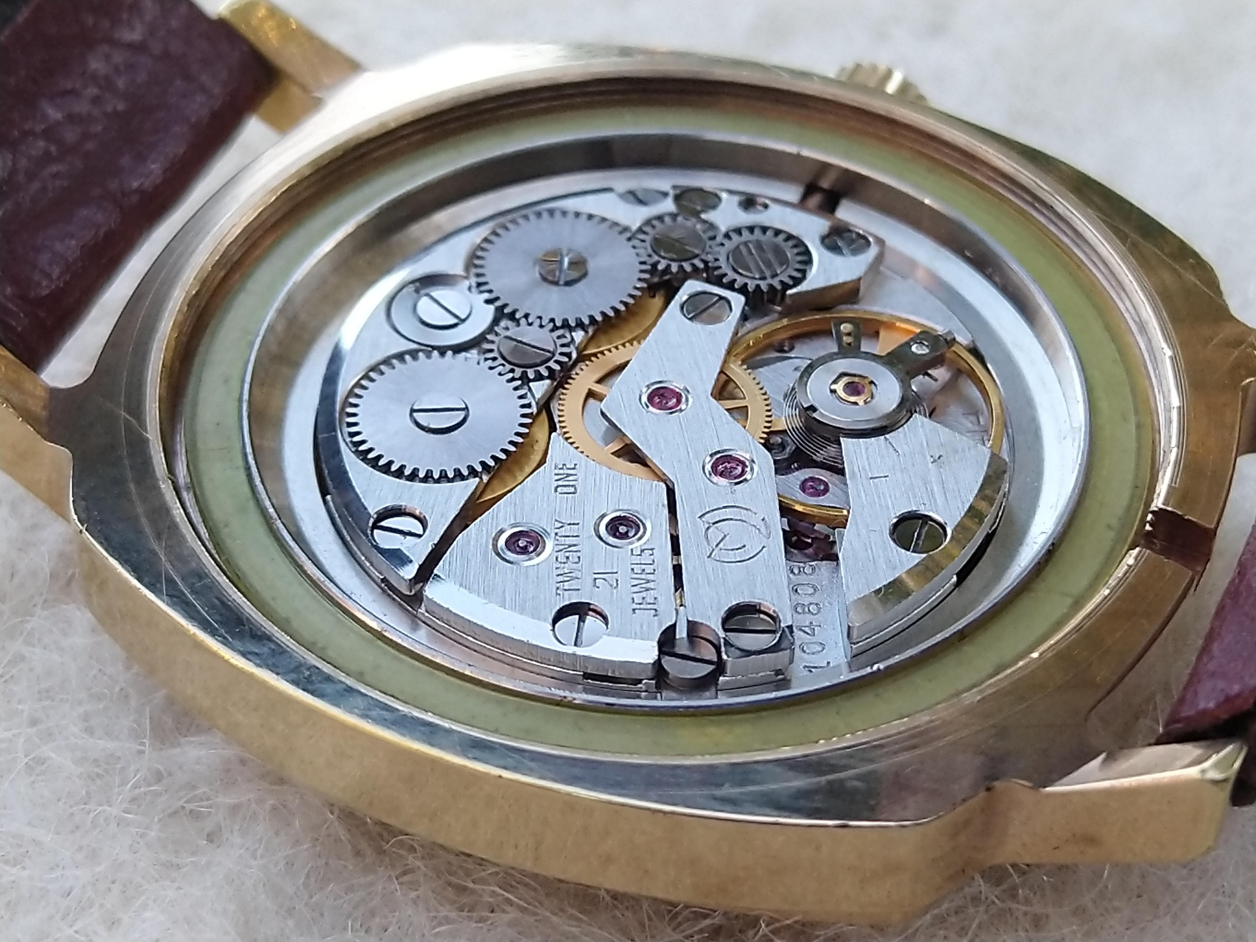
HWGIKE#39 Slava 2414 Russian bi-turbo movement. Full service very nice performance. Managed to cut the hairspring at the stud by accident, luckily it was long enough, nice straight line around zero beat error, amplitude around 320. Also lost one of the MS arbor, but found it after a bit of carpet surfing aaand I put the MSs back into the barrels the wrong way.... Kept the strap, its fitting.


 1 point
 -
Hi KB2025 & welcome your bandstand Gustav Becker like all GB’s are supposed to take 0.004” torsion spring but all the GB’s I have had to have a thinned down 0.0045” , Gustav were notorious in that they had only half the serial number sometimes and other stamping all over the place , I think being a bandstand it was probably made in the 20’s. The most important thing about a torsion clock is it has to be as friction free as possible as it needs to run for a year so it will need stripping, cleaning including mainspring removal, use oil to lubricate mainspring not grease, here is my video on how I thin a torsion spring also some of my other videos may be helpful. All I restore is torsion ( Anniversary) clocks if you need help just shout. Dell1 point
-
I would place the balance complete on a balance tack, and remove the balance wheel. Is the hairspring not held on the stud with a taper pin? Id try to leave this stud in, as setting it back to its original height might prove difficult.1 point
-
Thank you, that's nice to hear. Considering a month ago I literally had no idea how a watch worked (I assumed there were maybe 4 times as many parts ) I think its going ok. Buying a microscope (cheap £60 prior long arm from Facebook marketplace) really helped. I wasn't intending to get this deep into how they operate this quickly, but yes, it's forced me to learn, which is exactly what I enjoy about a hobby. It's alot less messy than rebuilding engines and gearboxes too. My tweezers skills have improved loads and I'm amazed I haven't broken this hairspring yet. This watch has been a great starter I think as it's not been a case of just replace a broken bit and it works. It's forced me to learn how to assess each aspect. You folk on this forum have been a godsend. I am very grateful for everyone's help. I also feel it's my responsibility to repay that help by succeeding. I'll get the amplitude back. I had 270 out of it before I took the escapement apart again. But it is basically full of dirt and no lube again now, so it's to be expected I guess.1 point
-
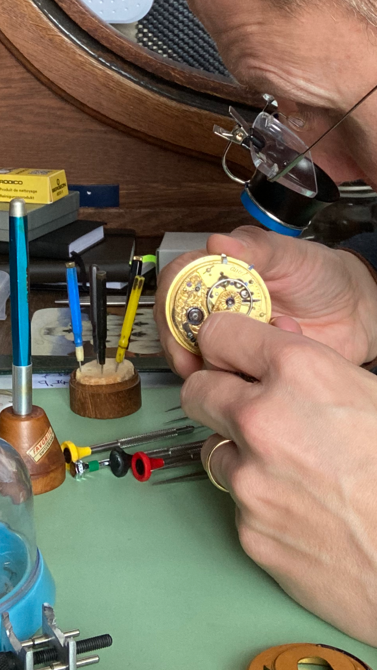
OK, it is good to understand the maths, but this is of no big use when real poising needs to be done. The others in the thread give good advices, but I will try to summarize all shortly. You don't need to fill all this tables with the rate data in 8 positions. Finding the heavy spot is easy - by slowly rotating the movement together with the microphone, You find the exact position where the rate is fastest while amplitude is about 150. You don't care if it is crown up or half-norhteast or whatever. Then You stop the balance, bring it to neutral position and the heavy spot is down, under the balance staff. If You are afraid to forget where the heavy is, then put a dot with marker. Of course, You have already seen how big the rate differences are, so with the experience gained, You will be able to suggest how mush material You have to remove or add. In beginning You will make small changes and checks. Knowing the rate in horizontals, You decide to remove or add material. Now, If You deal with some Patek or Vasheron with golden screws, this is another business. Here You have simple and not expensive movement, so filing the screws is not a crime. But better choice is to drill holes in the heads with half smaller drill bit than the screw. No timing washers - use timing wire. Simply untighten the screw, make a wind of thin copper wire under it as the beginning and end are on the bottom side, then tighten the screw and cut the excess with office knife. Static poising helps to shorten the process when the differences are big. No poising scale - use tweezers. Of course, You can skip static poising. Have in mind that when differences are not big, the dynamic poising can be done by bending internal curve of the hairspring only, thus moving the center of mass of the spring relatively balance wheel .1 point
-
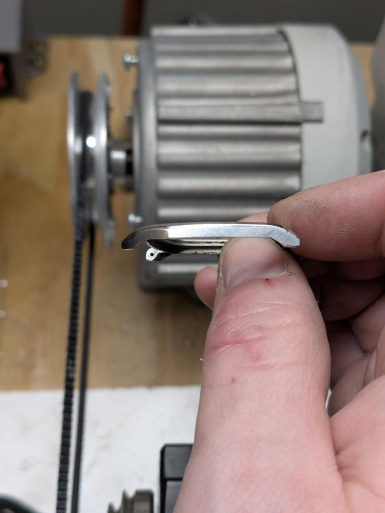
See, what You describe seems like rotor short connection. If You assemble the motor and measure the current while it is rotated at full power, it should be much smaller (no load) than what is written on the motor plate. If no current is written on the plate, then the power should be written, divide it by voltage (220 or 110, which part of the world?). If the rotor is shorted, the current will be much bigger. In such case, just search for another suitable motor, it should be no problem to source one.1 point
-
It looks a bit like there may have been a trace of oil on the brushes? That could cause smoke. Also, is the insulation between the commutator segments flush with the copper? It should be slightly undercut so the brushes are not lifted from the segments, as that causes arcing and wear. If it is flush, you can use a junior hacksaw blade to cut it in just a quarter millimetre or so. Deburr the comm with very fine abrasive sheet afterwards. This info is about DC motors, but the principle is the same - just a shallower cut for a universal motor such as yours. https://www.waiglobal.com/media/wysiwyg/1104-01-WAI-US-DC-Motor-Undercutting.pdf1 point
-
This is one of those tools that I appreciate the most. I now have two sizes of this tool (1.0 and 1.5 millimetres), which cover most of my needs. There is at least one interesting and entertaining thread about these tools: "Barrel Arbor Holder vs. Pin Vice"1 point
-
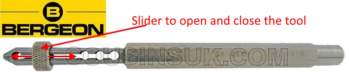
Yes. This procedure resulted in one of my most spectacular, heart-stopping accidents in watchmaking. I was struggling to remove a particularly stubborn arbor from from the barrel and the mainspring decided to fly out of the barrel in one direction, while flinging the arbor in the opposite direction. I stopped and listened carefully to the ricochets to echo-locate where the parts landed. By some miracle I managed to find the arbor. There are specialized arbor tweezers by Bergeon for this specific task, but in typical Bergeon way, it comes with a ridiculous price and several sizes. I modified a couple of cheap pin tongs from Cousins to grip the arbor and safely remove it from the mainspring. It sure makes the task less daunting.1 point
-
I have a Ø1.50mm Bergeon arbor holder and I absolutely love it. The 1.5mm size seems to be a decent fit for most normally-sized movements, but would probably be too large for a lady's movement and too small for a large pocket watch. I asked Alex at the Watch Repair Tutorials YT channel what size he would recommend and he replied: "The size I use almost at the time is the 150.", so that's why I decided to get the same size. Here's the video where he's using it and you'll find Alexs' reply if you look for it in the comments section. The arbor holder is much easier to clamp onto and release from the arbor (look at the picture). Also, it dramatically improves seeing what you're actually doing while removing and fitting the arbor from and into the inner coil of the mainspring. The head of the pin vice is most of the time so large it covers the entire arbor - and more - making it quite difficult to see what's going on. Absolutely not! It's just a whole lot less convenient in my opinion. None that I'm aware of I'm afraid, but we have some experts on Chinese watch tools on the forum so hopefully they can shim in!?
 1 point
 -
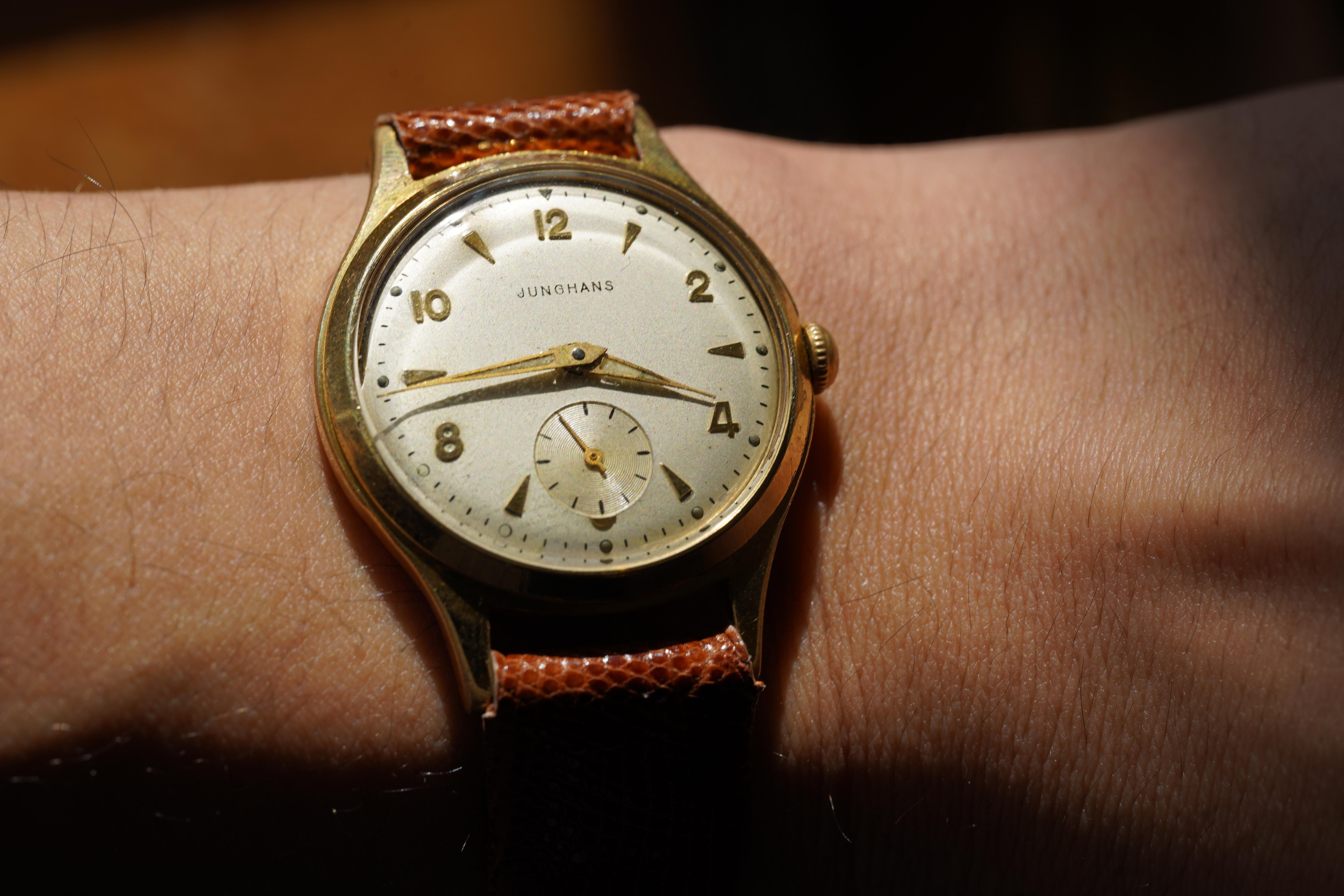
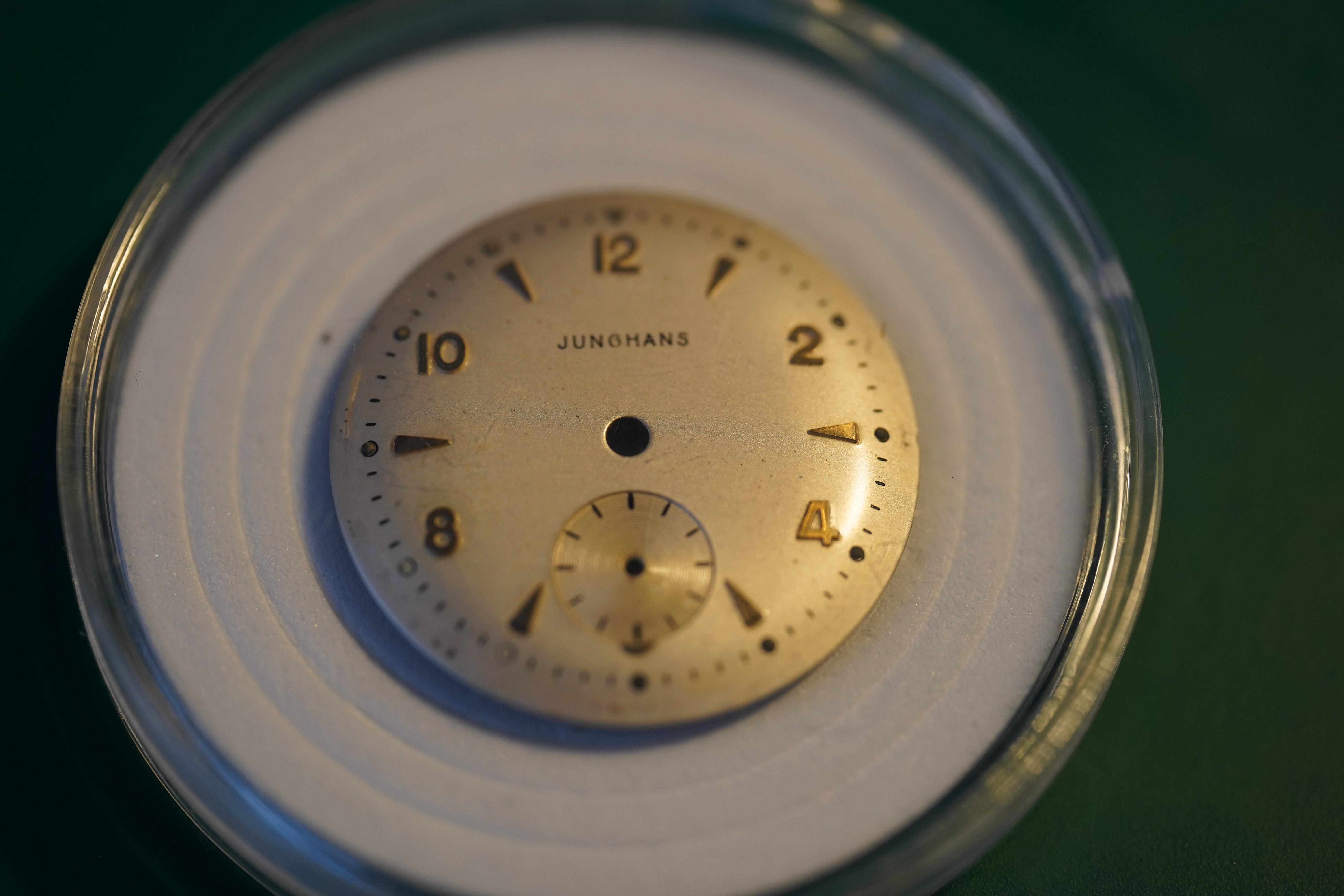
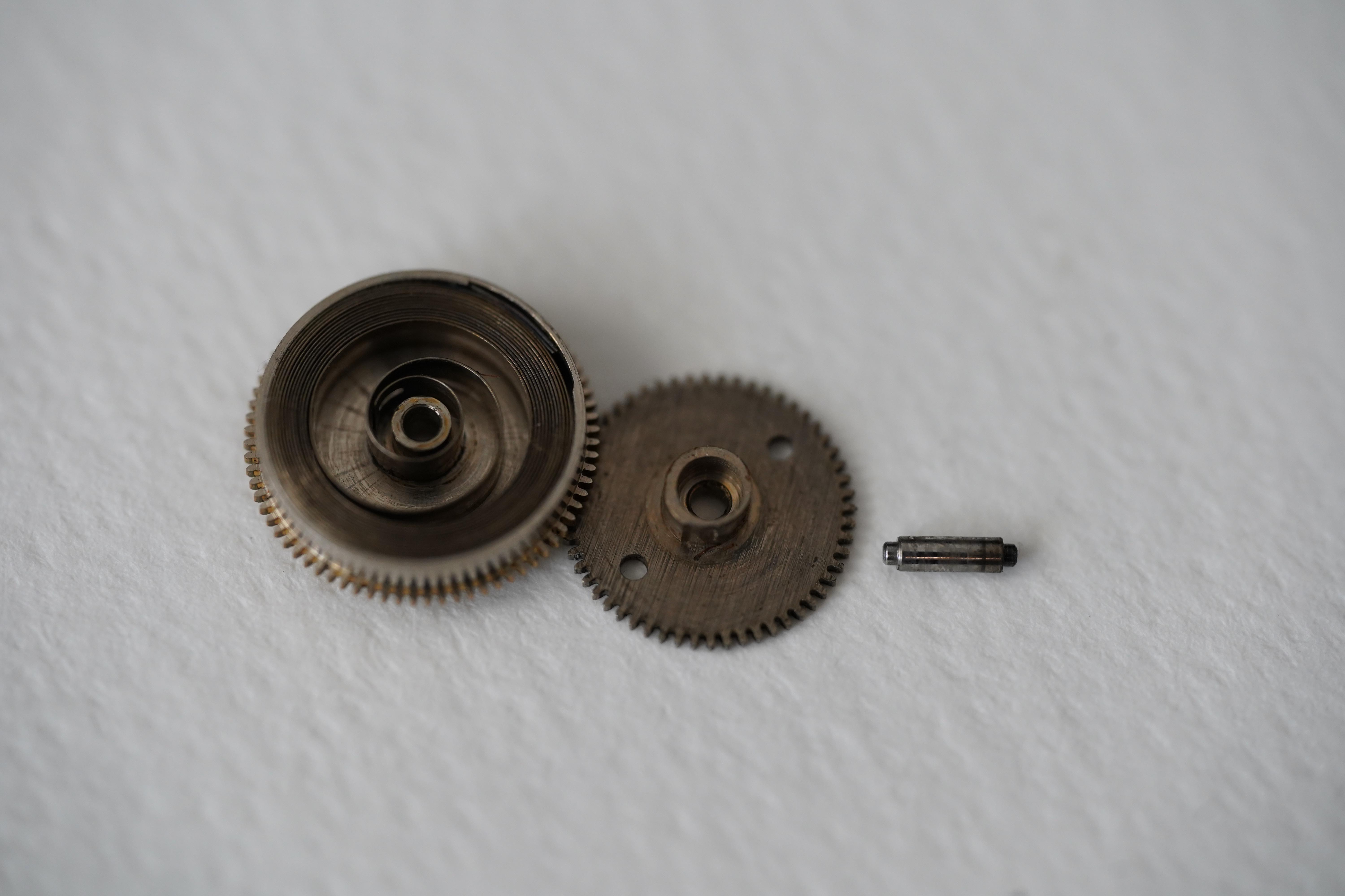
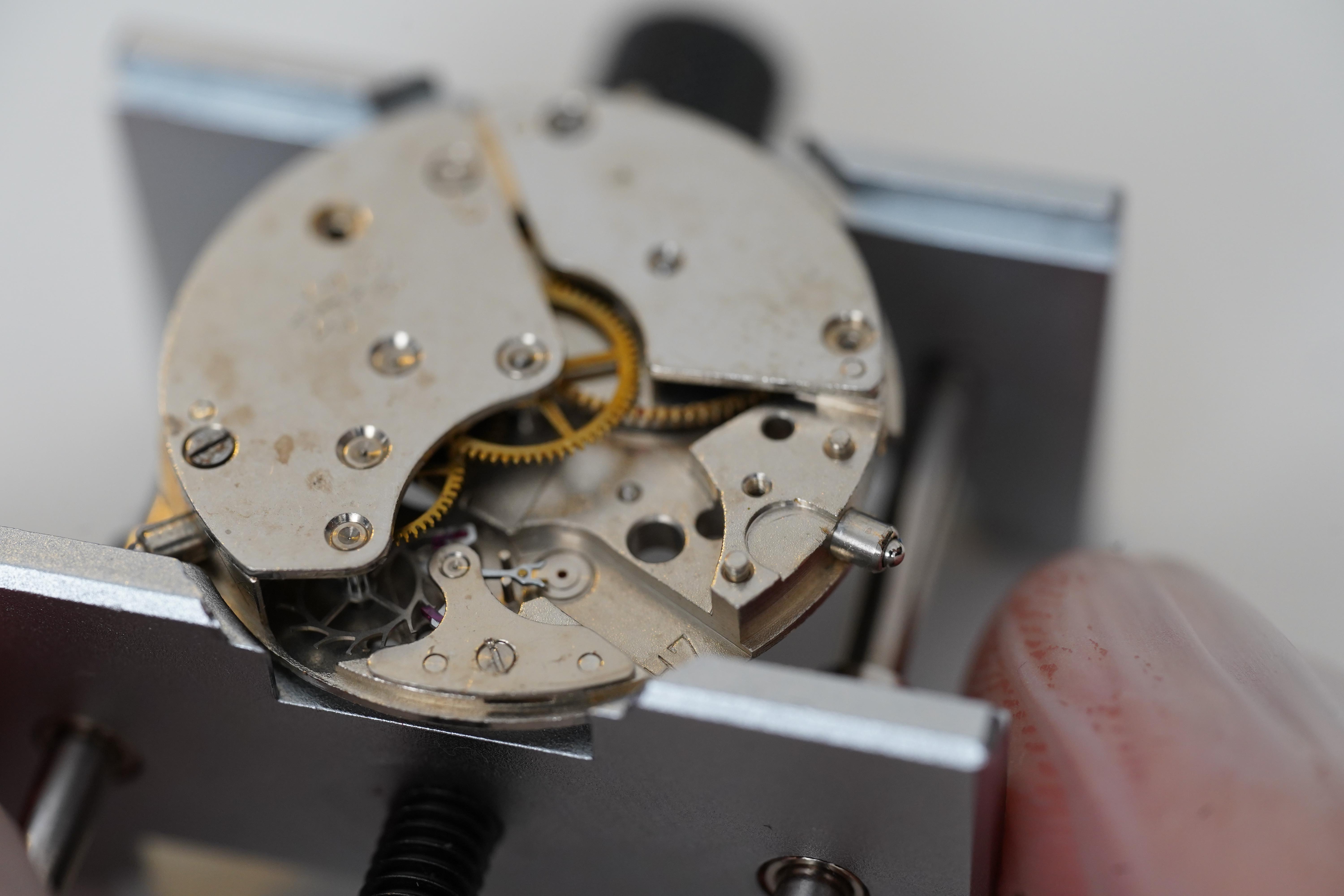
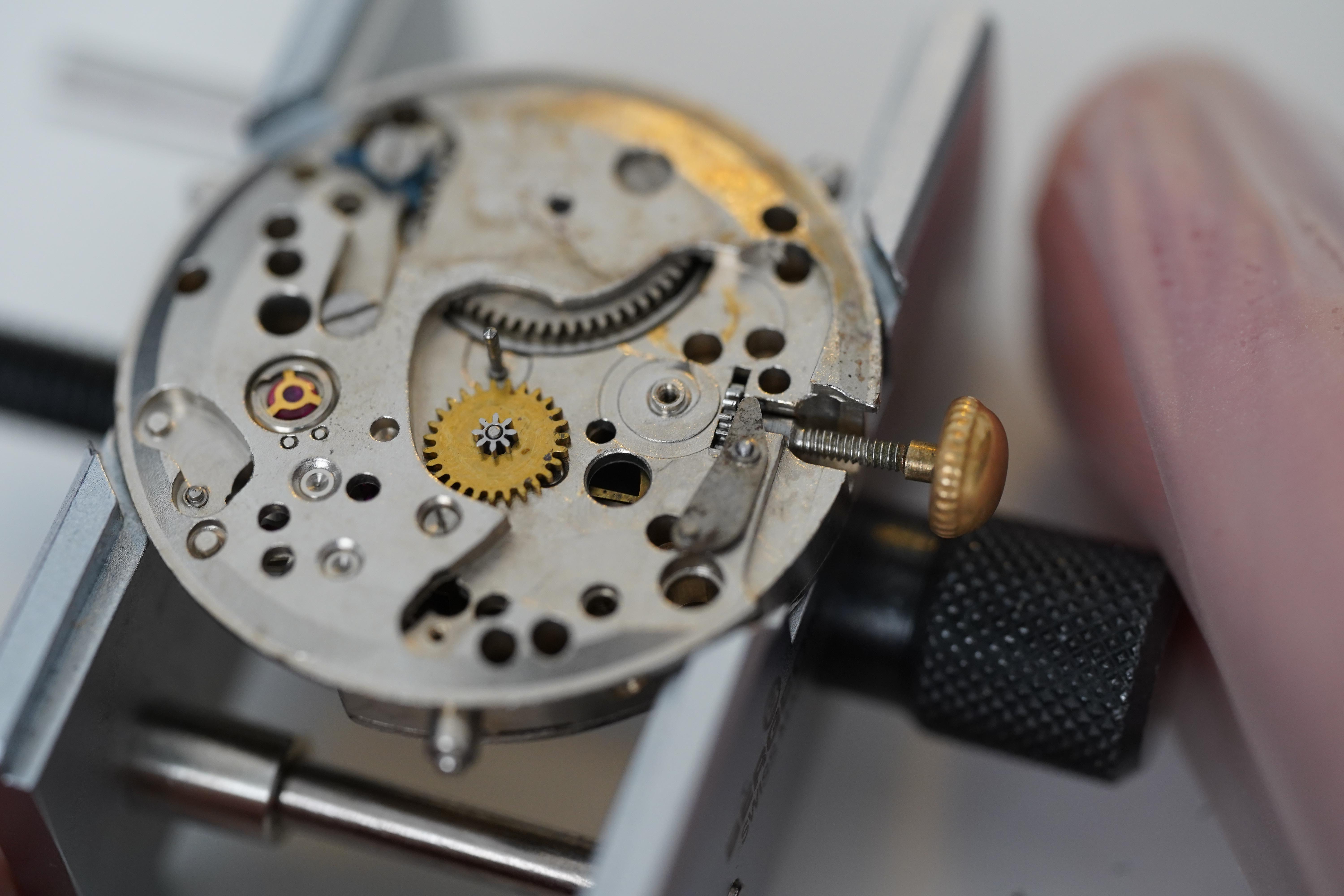
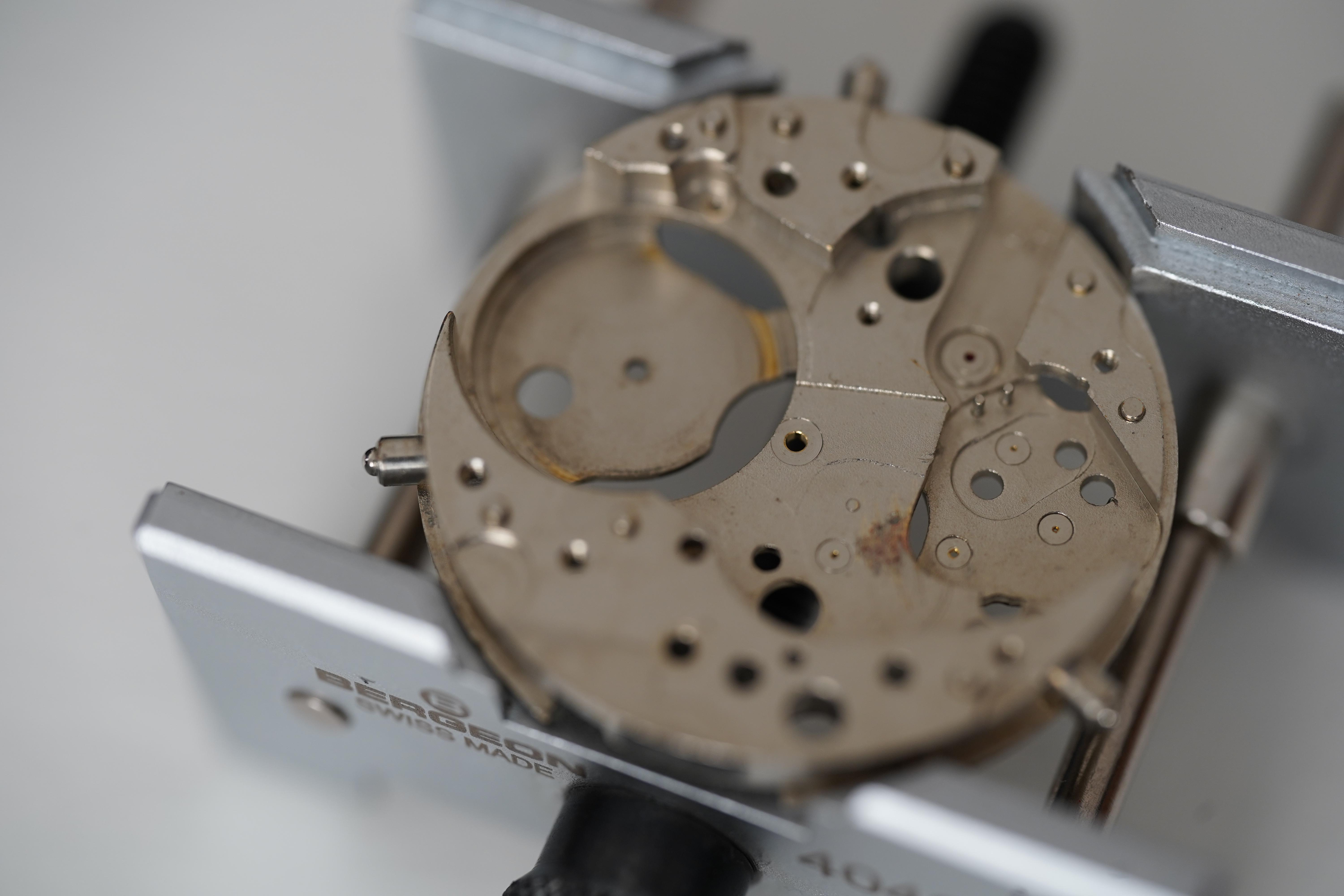
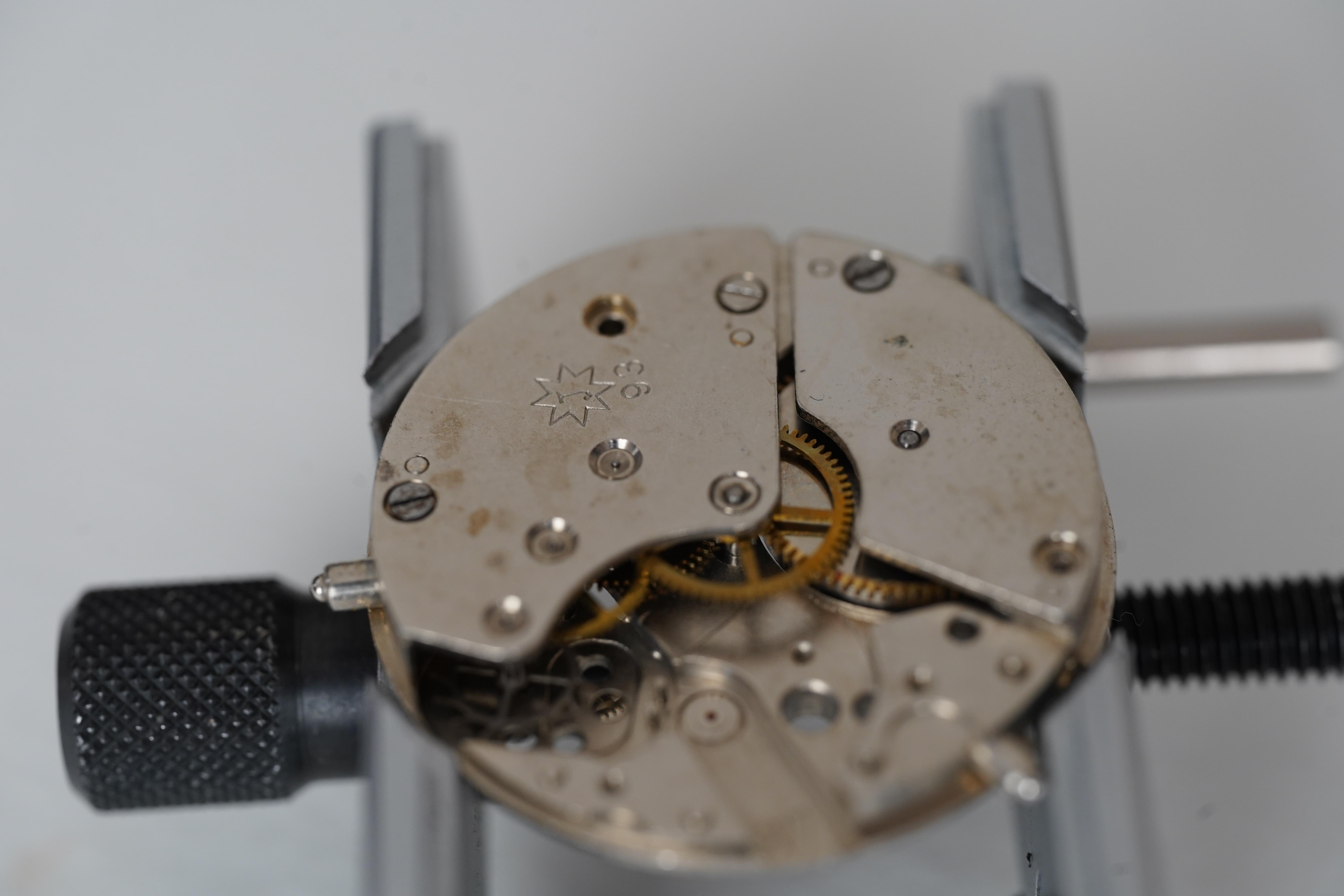
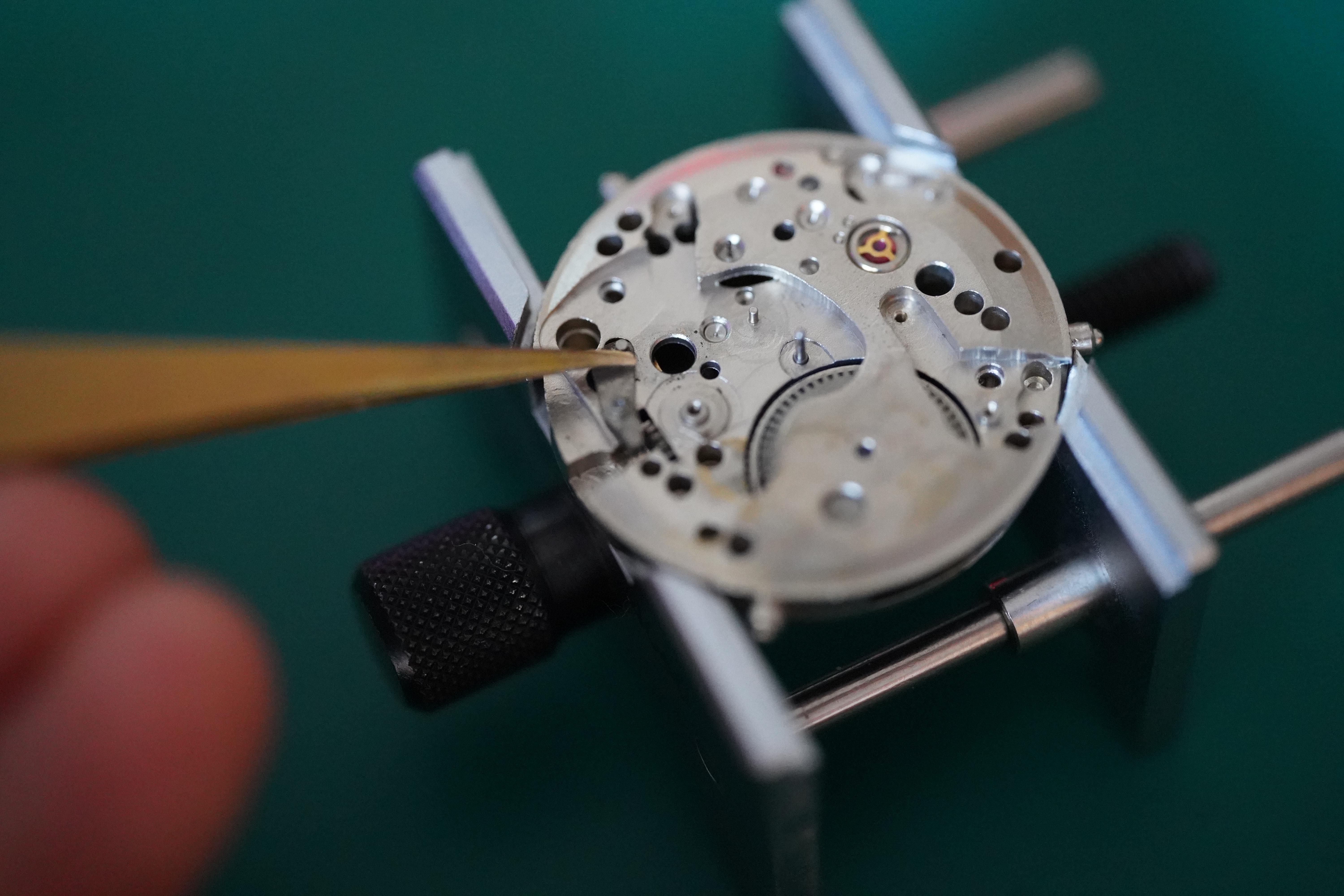
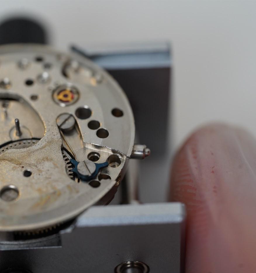
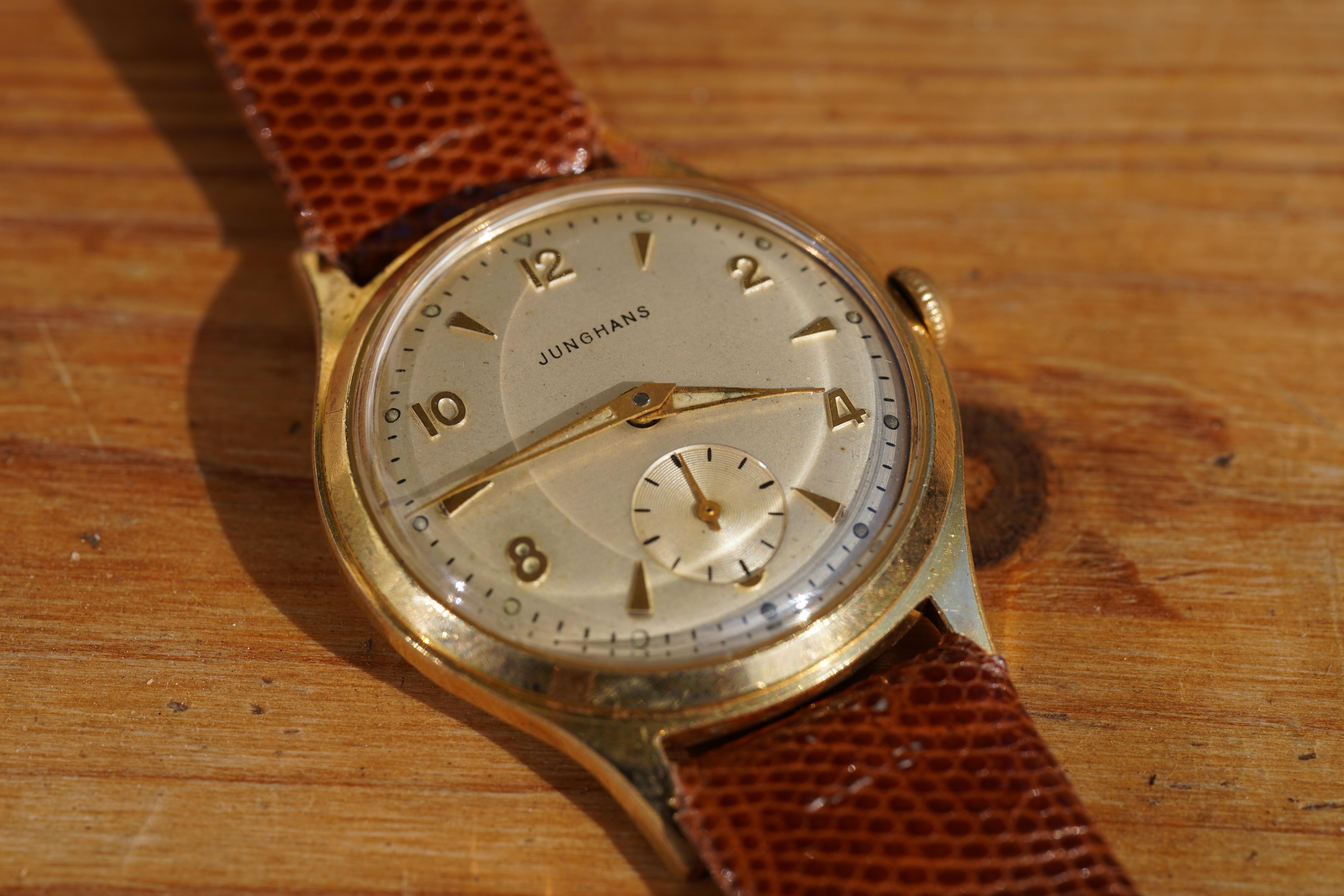
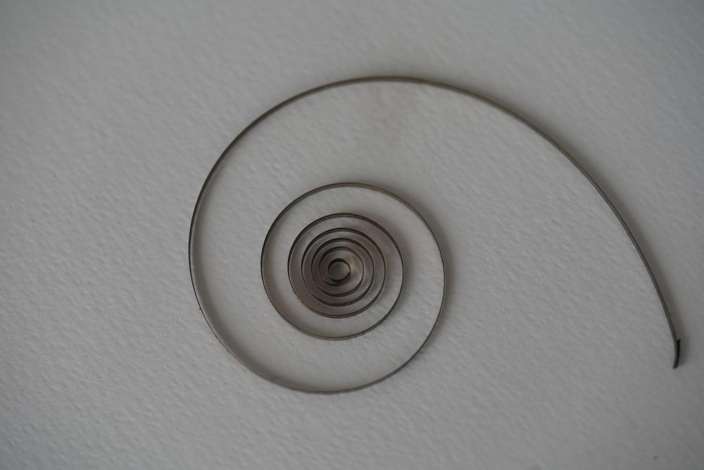
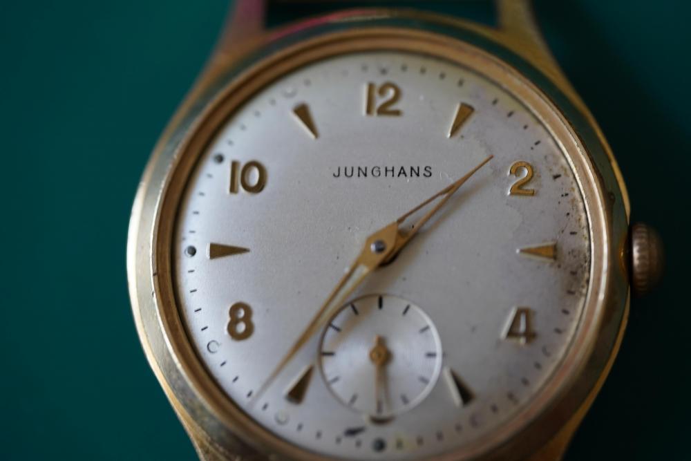
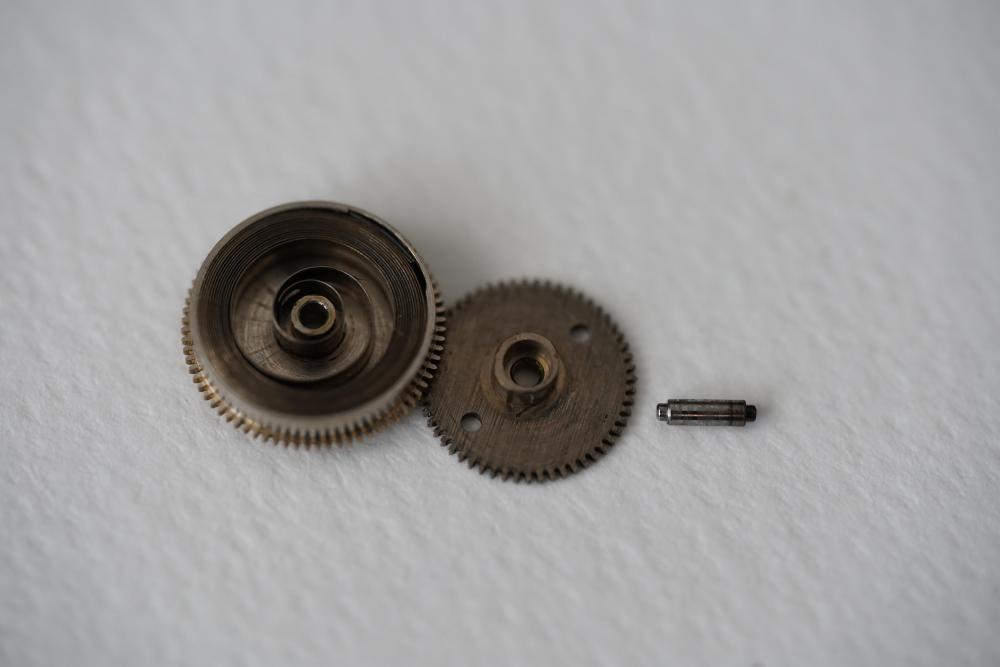
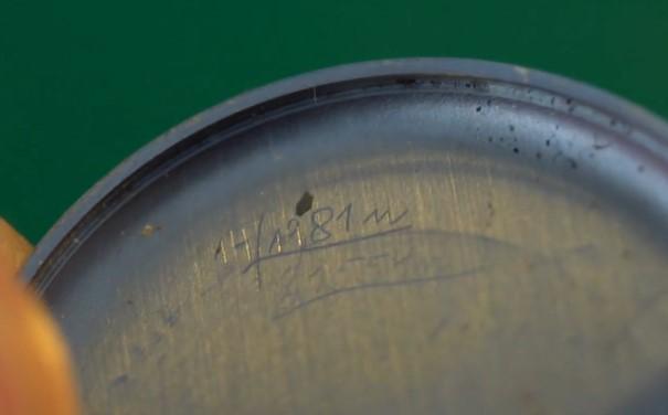
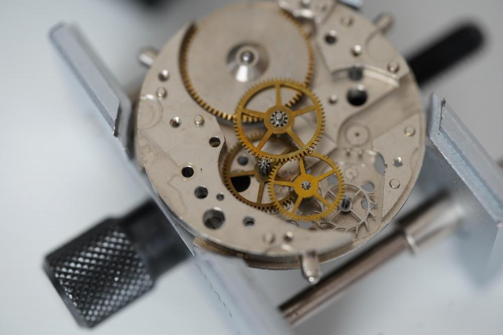
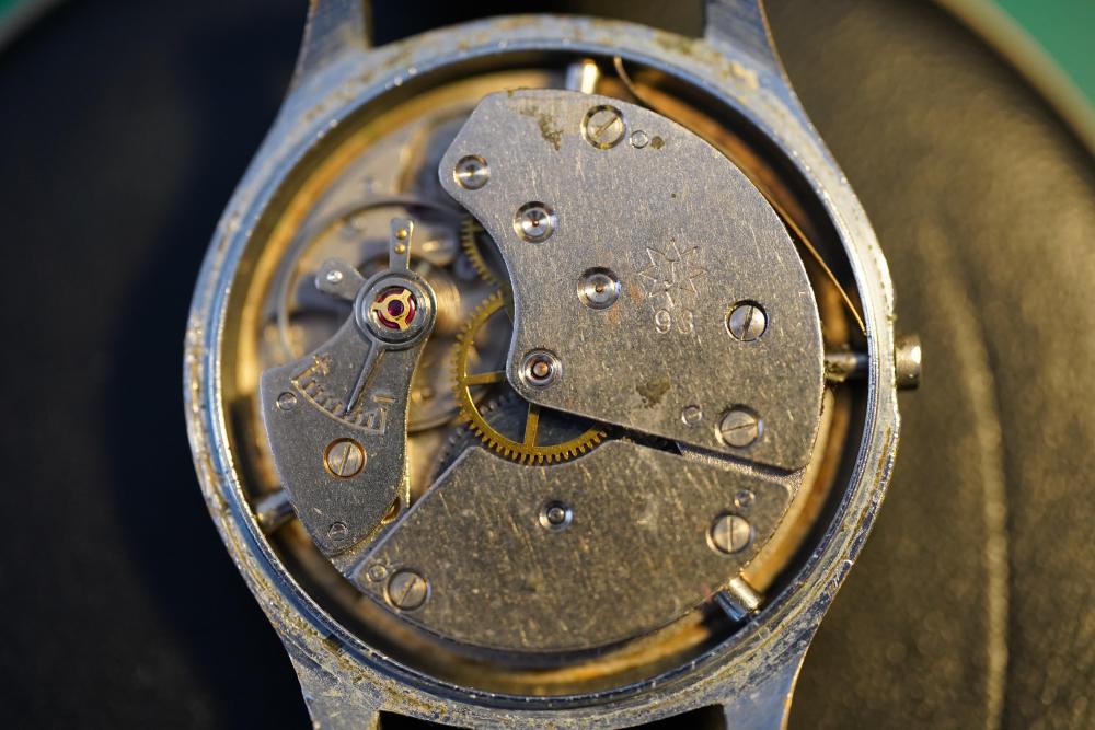
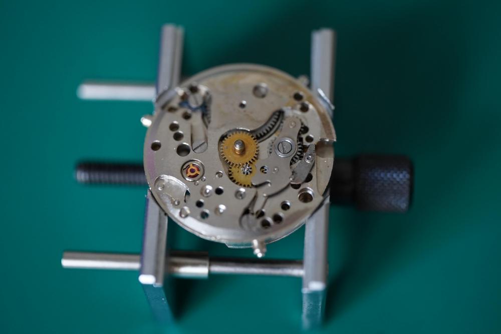
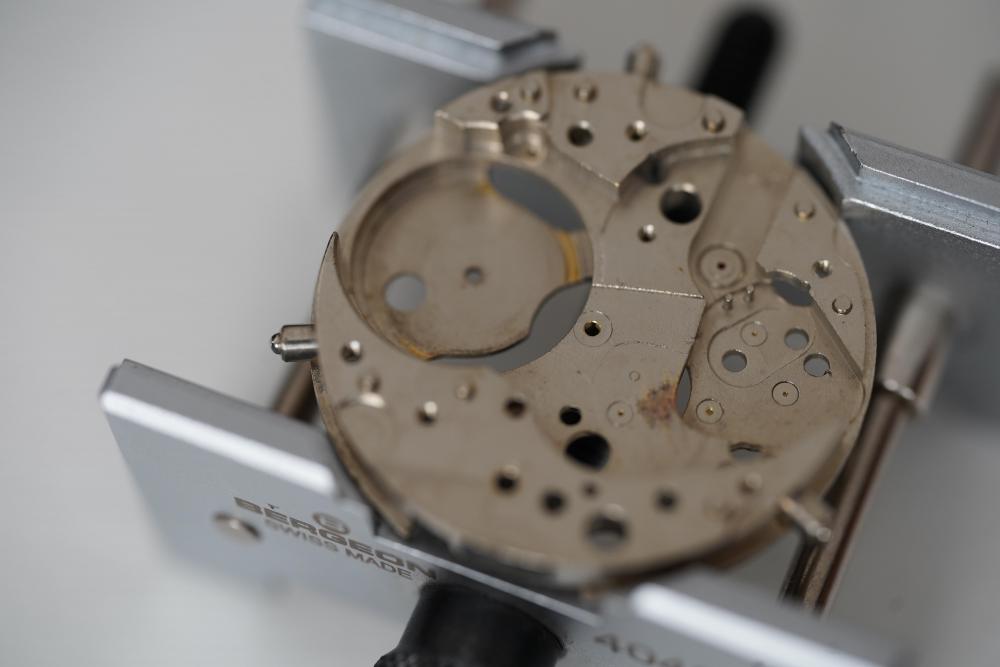
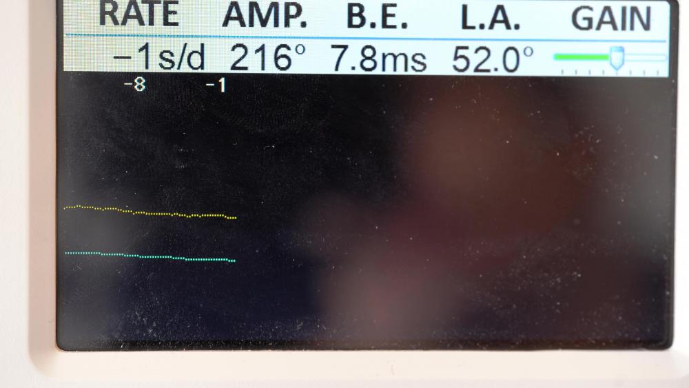
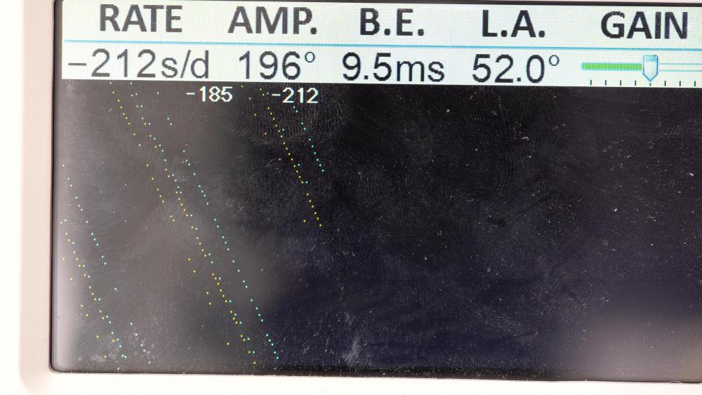
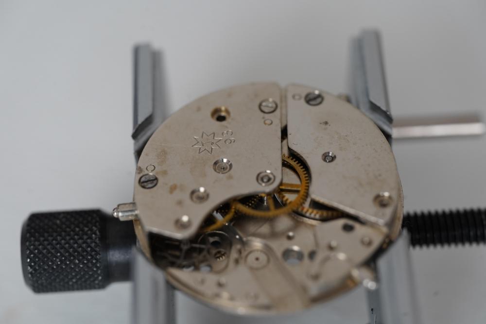
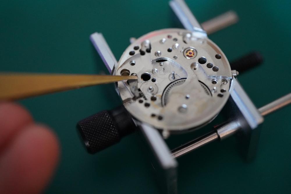
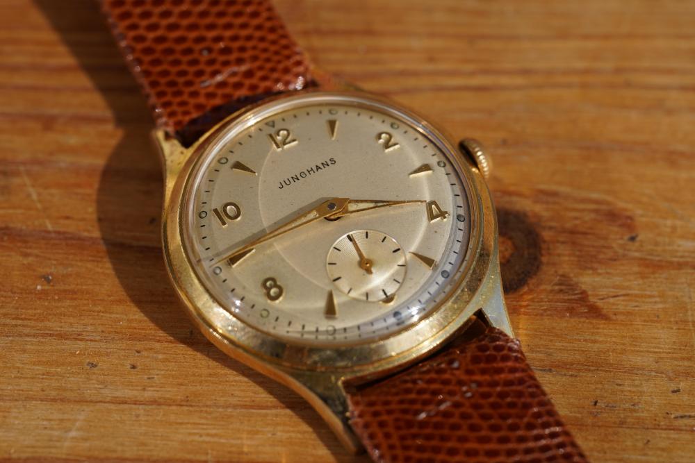
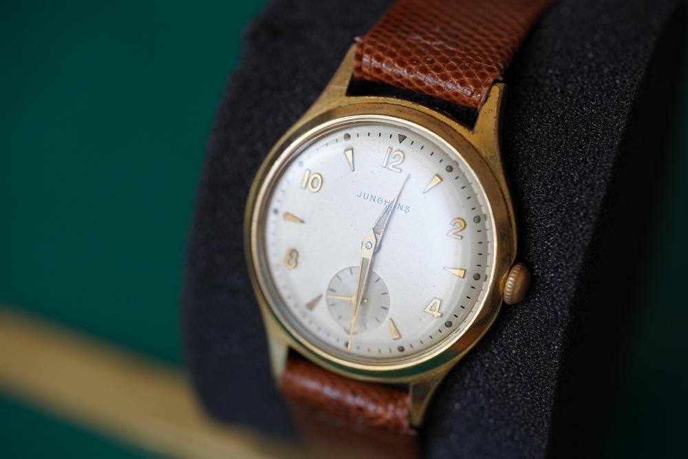
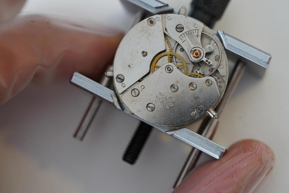
Hi everyone! This time I'm back again with a little something which turned out to be something of a hybrid project. I had repaired and planned a video on a Junghans watch with the 93 movement caliber to give to my younger brother ( which young adult doesn't need a nice looking watch) and had it all set out, planned and executed. The only downside was that the dial was slightly discolored on the right side due to bad cleaning on my part. Here you can see what I mean by that: But I happened to be at a local fleamarket on the day when I wanted to finalize the video and surprisingly found the exact same model! Even though the crystal was pretty scratched up, I was confident that the dial was in a good condition so I bought it for 10 Euros. And yeah, it looks like I hit the jackpot: So.. I got lucky and changed the dials in the end. But enough rambling around and here is the actual process of working on the watch movement: 1. Removing the movement from the case. This movement was from the “trilastic” model line of junghans and it got its name from the tri-legged support beams which held the movement inside the case. Just pop those up and remove the movement. Fun fact: While checking the inside of the caseback for marking I found one from 1981, thats so coooool! : 2. Remove the hands and and then the dial by unscrewing the dial feet clamps ( Forgot to take Pictures sorryyy) 3. Strap the movement into the holder and unwind the watch if needed. Then I removed the broken watch stem. 4. Remove the blued ratchet and the click spring 5. Remove the hour wheel, minute wheel, canon pinion and the very interesting looking yoke and its spring. 6. Then remove the clutch and flip the movement. The leftover lever will be released from the backside later on. 7. Remove the balance wheel and the pallet fork system. 8. Then remove the two screws holding down the mainplate and lift that. You can go ahead and unscrew the screw in between as well since that will release the left over lever on the front side. Do the same for the mainspring cover. 9. Remove the gear train and the mainspring And that's about it with the disassembly! Now moving on to the whole cleaning, lubrication and servicing part! Mainspring service: This Mainspring was something new to me since it had a very interesting arbor! Instead of the traditional small arbor inside the barrel, it extended outwards and acted as a lid and a wheel at the same time. While this is definitely cool, it also brings some negatives such as faster exposure to dirt and etc with it im sure. It looked fine so I just recleaned, lubricated and reinserted the whole thing: Lubrication: Here is a list of lubrications I used Moebius 9010 - All jewels Moebius 8200 - Mainspring and barrel lubrication Moebius HP 1300 slower moving parts such as canon pinion Moebius 9415 - Pallet Fork hooking jewels Molykote DX - Gearless works and high contact/friction zones (Front side only really) Oh and of course don't forget to clean and lubricate the balance shock jewels! Reassembly: Just reverse the disassembly steps or watch (no pun intended) the video for a step by step walkthrough. Timegrapher Test: Before Regulation After Regulation: Now i'm very happy that the rate is so much better. The amplitude can definitely be better however I would blame the old mainspring for that. The one thing that puzzles me really is the Bear Error. I've tried virtually every combination on the balance but the beat error does not improve. Maybe something is wrong with the hairspring? Final Result: After attaching the more aesthetic dial and recasing the watch and adding the straps, these are the final result pics: I must say I'm very happy with the whole process! Of course there were some up and down moments like when I destroyed the balance ( don't even ask) and had to get a replacement and such things but it all worked out in the end did it not? I was not sure how the beat error and the lower amplitude were going to show themselves while wearing the watch so I did a test wear for a week and the time only deviated by a second or two so I'm relieved! Now I apologize for the lack of pictures for a smooth documentation, I forgot and yeah, the rest is history. However, I have uploaded another fully commentated video so If you want explanations, more information or just a smoother experience go check it out: https://youtu.be/ZDXKiNnrmMk Any criticism, questions, comments and tips are always welcome and i'm happy to talk to you all! Hope you enjoyed it and until next time! Stay Healthy!


 1 point
 -
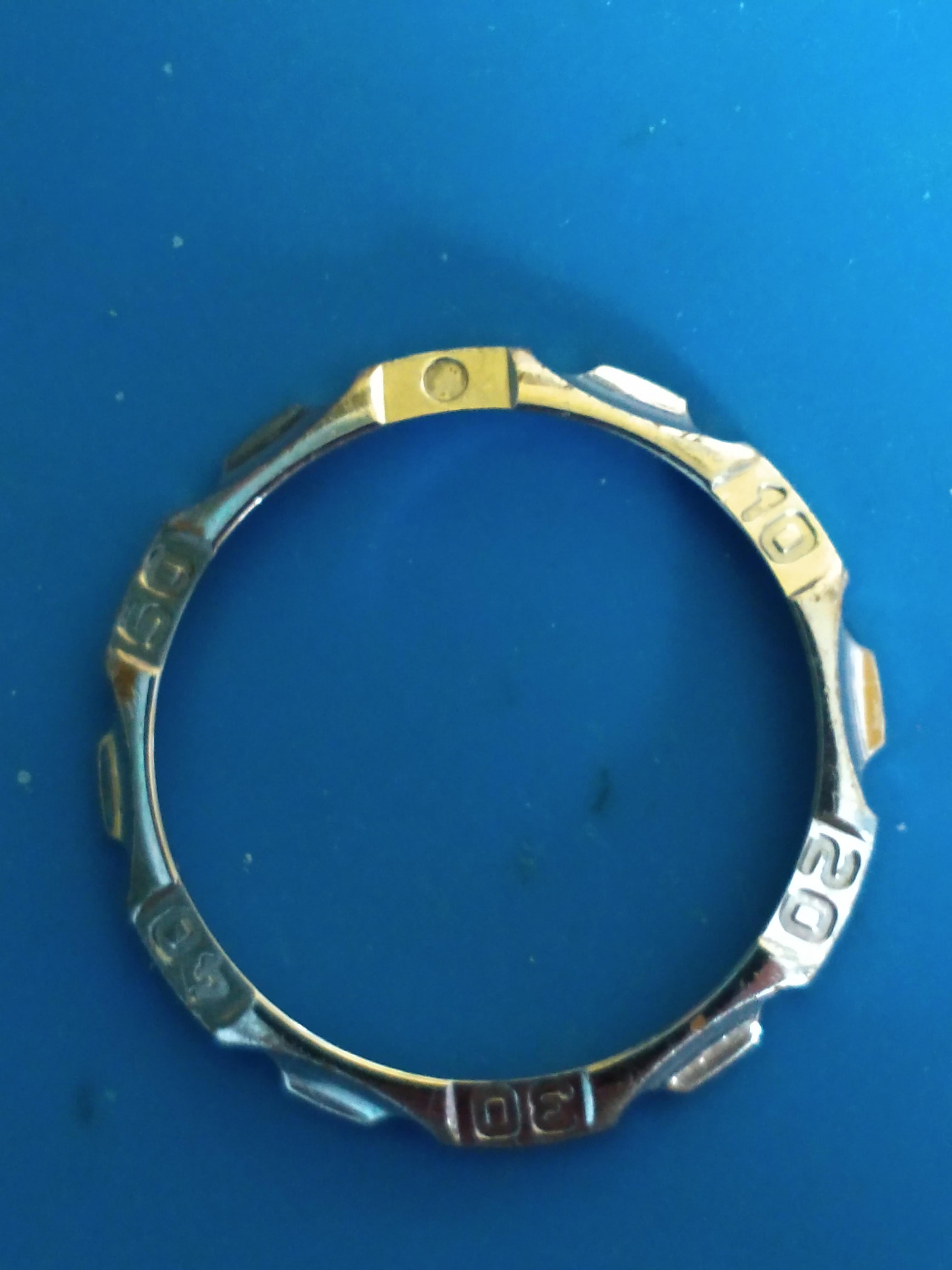
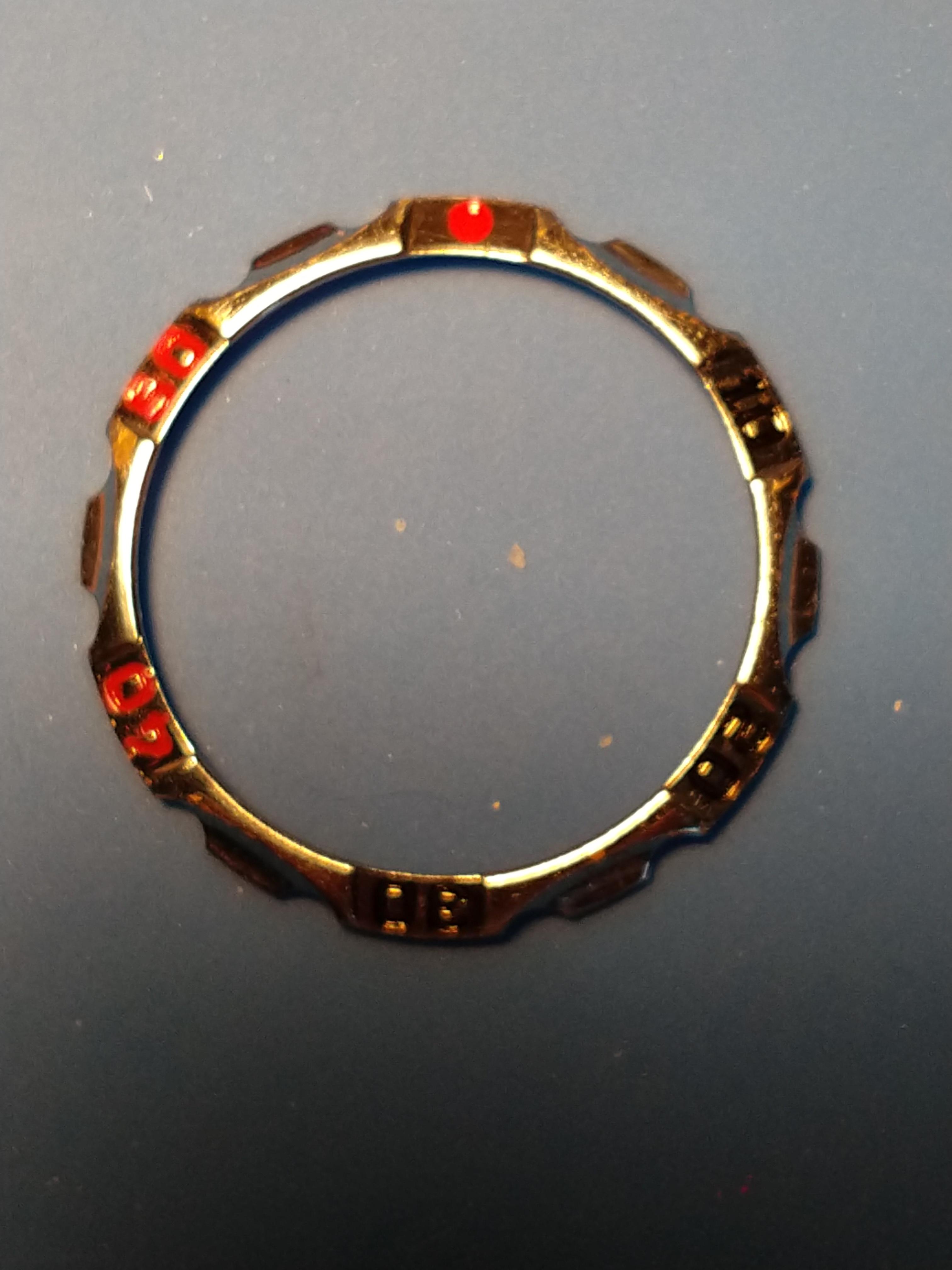
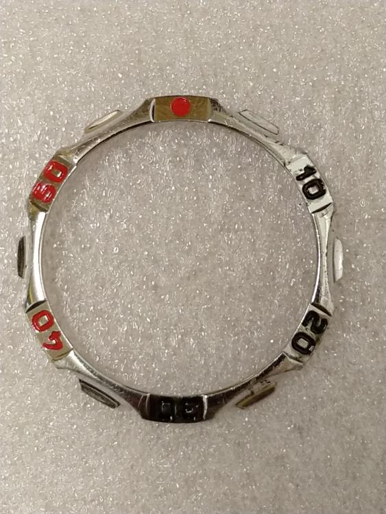
Hi there,Well here's the finished result of the bezel after baking.I found the video of this painting and baking of bezels it's on YouTube in a channel called Red Dead Restoration and the video is Abandoned Breitling watch.The person uses Porcelaine Paint Pencils which I have just received and they have a very thin needle/tube where the paint comes out much better than the liquid paint and less messy.Photo of the finished bezel enclosed.


 1 point