Leaderboard
.thumb.jpg.cb17a66989f1e796fd4217db2e9ca9df.jpg)


Popular Content
Showing content with the highest reputation on 02/12/25 in all areas
-
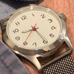
No comments. Just watch this...4 points
-
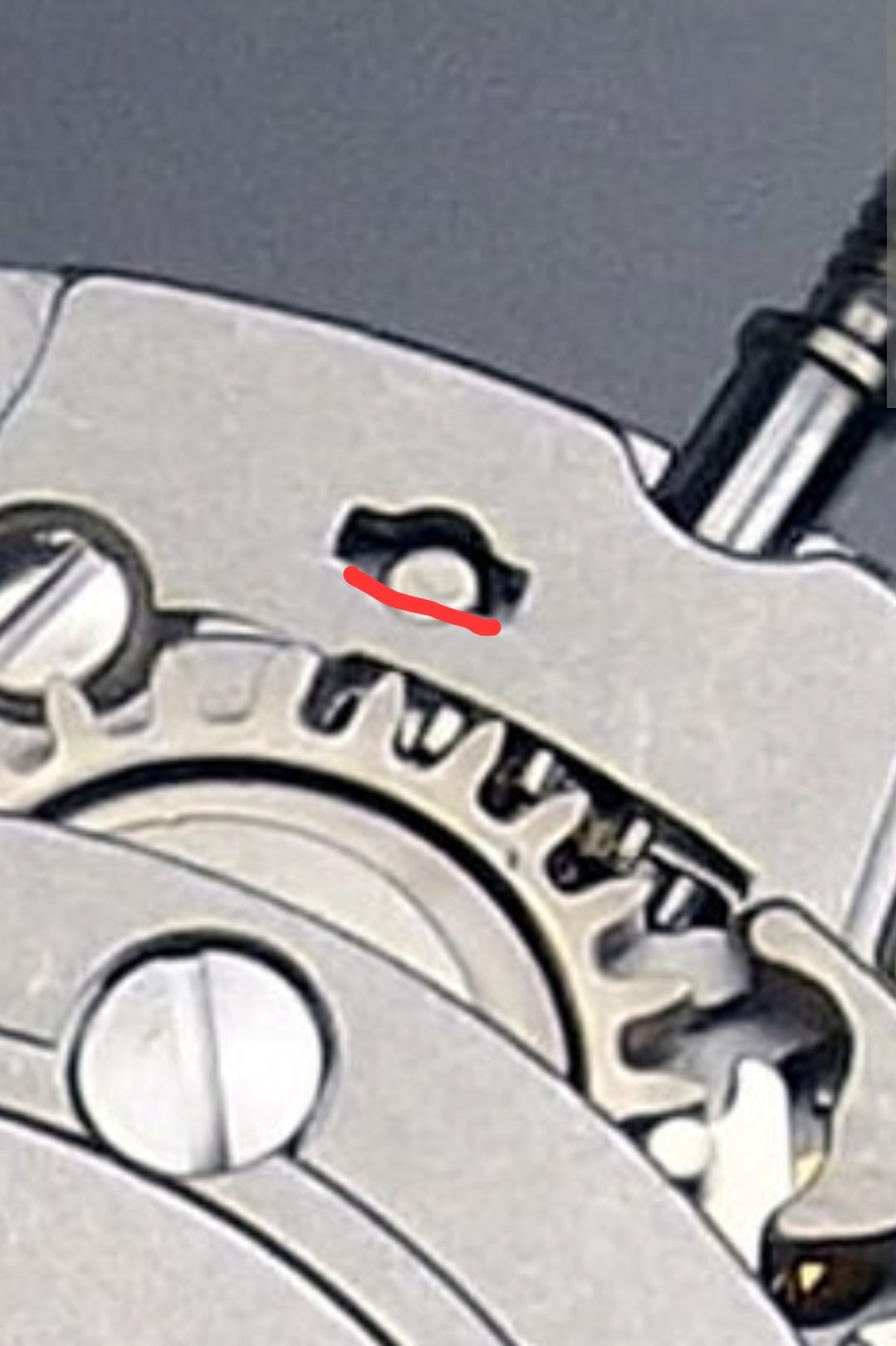
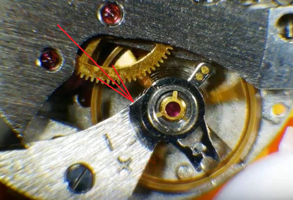
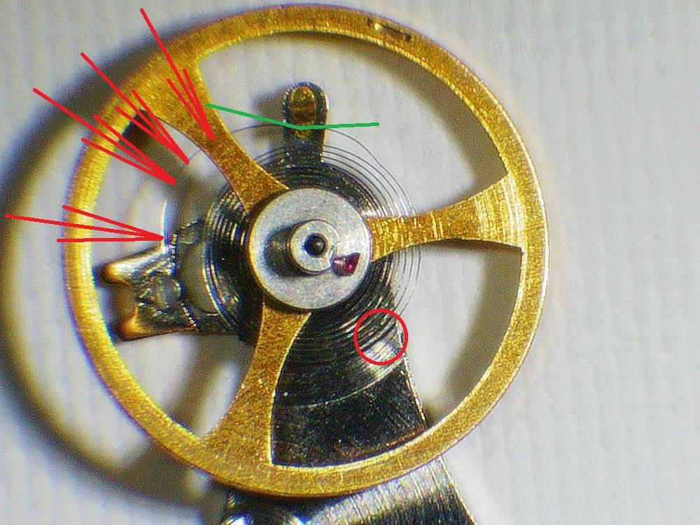
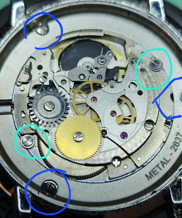
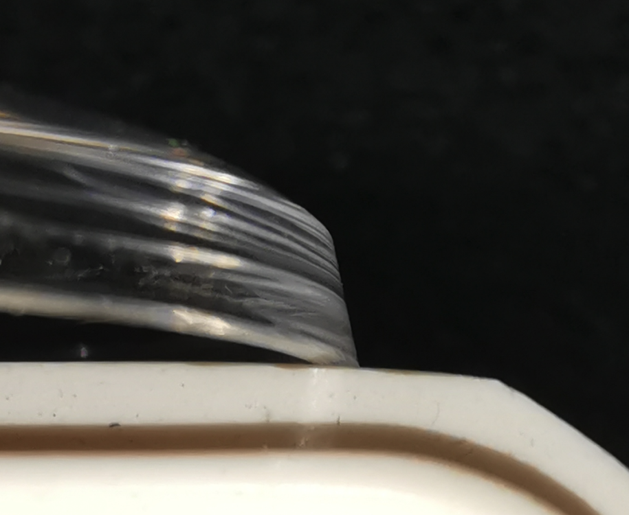
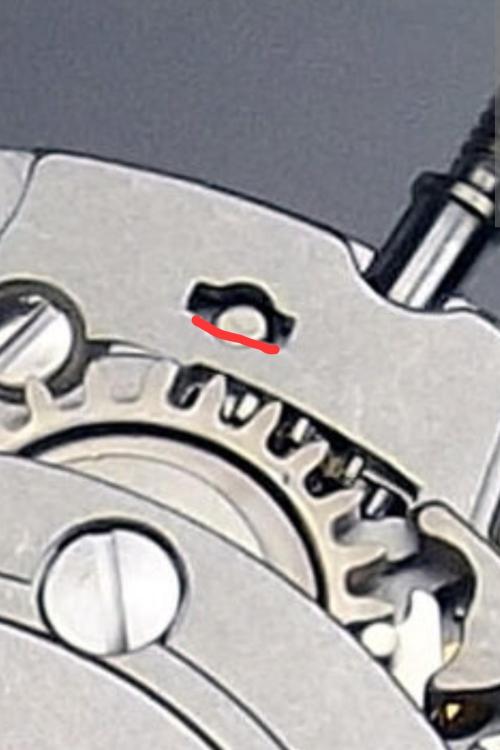
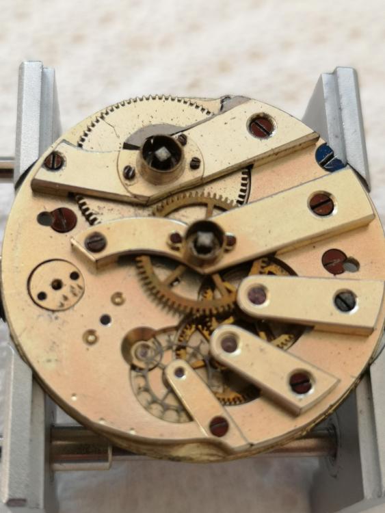
OP, You main problem is the hairspring. The free oscillations test shows not only losses, but higher frequency when amplitude is small. This, and the fact that the hairspring doesn't move where the arrow points when small amplitude, together mean that the spring is pressed to the cock. It is not only touching, but is firmly pressed. Then, next picture shows some problems that need to be addressed. You have one sharp local bend where the green lines show, it needs to be straightened first. You can shift the regulator as the place is just where the regulator is. Be careful as this bend has happened by the regulator shifting back while the spring has stuck between the pin and crud. When done, return the regulator back where it is on the picture. Next to do is press where the red arrow show. The end curve is now bent as it's radius is smaller, the bend is on entire length and not only on single place. Pressing where arrows show while the spring is rested on the regulator will bring it back to normal. Finally, the red circle shows where the spring is pressed to the cock. It will need some twisting to do in order to rectify, but please, remove all the bridges and parts from the main plate and put only the balance with it's cock, then make some side view photos to see where the spring needs to be addressed. Normally I would advice to remove the balance from the cock for such hairspring repair, but here the stud carrier is a 'pinch' design and placing the stud back is specific. Not that it is hard to do, but I will have to write a lot in order to explain how.
 4 points
 -
Our next party question. What are two separate parts that are inseparable?3 points
-
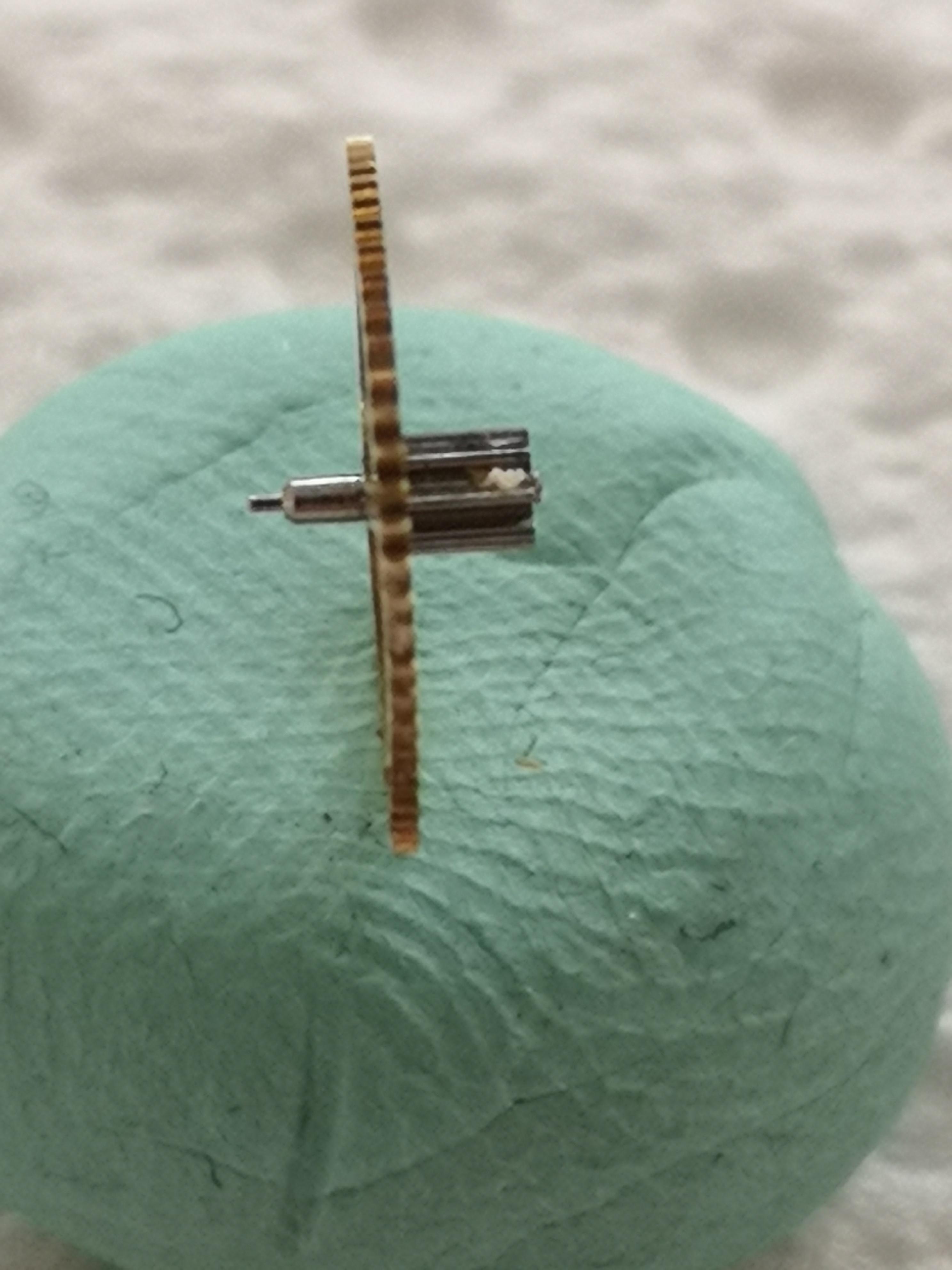
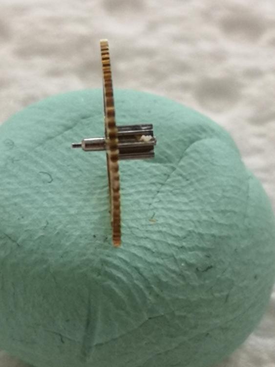
Oooookkkk everyone! Thanks again for your help. I can now confirm that it was the balance wheel / hairspring mix-and-match. I know, most of you were sure already, but I was still a bit incredulous about the MASSIVE deviation (close to one HOUR per day). But yes, that was it. I put in a balance from another 2414 and it worked very well. I put the two hairsprings next to each other (the one matching the balance wheel and the one I used) and I "feel" as if I can literally see the difference in thickness. I took a photo, but somehow it didn't save Anyway, I'll now be trying to bend the old+correct hairspring into shape and put it on my freshly restaffed balance wheel3 points
-
Great thread. As part of my lot buy, I got a bunch of wheel cutters. I checked and one appears to have the correct profile. I have a servo driven rotary table on my Sherline mill. I can dial up the necessary rotation angle. As luck would have it, I found a ratchet wheel in a bottle of ratchet wheels!! Imagine that!! I may still attempt a repair.3 points
-
The best and most concise description ever written of how it should be done! This is what it should look like.
 3 points
 -
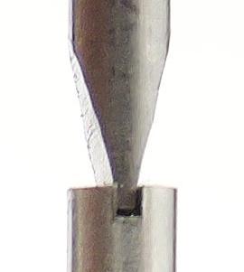
Use the widest screwdriver which doesn't overhang the ends of the screw slot. Stone the width of the taper so that it wedges deep into the slot without touching the bottom. Hold the screwdriver vertically, push down very firmly, and twist anticlockwise. If you do the above, the tip will not slip.3 points
-
Let me bring in an other perspective: Could it be, that this guy has to make a living repairing cheap watches for poor people? It reminds me of botch jobs we’ve all seen before, many of them done in the 1970s by desperate watchmakers whose customers told them to get the „wortless“ mechanical watch running for just a few bucks. It had to be done quick and dirty.2 points
-
print out the drawing to size, glue it to some spring steel, and get busy with a jewelers saw and escapement files! Surer it'll take some time, but its faster than waiting for something in the mail.2 points
-
Fleurier/FEF 105B https://ranfft.org/caliber/4681-FEF-1052 points
-
Well, lesson learnt! You know what they say about assumption. Turns out I had put a wrong screw in the dial side that was fouling the barrel. Only slightly, and fitting the pinion must have moved something a little, who knows. But it's back up and running now. I guess if i can't work out why something is a problem, maybe it's NOT the problem!2 points
-
That's just stupid, isn't it? I mean, it's completely useless then, no? If you have to reshape them to use once and then they deform upon first use.... and if the steel is softer than the balance staff, will it even rivet at all? As @praezis wrote, what are all the other buyers doing with it?! It triggers another thought: how amazing were tool 50-100 years ago!! With much less technology, they produced such precise and robust tools that we still use them today. I just checked my round punches of my old Boley set and there's not the slightest trace from my first balance staff riveting.2 points
-
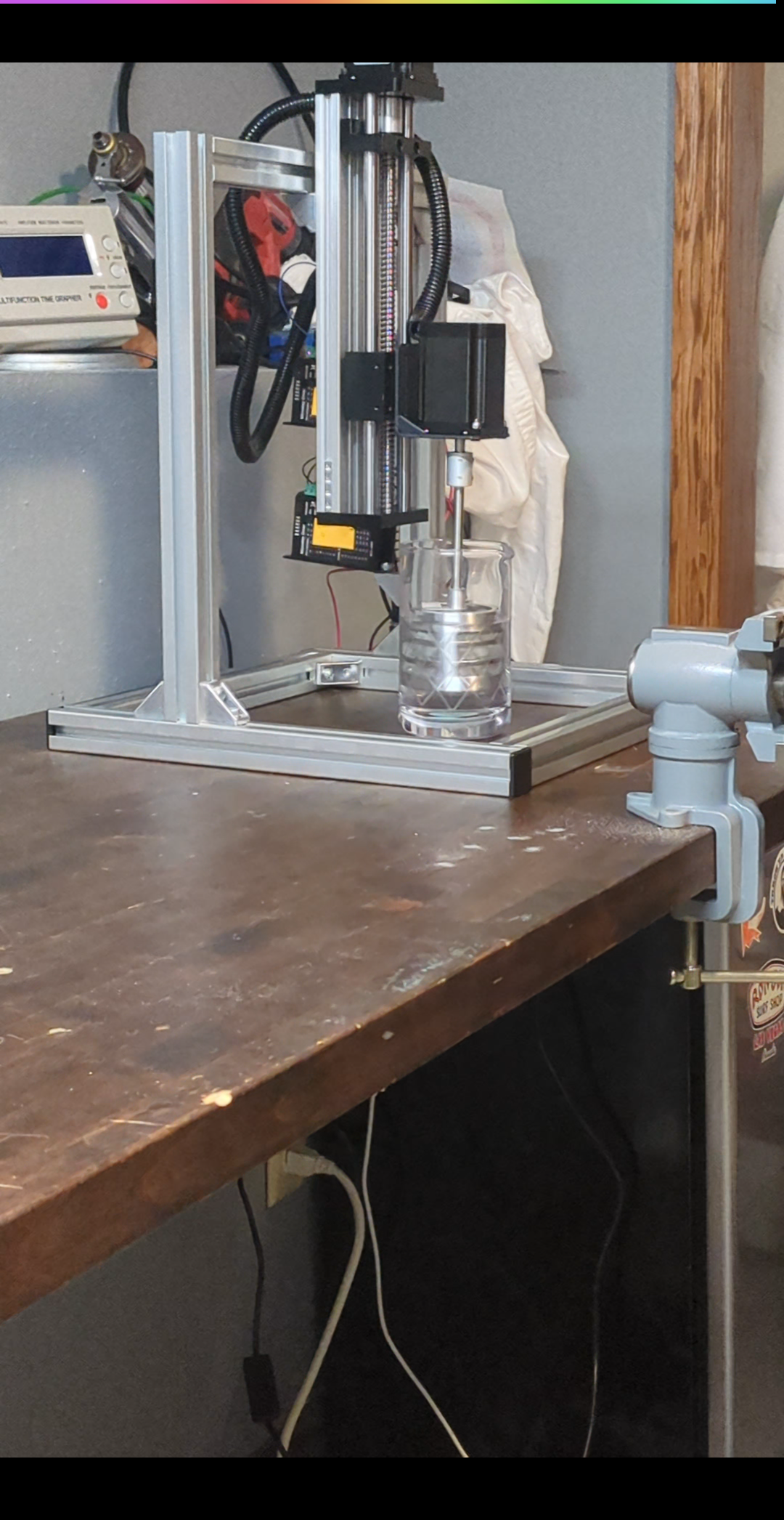
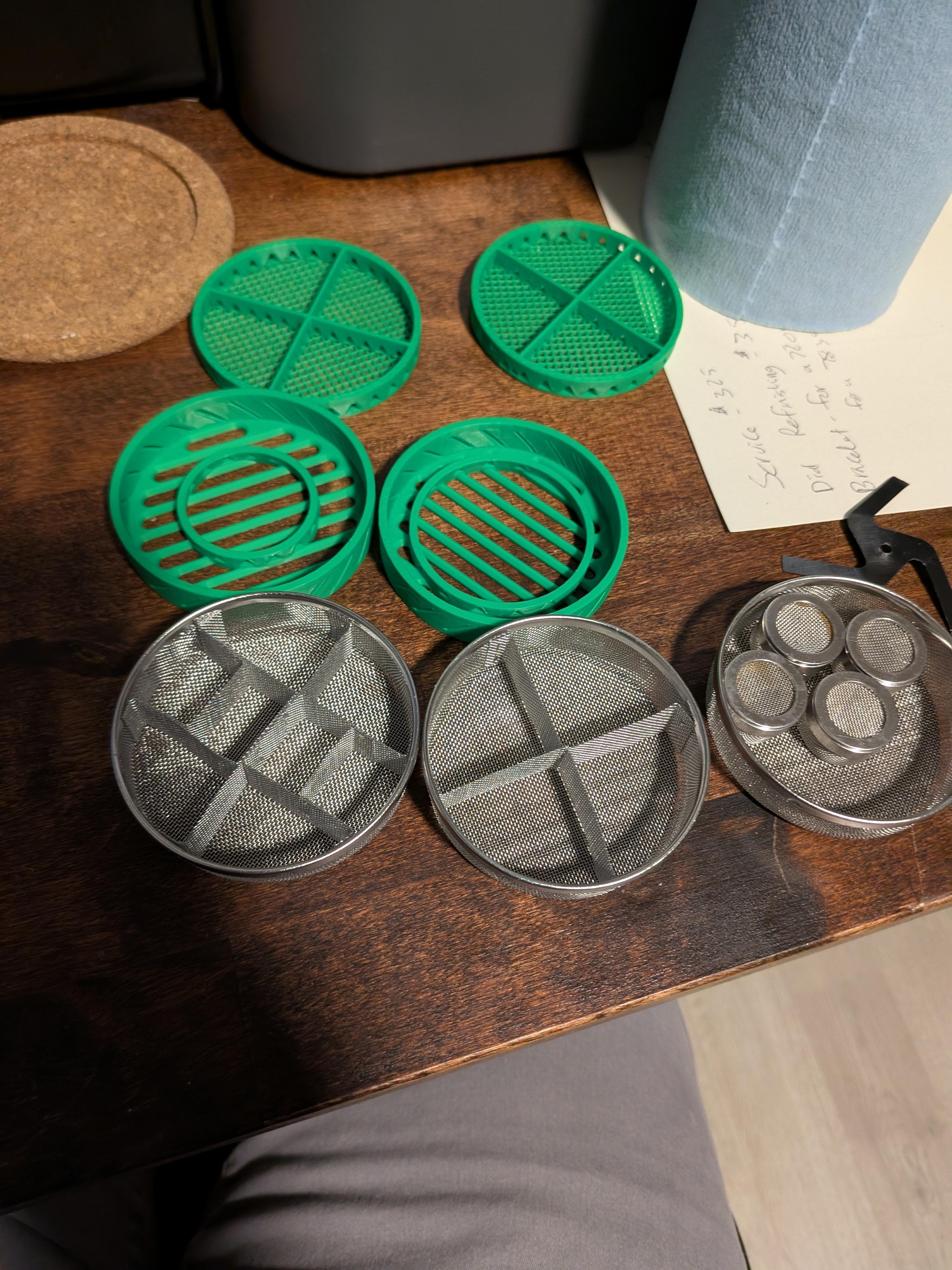
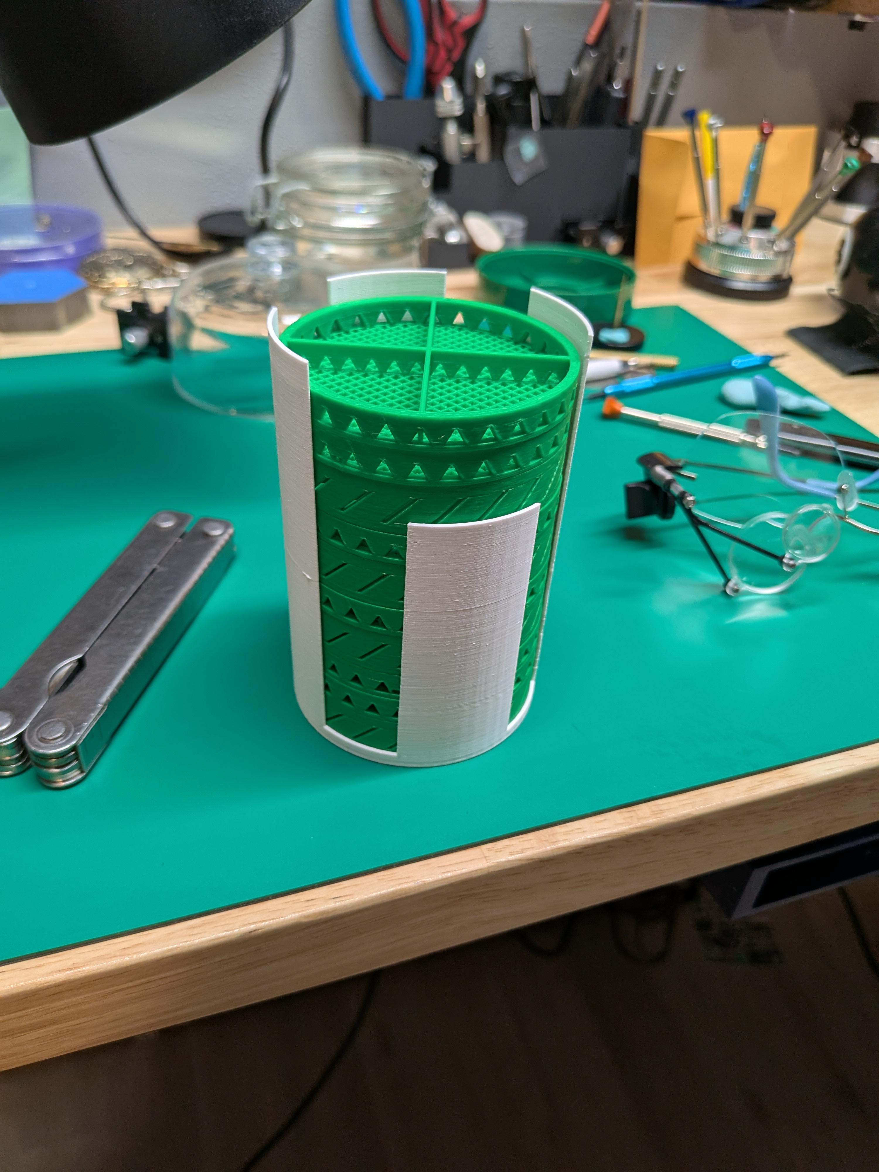
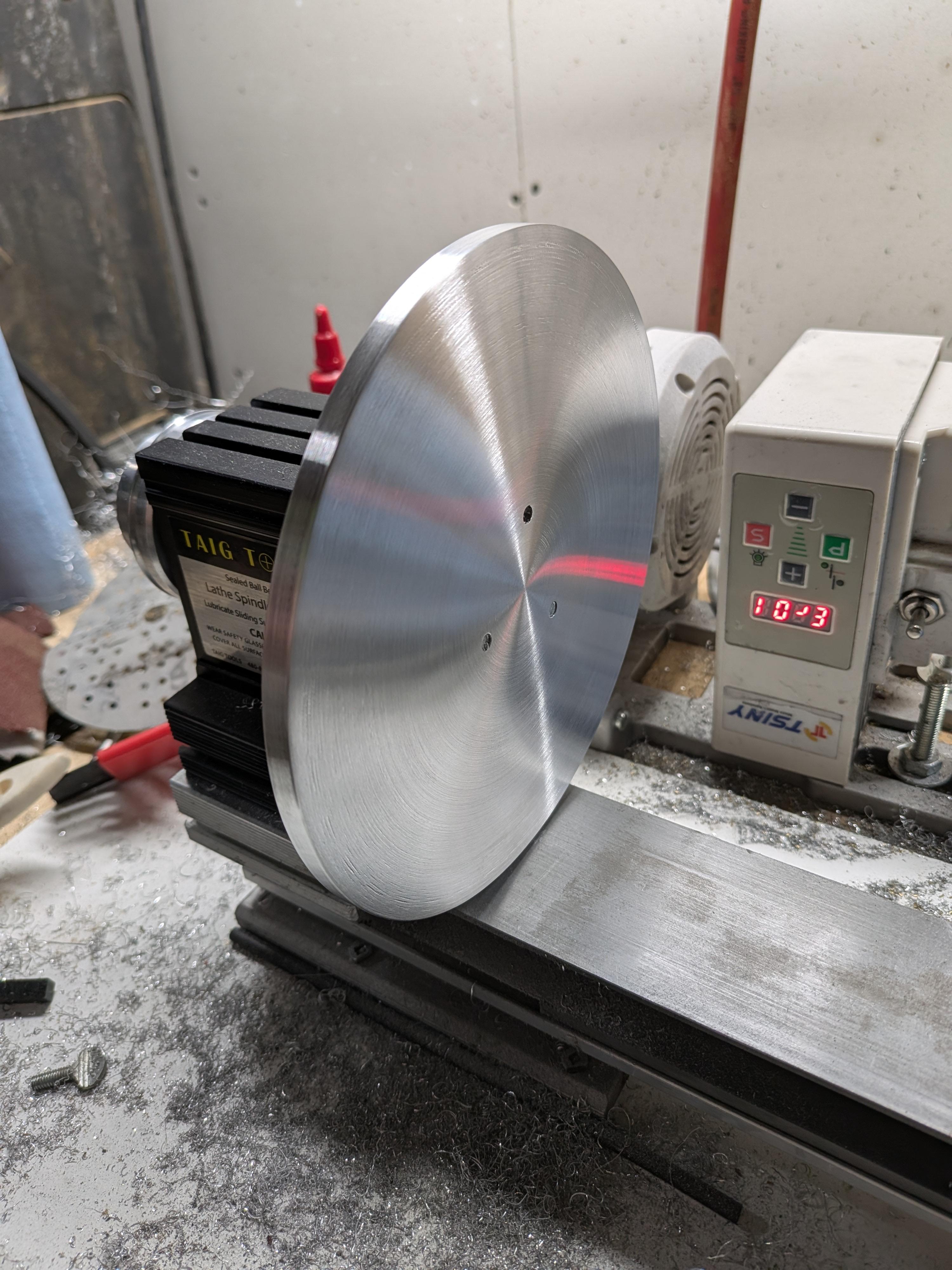
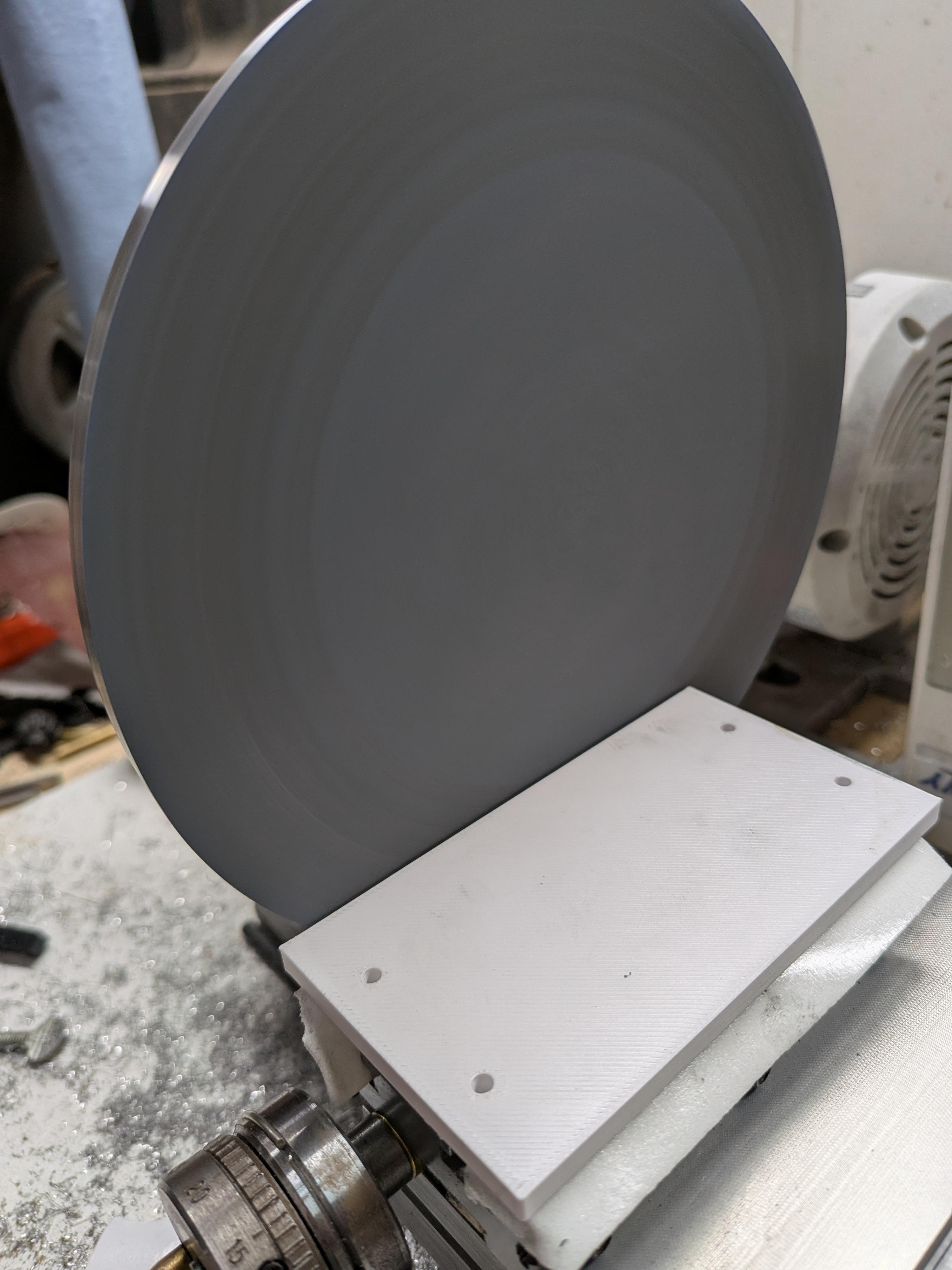
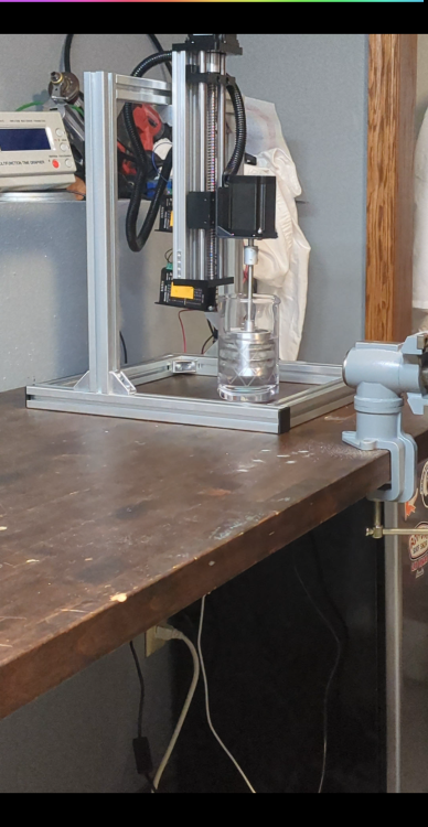
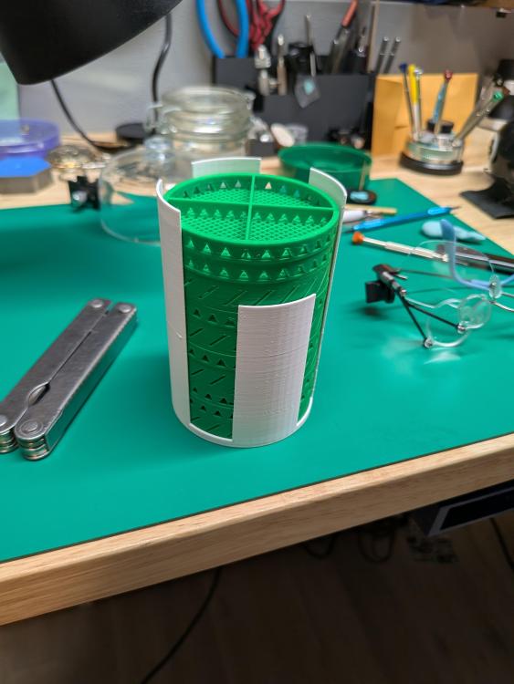
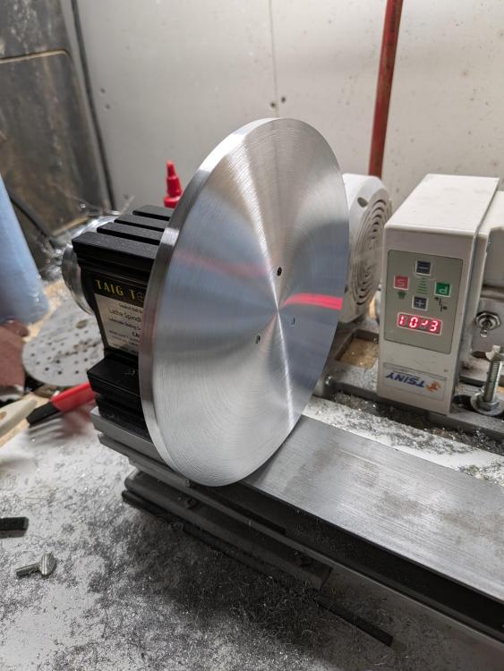
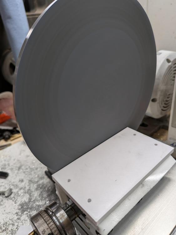
I figured I should actually post my tool builds here. I like making tools almost as much as I like watchmaking. I'll post new tools I make below and label them. First up, my cleaning machine. You can see my other post on it. Next up. Some parts I make for the cleaning machine. Baskets and such. Then I made a toolpost grinder setup for my flex tool. This will be used for precision grinding, and also for wheel and pinion cutting. Then we have the lapping table for the lathe. The is a simple build. Next is a 2 axis polishing vise. I'll add more later on

 1 point
 -
My problem with Sellitas is the keyless works. Ive seen multiple issues with them, mostly stemming from the stud on the setting lever that sits in the stem being too short, and allowing the stem to be pulled from the watch unintentionally. The stud is visibly shorter than its ETA counterpart. I also don't like the setting lever spring being attached to the set bridge jumper. That's not a Sellita problem, just a complaint on the ETA design. But, being able to buy the parts also makes it a nice movement to service.1 point
-
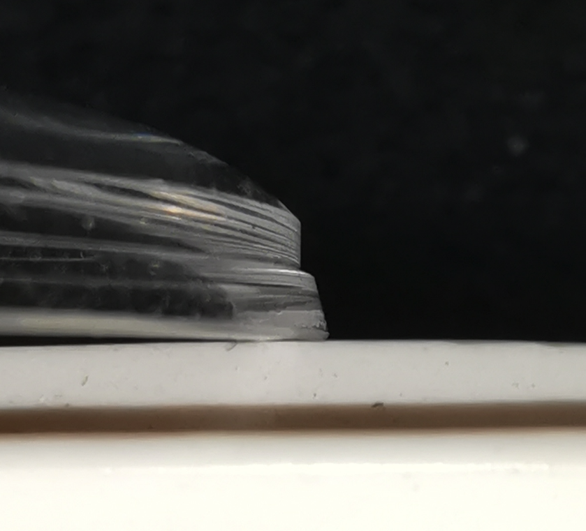
How accurately can you measure how much of the movement stands above the case rim and compare that to the recess in the caseback.1 point
-
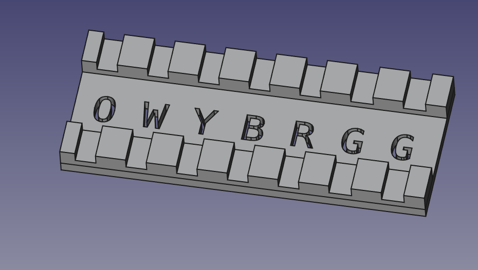
I had never heard of gridfinity before, it looks really interesting. I'm going to try it with the drawers in my Bisley cabinet.1 point
-
There is no 105B and Bestfit is just showing 2 possible options for the keyless works. The photo from Ranfft is the 70 which has exactly the same keyless works as all the movements listed do.1 point
-
Not that easy to photo as you can see above and always good to have a reference to work to for future projects.1 point
-
Thanks ever so much, Mike!1 point
-
Yep. I have worked on maybe 7 or 8 HMT's and I am always annoyed when each one that comes in is 5-8ms out of beat without a movable stud carrier. But seeing this I'm now pretty impressed.1 point
-
I just dropped off with the owner, and he was pleased. Job done.1 point
-
Now that seems like an interesting thing to ask AI. ChatGPT's reply. Now obviously ChatGPT has made some fairly broad assumptions here, and it does clearly make the point that most legally owned civilian guns are not used for violence against other citizens, but it does illustrate the problem of estimating the value versus risk of firearms. You could argue of course try to make the argument that any manufactured item has risk of causing death, auto-mobiles being perhaps the obvious one, and that we should not therefore worry about this. The risk is unavoidable. This kind of misses the point of course. We do have laws about cars and car use and ownership. We have laws about use of asbestos, sales of tobacco, use off recreational drugs and so forth, and very few people object to those. Gun ownership in the USA is a very strange animal in that sense. Because the "right to bear arms, and the right to arm bears" is enshrined in the US constitution, it seems to have attained near mythical status. We get the strange argument that the solution to school shootings is "more guns". "We should arm the school security" being one of the more illogical responses. As you can see, AI, while it can distil the facts to some degree, is no more capable of solving the firearms conundrum than the 8.2 billion humans are. Perhaps a better more targetted (pun intended) approach would be to ask the more direct question... This was met with he following response.. .. so perhaps this estimate of one violent death per every two to three hundred guns produced in the USA could be considered a "better" estimate, but it is still a pretty grim statistic. A further question ... Yields this response... .. So statistically speaking, on average, every gun shop in the US is responsible for one violent death per year. Of course this is a highly debatable result, but certainly food for thought.1 point
-
This thread has answers to what You ask, it is long but interesting. https://www.watchrepairtalk.com/topic/30710-my-2nd-attempt-at-making-a-balance-staff/page/2/1 point
-
But don‘t touch the dial with your caliper, as shown in the video (1:51)!1 point
-
Just to be clear, I'd expect a casing situation like in the image below: Two clamping-screws (i.e. screw with integrated clamp) and 2-3 casing clamps and screws. Or a plastic holding rings, as @eccentric59wrote. But I think @mehmgot this covered.
 1 point
 -
Yes, I had the same experience as Kalanag, with the tips of the punches deforming when riveting a balance staff. And the rounded punches need reshaping because they are not rounded all the way to the hole. So the part of the rounded punch that strikes the balance staff might as well be a flat punch.1 point
-
@eccentric59 @Knebo my problems i mean the doubt of mine is solved, i had a doubt about the movement in the movement ring, and i got your point as well eccentric but if i asked myself and everyone i do believe there should have cut off (point or space to fit the clamp in movement ring just like we have in case that hold the movement ring case , if thats not then i totally agree to the point that knebo shared that we dont need clamps again if the flat screw in fitting the movemnt ring very well, no shaking of movement and no wiggling in that case , but thank you coming up with great image @eccentric59 to make me understand well thank you again looking forward to coming up with new curios doubts, and discuss with you"ll1 point
-
HWS 30.4 has an internal height of 3mm and an overall of 4.4mm HW 30.4 has an internal height of 2.8mm and an overall of 4.3mm There's also the HH which has a similar profile to the HW, I've not got one but the catalogue shows an internal height of 3.7mm

 1 point
 -
Not used my set that much, but didn't notice any damage, although to be honest I probably didn't look. Will check them for hardness tomorrow and report back.1 point
-
I would love for small scale metal fabrication to reach the level of ease of 3D printing. I just had to pay $20 to get a setting lever shipped from the Netherlands on Ebay, I could remodel that part in Fusion 360 in an hour but have no way to actually make the thing.1 point
-
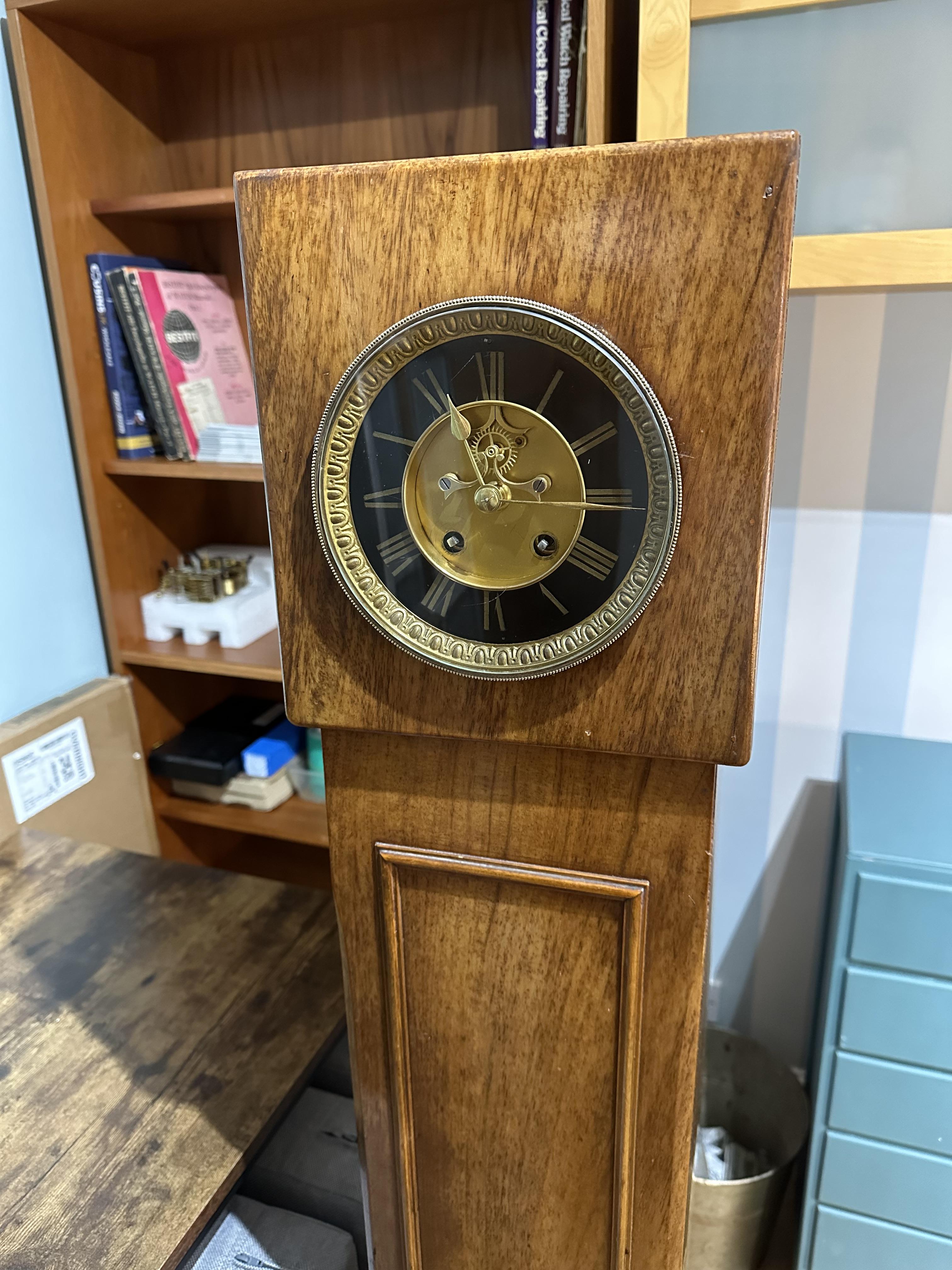
Certainly not GUSTAV BECKER. 4 8 The effective pendulum length is 4 pouces and 8 lignes; a pouce is an old French inch, and is 27.07 mm or 1.066", and a ligne is a twelfth of that, 2.256 mm or 0.88". So your pendulum should be approx. 126 mm long1 point
-
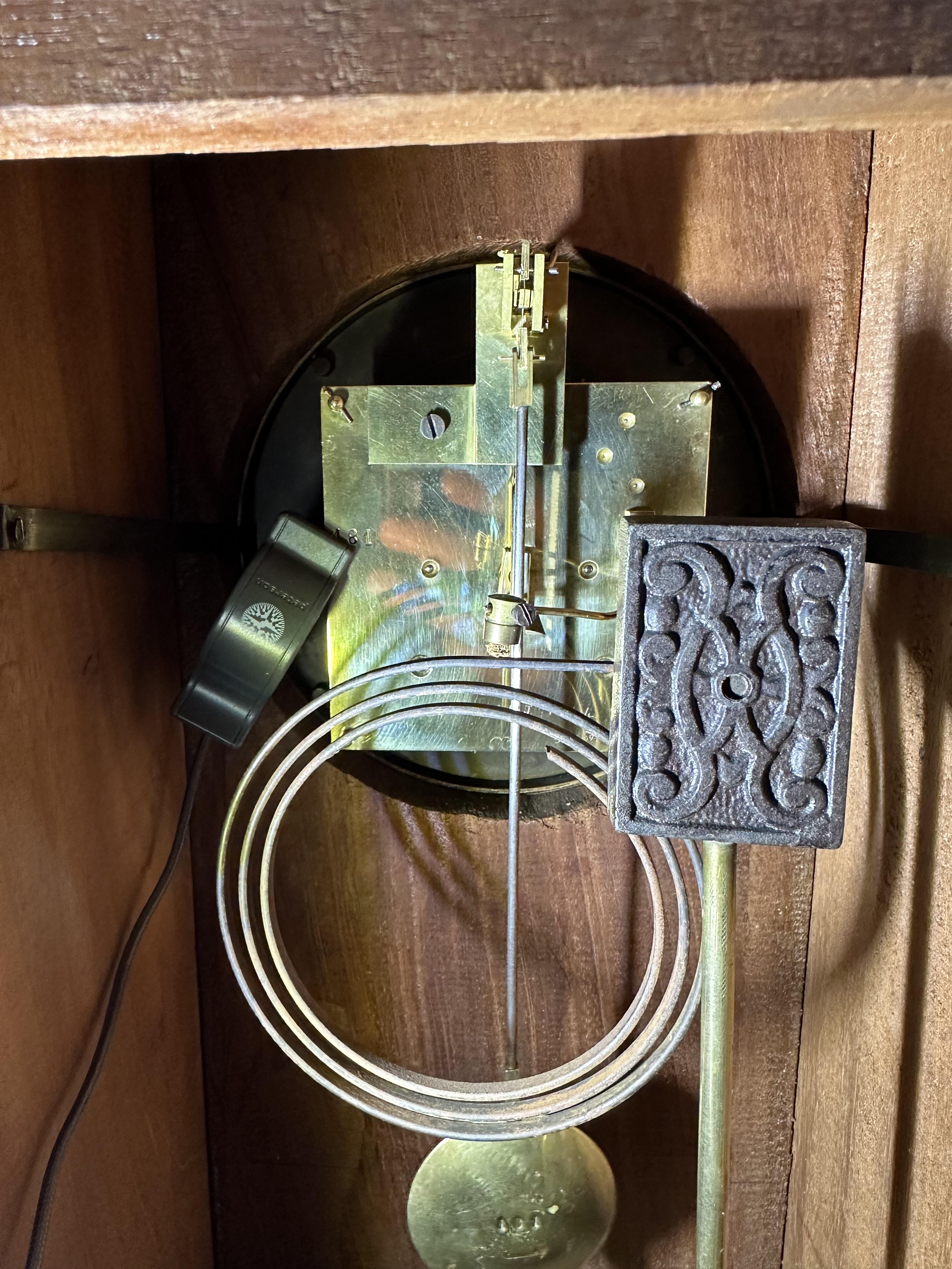
Hi. Is there a makers mark/logo on the back plate. I am at this time repairing two french clocks one by AD MOUGIN and SAMUEL MARTI, both have pendulums of different lengths and weight. If yours has no marks it could be one of several makers such as HAC and others who produced clocks in the French style. Donald De Carles book “ Practical Clock Repairing has a chapter dedicated to pendulum lengths and weights and calculations to determine weight and length Clock Repairing. By Laurie Penman also has plenty of advise on the subject. There is what looks like a mark to the left of thr pendulum leader, could be an anchor, if so GUSTAV BECKER1 point
-
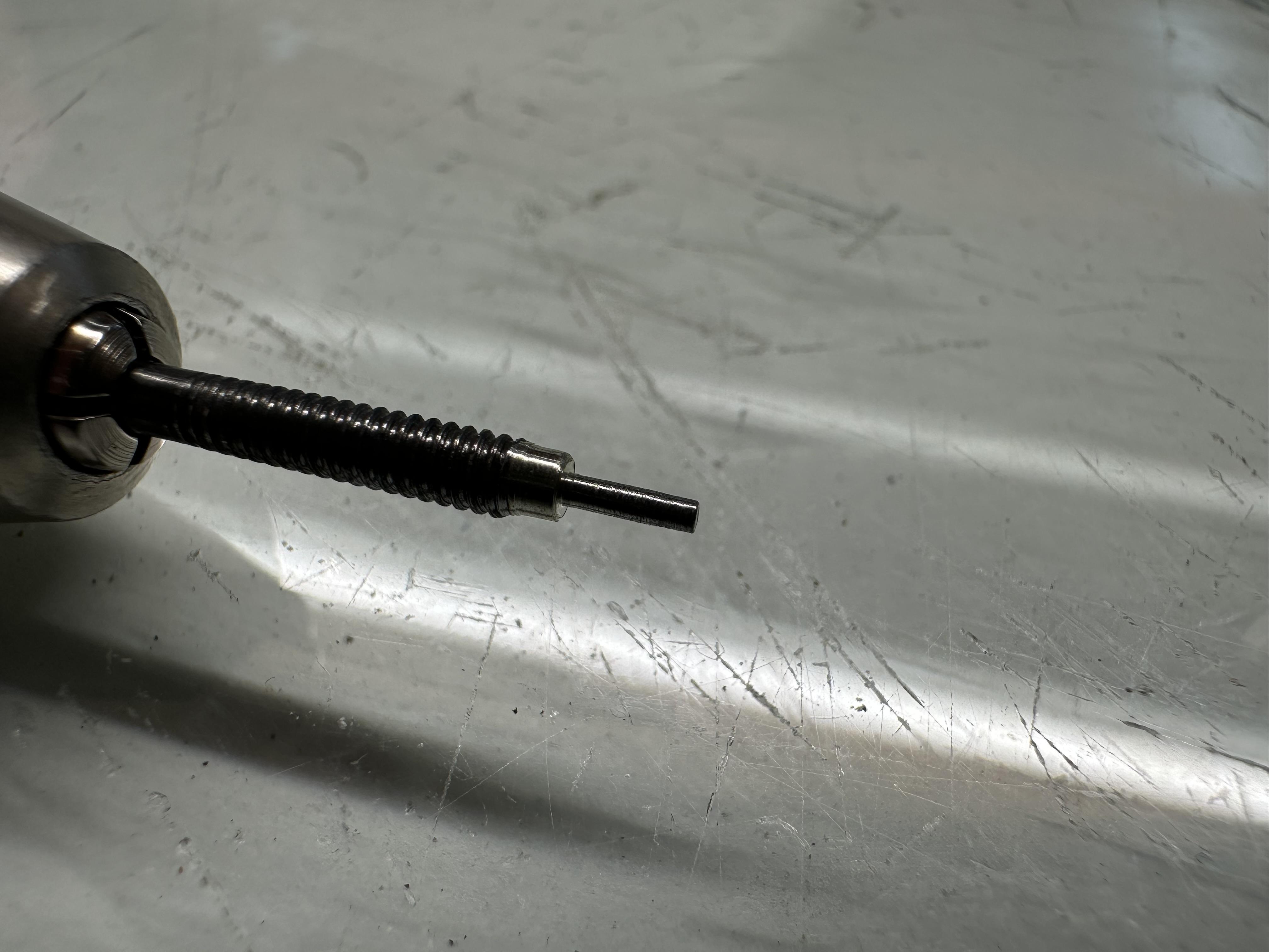
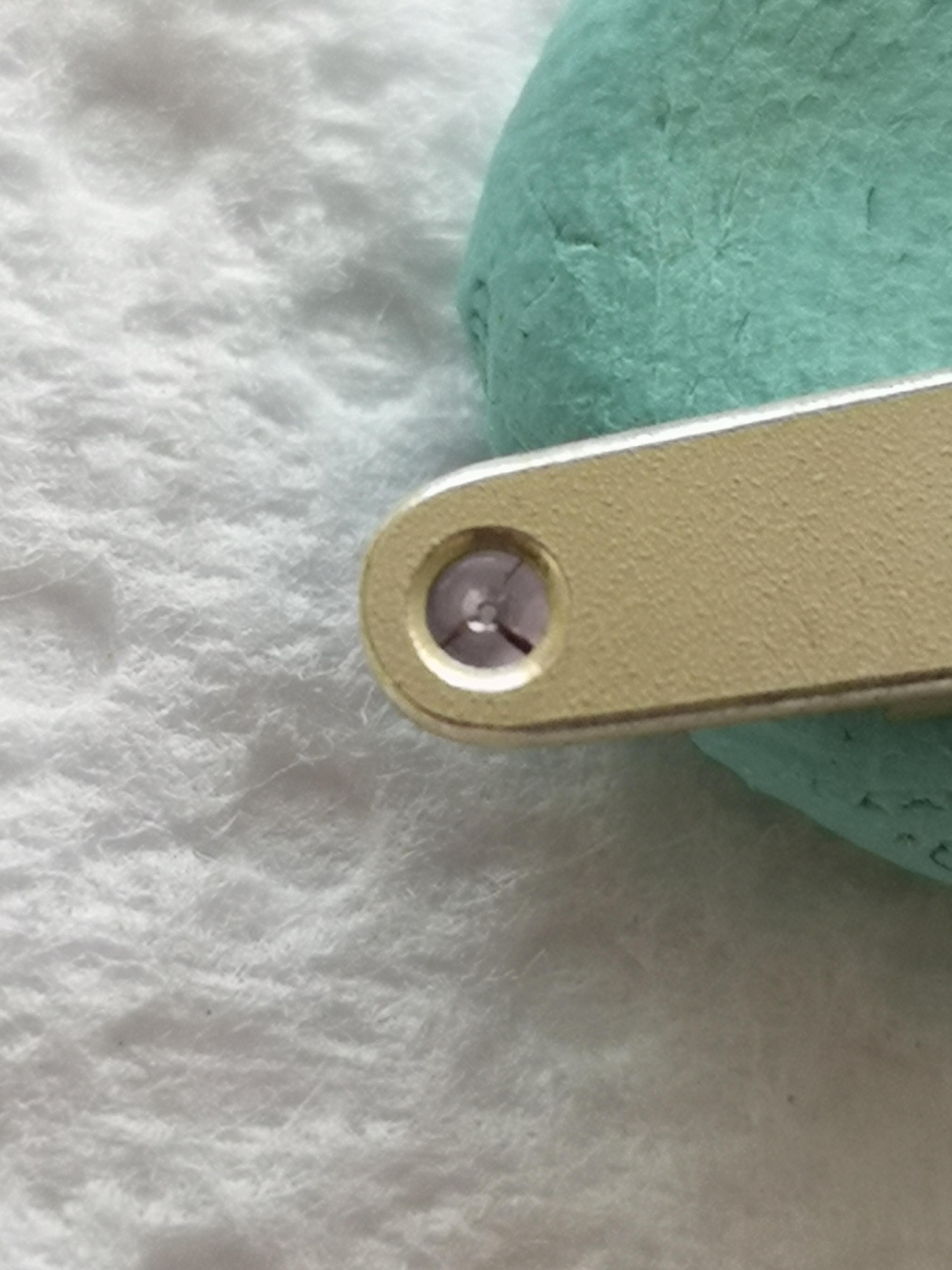
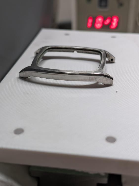
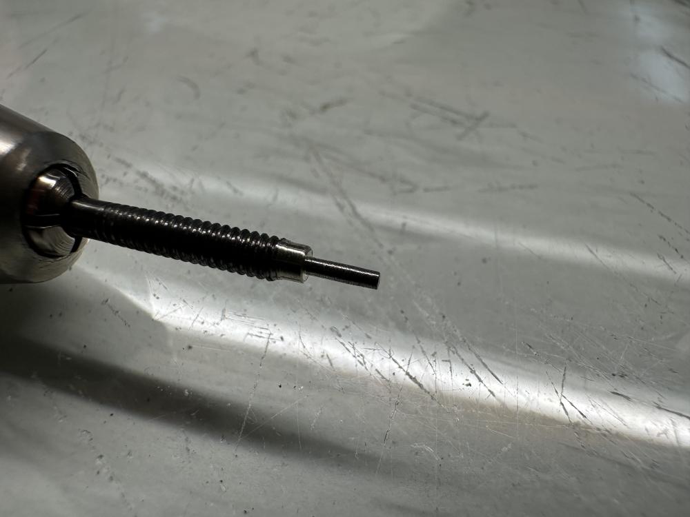
I managed to sort this in the end. A gentle couple of turns with a broach straightened things out. That allowed me to move on to the next problem, a broken pivot on the escapement arbour. I've never needed to replace a pivot before, and this is the kind of clock you don't just buy spares for.... The new pivot here is shown before polishing. I cleaned up the end of the arbour, drilled a new pivot hole, and silver-soldered a piece of blue-steel steel into place. Cleaned up the solder and pivot on the lathe, polished it up and fitted it to the clock. Quite pleased with the result, which looks more substantial than the original. The clock has been running perfectly on test for the past couple of days. Just doing the final regulation after casing it up, and it's back to the owner.

 1 point
 -
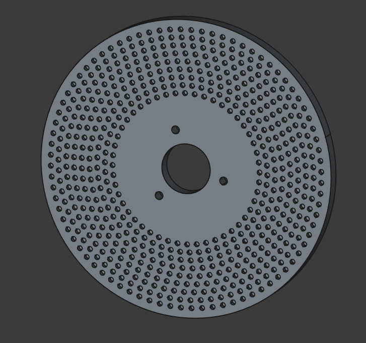
Wow my formatting was no good on the last post. Anyways, here is the latest build. A dividing plate for my lathe. I will print this part shortly, but I need to verify some measurements on my lathe before I do. My CAD software did not love me when I was doing this. Its a fairly easy part to design, just using polar patterns. So far I have settled on the following indexes: 80, 78, 75, 70, 65, 60, 56, 54, & 48. Trying to capture the largest amount of divisions I could. But I can always print another one.
 1 point
 -
Unless putting screws/ clamp back on, cause a problem, eliminating them isn't a good idea. Tightening the screws can force tension into the assembly thus affect amplitude or stop the movement, such that lossening the screws lets the movement start running again, even then one can shellac loosened screws fixed in place, so to prevent wear due to loose movement inside the case. I expect to get a frown from master praezis for this advice, but good portion of us are happy with the watch running and keeping good time. Rgds1 point
-
As here the conversation is about matching hairsprings/balances in russian watches, I have some information that will help to understand what is happening. The supplier of material for hairsprings is only one for USSR/Russia watch factories and they are not able to reproduce it with small enough tolerances. The batches of coils with the profiled wire (may be it is called ribbon or tape?) every time have slightly different thickness and other parameters. The hairsprings always are produced from the wire with same shape - length, diameter, number of coils and angle between beginning/end. Thus, when the wire parameters change with the next batch, the 'strength' of the new hairsprings changes too. To solve this problem, the balance wheels are turned with different moment of inertia to meat the different hairsprings strength for every new batch. Further, within every batch, the hairspring manufactured are tested and separated to 20 groups of strength, the balances again separated in 20 groups of moment of inertia and every group of hairsprings is matched to related group of balances. As the balance wheels are easier to manufacture with desired and predictable parameters, and the hairsprings is harder to make with desired strength, they first make the hairsprings with whatever strength will be and then make balance wheels to match the hairsprings.1 point
-
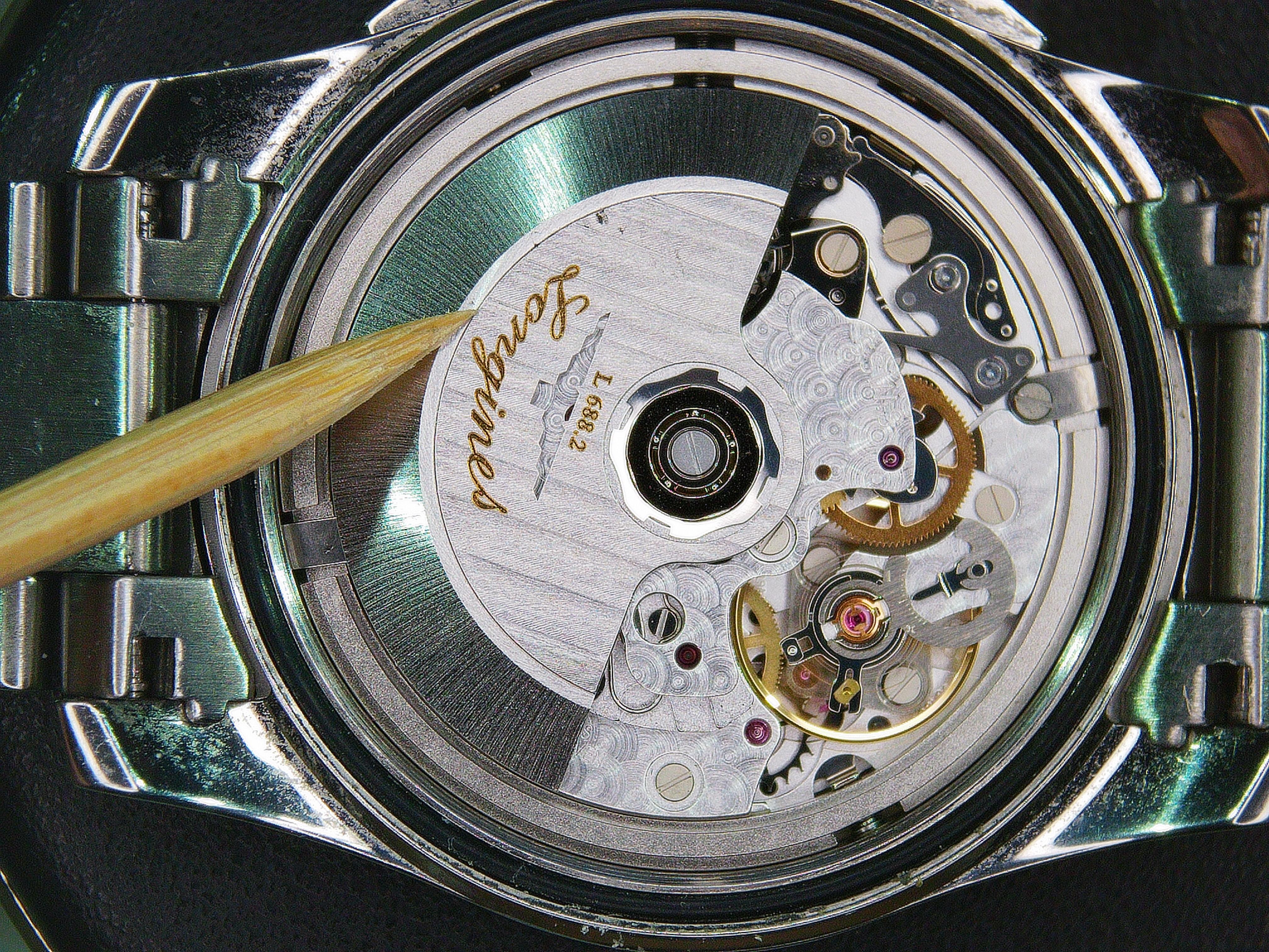
Not so fast. While @Knebo is most likely correct, I would point out that this only secures the movement to the movement ring. There are a few more considerations. How is the ring secured to the case? Sometimes there are case clamps that secure the ring to the case so that these shouldered screws are enough to hold the movement to the ring. Sometimes there is a plastic case ring that holds the ring to the case when the case back is tightened down. Sometimes there is a long case clamp that goes across the ring to the case itself. Like this Longines ... If there is no plastic retaining ring or case clamps for the movement ring, then the stem is the only thing holding the movement and dial in the proper position. If you assemble the watch without the case clamps and you pull out the stem and can make the movement and dial move by wiggling the crown, then I'd say the clamps would be a good idea, although it's odd to see shouldered screws used with case clamps. It's usually one or the other. The other thing to consider, especially with a 2824 or SW200 is the height of the screw head and clamp thickness. If the clamp is too thick and the head is too tall, it could easily interfere with the rotor.
 1 point
 -
The balance looks like it's very close to the back. Is these a gasket on the back?1 point
-
If you have access to a 3d printer have a look at the gridfinity system for drawer organisation. Tom1 point
-
No Andy, there is a diy movement for EDM cutting and boring. I can imagine where someone has the, I think best fit book where the keyless works parts are life size being able to digitise those and cut from the appropriate thickness spring steel. Another place it would potentially be useful is shaping HSS cutters for the lathe at small scales. I am not sure the cutter wire will be small enough to make watch wheels and pinions for a while but clocks it should be there now. i also should have added a fibre laser in the 50 watt range to my dream list for various things but definitely making dials and also cliches for pad printing. a man’s gotta dream, especially where tools/toys are concerned. Tom1 point
-
1 point
-
From a personal perspective I am retired like many here, to be fair though I started off in electronics and moved into IT where I spent most of my working life. I think that a lot of us are intrigued by how things work which is what tends to bring us into watchmaking. That curiosity often leads us down a path of figuring out how to use and learn about some pretty arcane tools and subsequently how to achieve a repair by improvisation and making tools and parts. I have been lucky enough to be recently gifted a 3d printer and have ideas of where I can make tools, machines and work holding jigs to achieve some of my watchmaker ambitions. I am also working towards getting a small CNC desktop machine if my pension can manage. Something that I find really exciting is electrical discharge machining (EDM) is entering the diy enthusiast phase much as 3d printing did several years ago. It would be absolutely fascinating as an amateur watchmaker to combine traditional lathe work, CNC, 3d printing and EDM in a home workshop, the possibilities are staggering in my opinion. Tom1 point
-
I find the quote amusing? Then there is a minor problem? The minor problem would occur if you went back in time far enough in other words when 3-D printers came into existence. Okay minor clarification when 3-D printers came into existence for the rest of us not the commercial ones not the ones that were out of our price range. So in the early days of 3-D printers for the rest of us somewhere I heard about basically a terminology to describe the users. There is the tinkerer this is the person who has fun building a printer modifying changing modifying the firmware etc. Then there is the builder the person who likes to use the printer to build and make things. Then the builder is basically the person we have today because DIY 3-D printing is rapidly coming to an end as 3-D printers become more common every day items. So now that we have our terminology. What if we had somebody that like to watch repair they would be in the gears mechanical stuff building stuff. Maybe they had a little electronics and programming knowledge then there wouldn't be a generation gap because they would see a 3-D printer is really nifty. So for instance many years ago somebody told me that on Kickstarter I might find something interesting in the way of a timer for cameras which I did not like at all. But when I was there I saw something interesting I saw a really interesting video about something called a printrbot. It's a shame I don't see the video on their website anymore as it's a really interesting video. So interesting that I made one and heavily upgraded it. It currently is still sitting on the kitchen table it works just fine although it has been upgraded by quite a bit over the years. Plus I've added other 3-D printers to play with. Amusingly a lot of people didn't see it coming. One of the amusing questions for 3-D printing is the original patent holders. So you have the patent for stereolithography and extruding. I did find extruding patent quite amusing and I'm not even sure if it used filament initially? In any case there were patents and then there was a community the discussion group and we still have a website. So this entire community website people makers came into existence and apparently the patents was never enforced which is good for all of us. Somewhere I'd heard there was a discussion group with the endless battle of why that was. https://www.reprap.org/wiki/RepRap1 point
-
I meant more to say that if, in an alternate universe, 3D printing had come around a few decades earlier I'd expect every workshop would likely have one - they're simply too useful for how (relatively) inexpensive they are.1 point
-
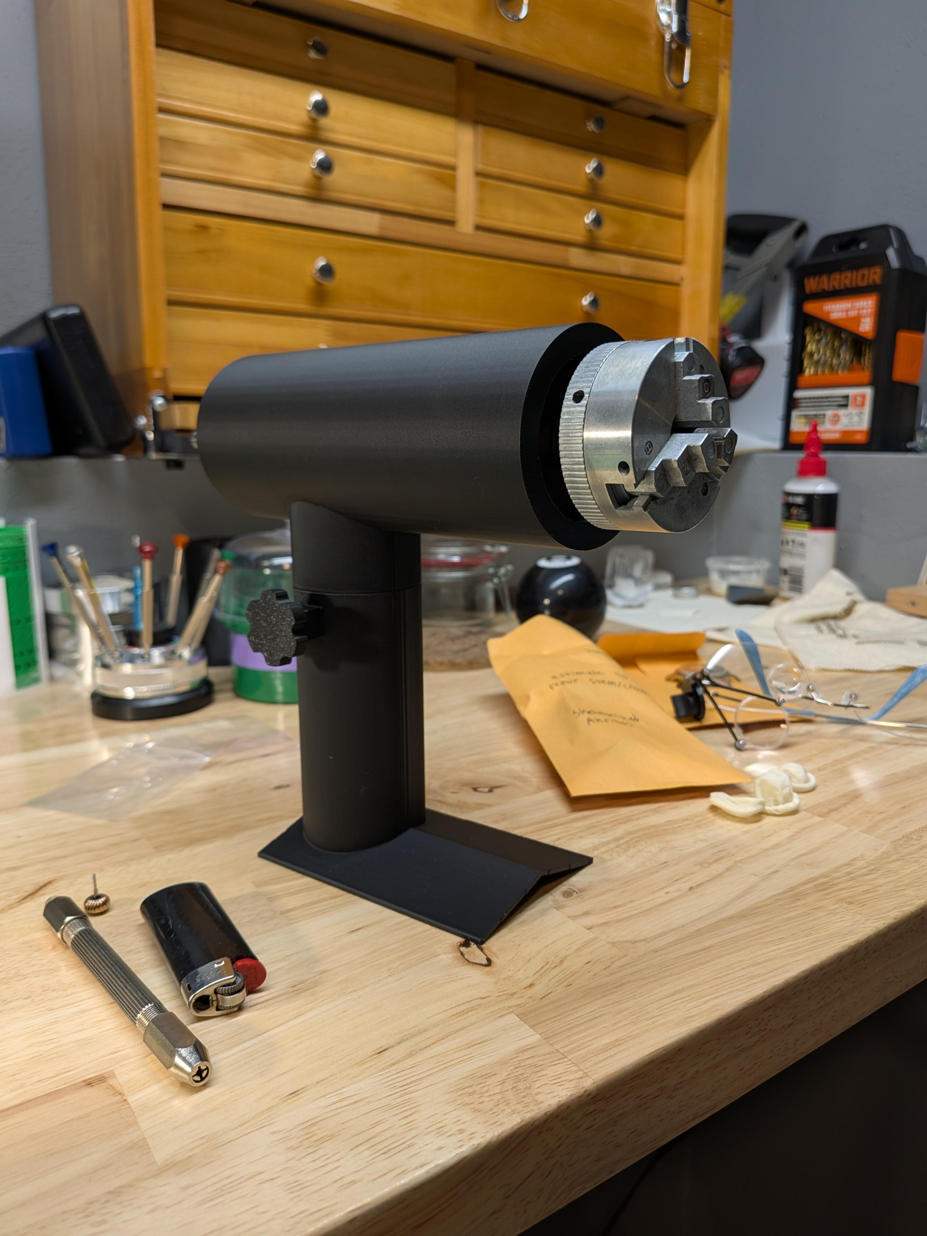
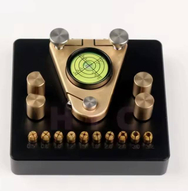
Partly as an experiment to find out whether we can still get these deliveries in the USA, I ordered a screw polishing frog. I'd been meaning to try to build one myself but am missing half the tools I'd need so I'll give this a gamble at a little over $100. Look for a review if they succeed in sending it to me.
 1 point
 -
I use an ancient and slow Lulzbot Mini with an upgraded extruder. I print horological related stuff all the time. Printing something now! I am not particularly fond of that style of screwdriver holder. I like mine lying flat. But, nevertheless, yours looks quite fine! ...and am well north of retirement age...btw
 1 point
 -
I'd say they both appeal to a specific type of person, and if it wasn't for the generational gap between your average watchmaker and 3D printing enthusiasts I would expect many more to have them.1 point
-
Still nothing from Mark. I sure as hell want to know what is going on. I'm really pissed off.1 point
-
I once spent HOURS with this... But for me, it wasn't about the crown position (which I had pulled out as instructed), but that I used a pointy probe to depress the "button". That allowed me to push it down to far and dislodge the keyless works. If one uses a screwdriver that fits the entire width of the slot (I believe it was the 1.2mm one), you are safe. Lucky you!
 1 point
 -
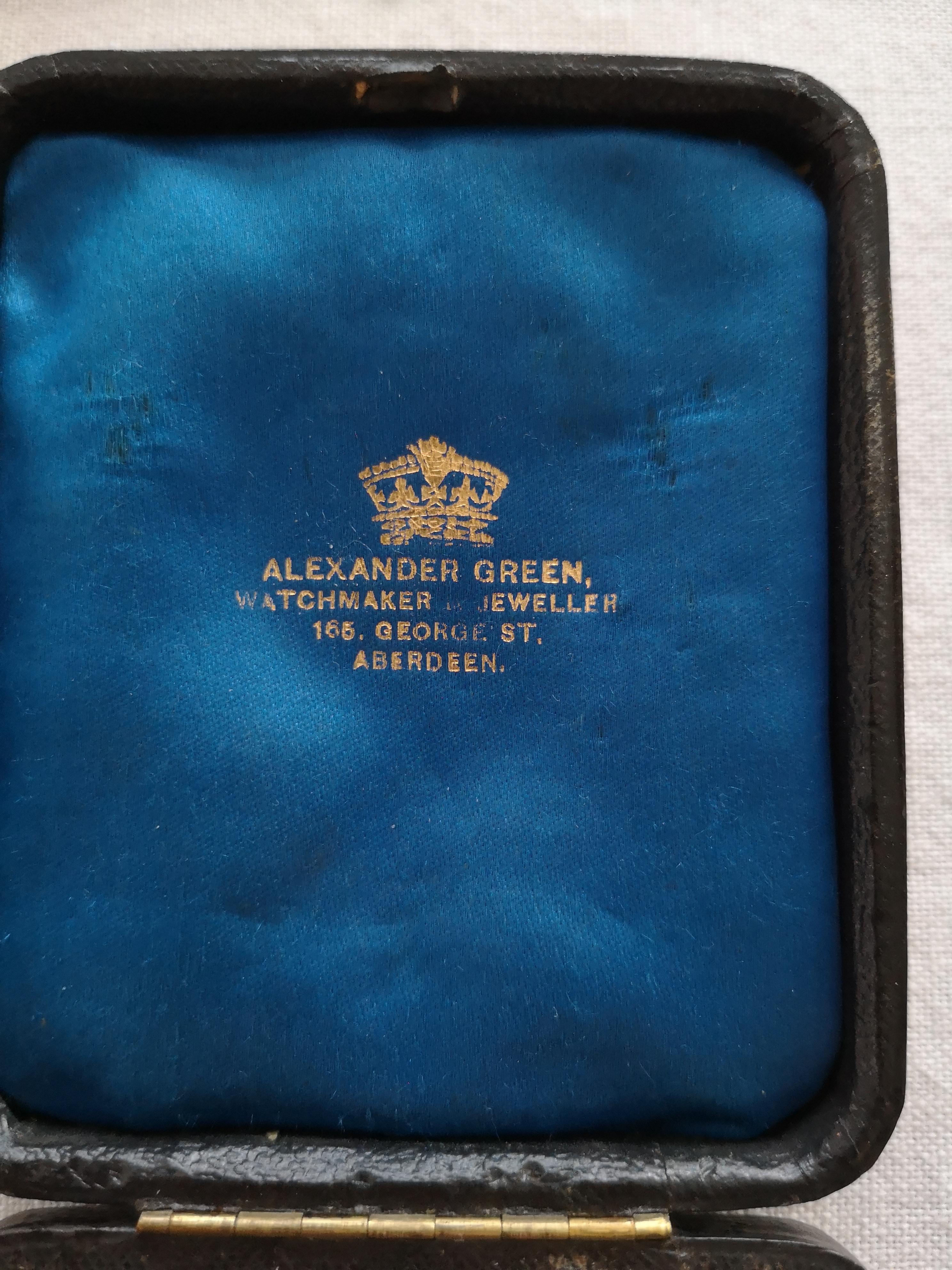
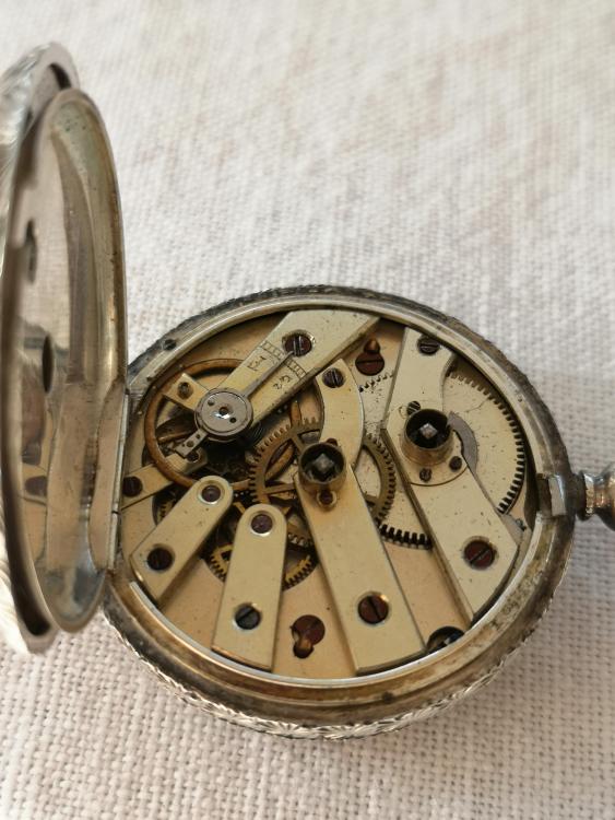
Good evening I am currently working on what I believe to be an old Scottish pocket watch. It is in a watch box with the velvet lining marked Alexander Green Aberdeen. The watch itself has no makers marks or calibre numbers or origin markings. The watch wasn't running right so after stripping it apart and giving it a thorough clean I noticed the mainspring is passed it's best so have ordered a new one and that the third wheel pinion pivot is broken. The watch looks like it had it's last service performed in a butcher shop as it is in poor nick. The enamel dial has been damaged and the 3rd wheel bridge has the jewel all cracked so assume the damage to the pivot occurred during the last reassembly of the watch. I normally am able to order spares for older wristwatches and newer ones because of the calibre numbers and makers marks being on main plates etc so not an issue but I have no idea where to start when looking for replacement old pocket watch parts like wheels etc. I know in the times gone by that Generale books were used. Is there a modern day version of this where you can order spares by size and dimensional comparison or has that ship long sailed? I would like to learn how to source parts as I really enjoy fixing the pocket watches that people bring to me. Any help will be greatly appreciated.


 1 point