Leaderboard


Popular Content
Showing content with the highest reputation on 03/08/25 in all areas
-
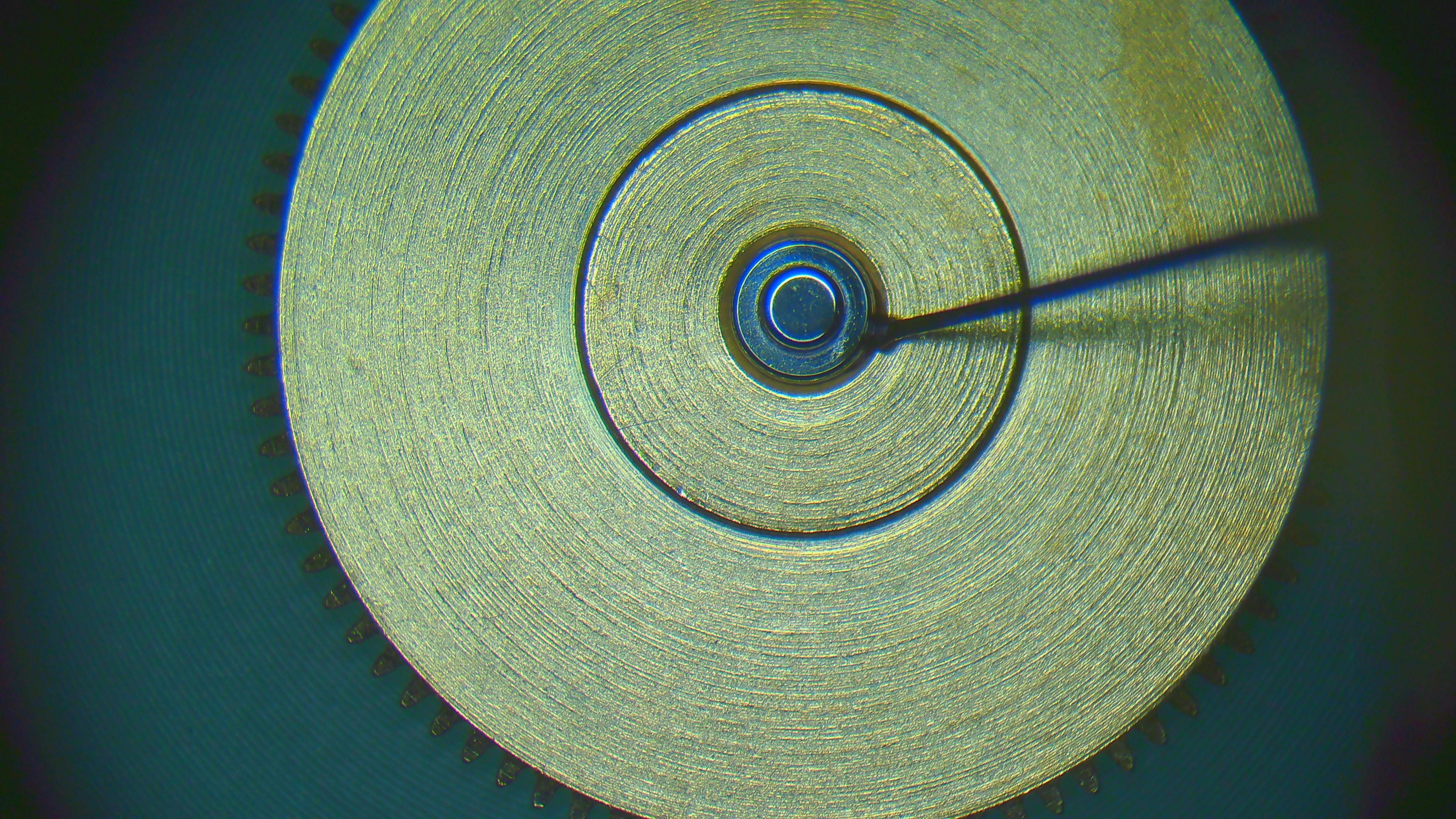
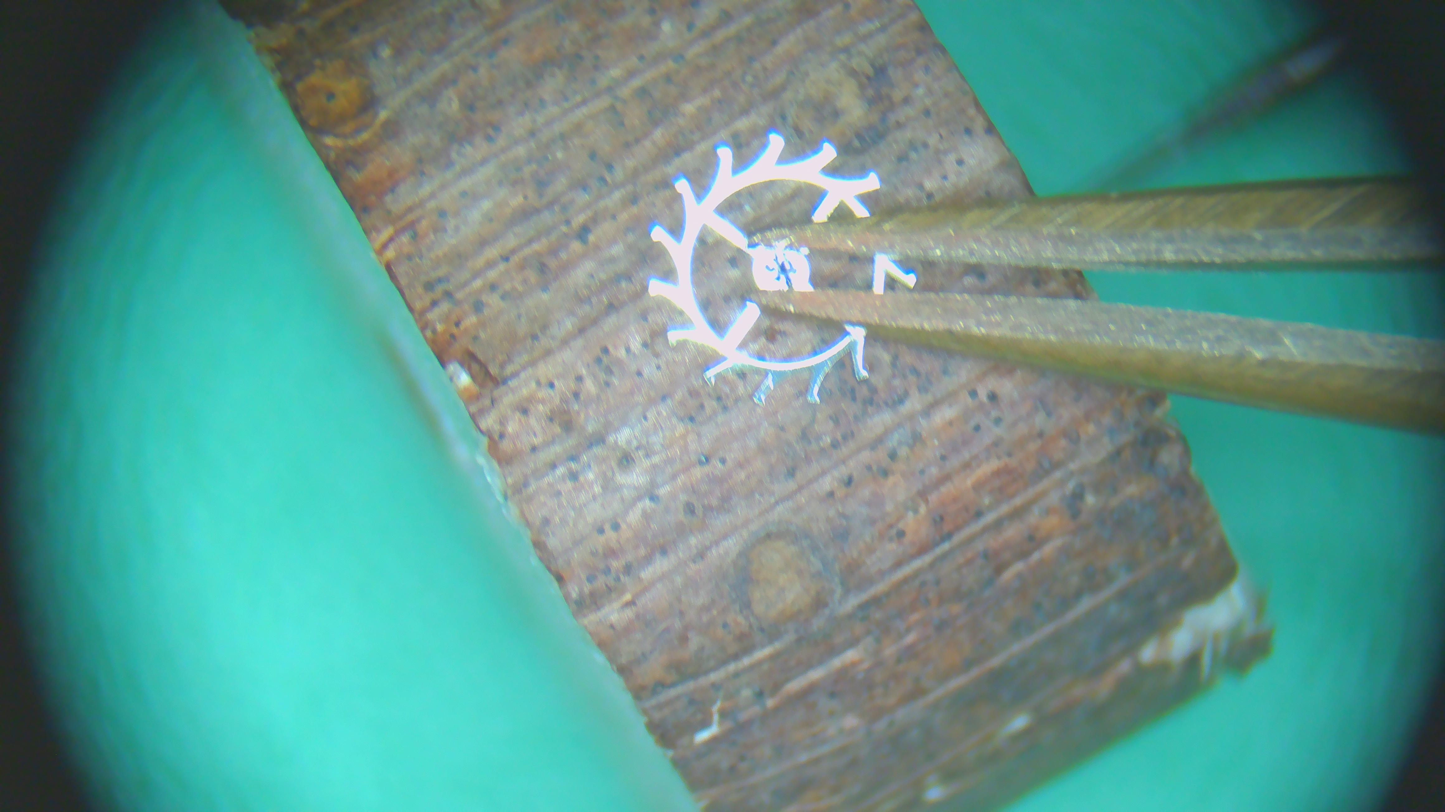
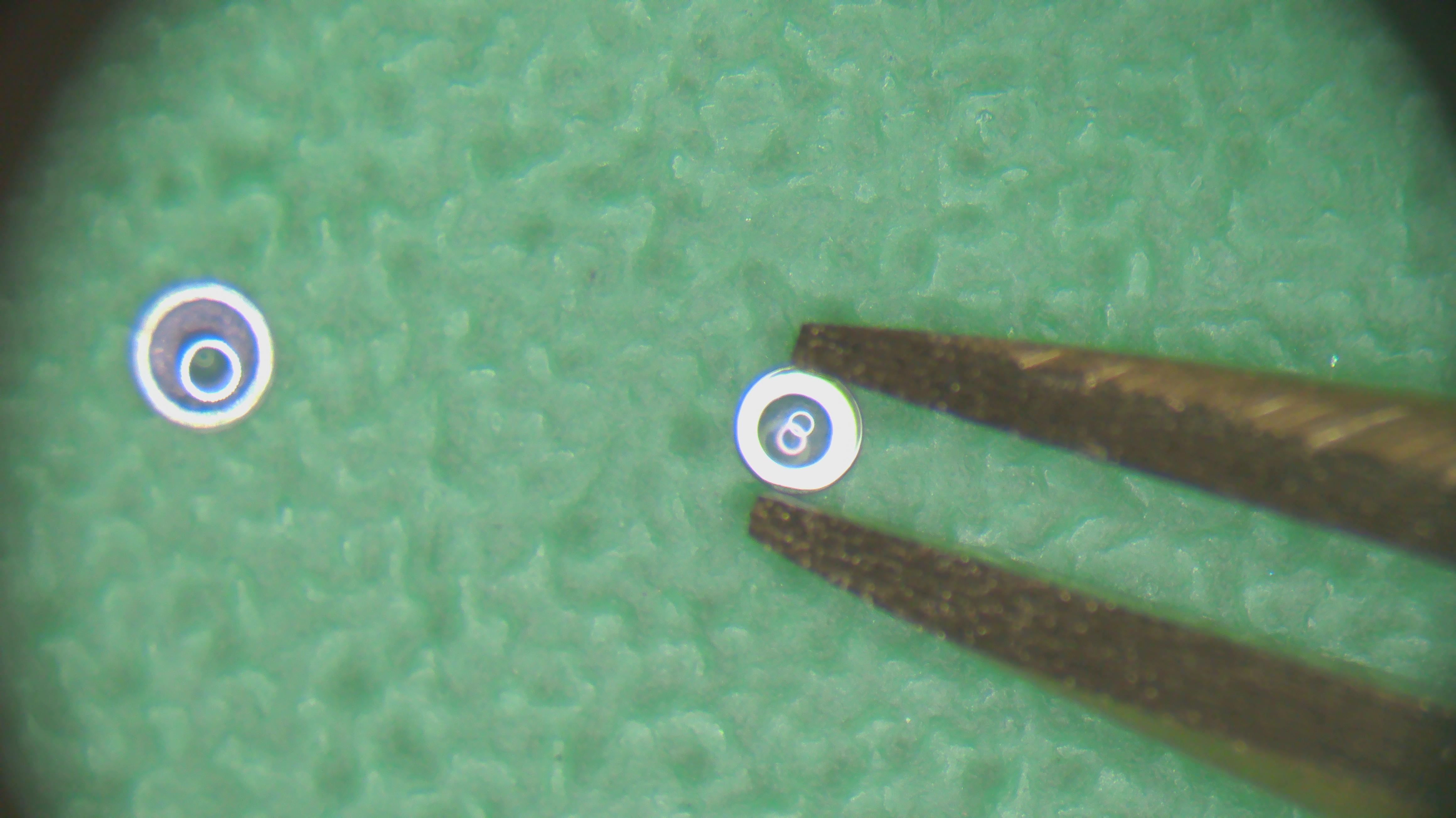
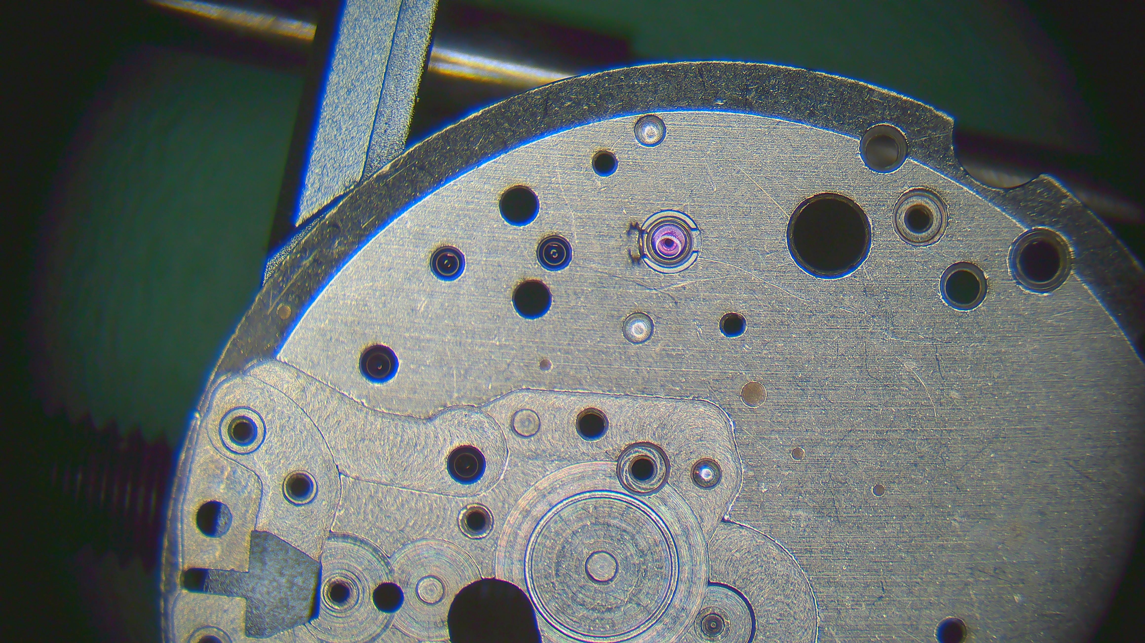
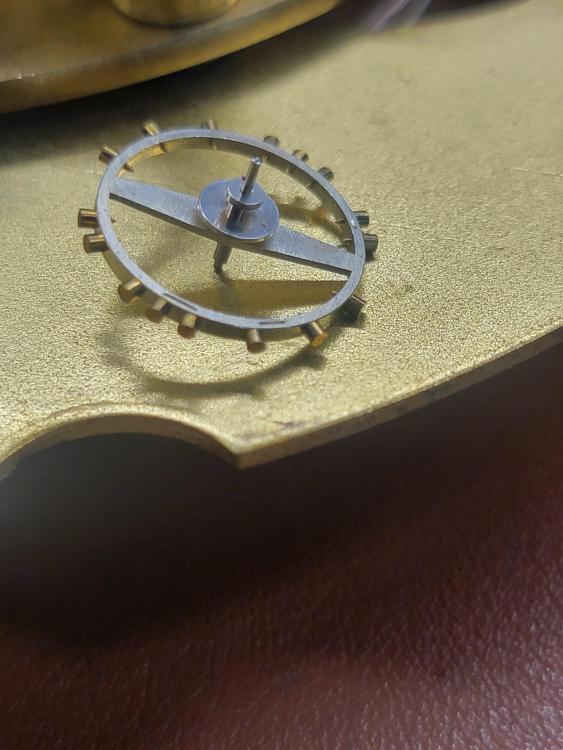
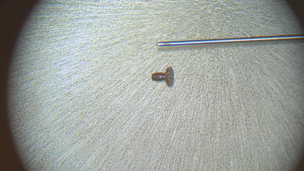
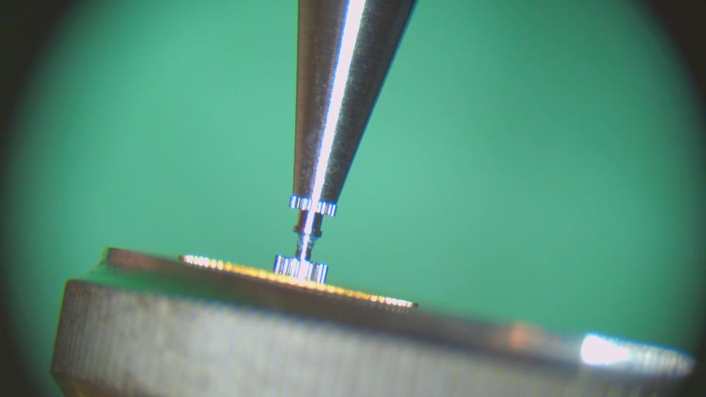
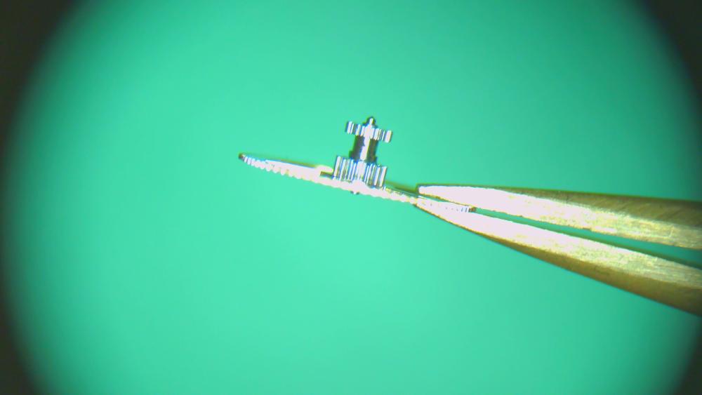
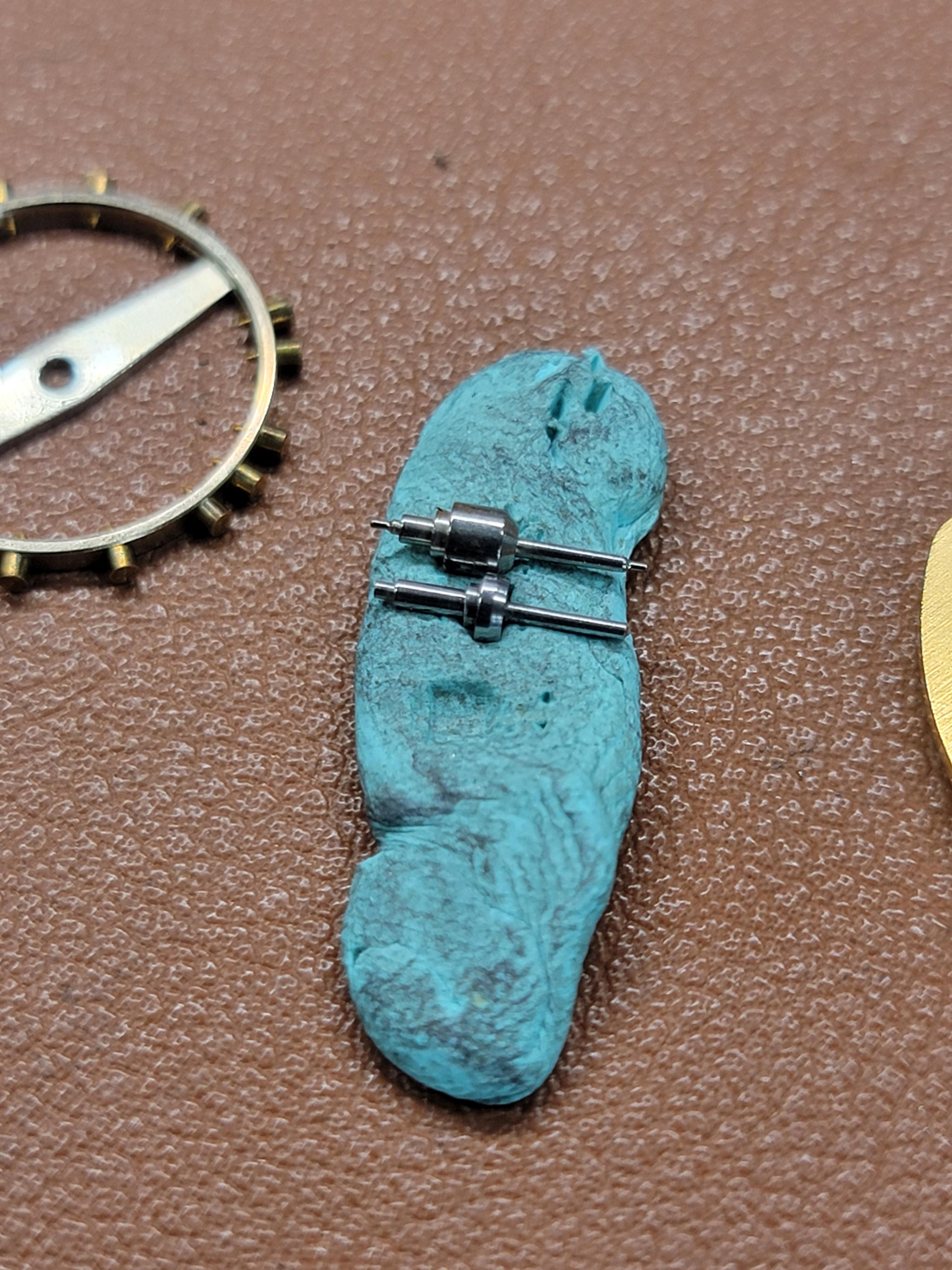
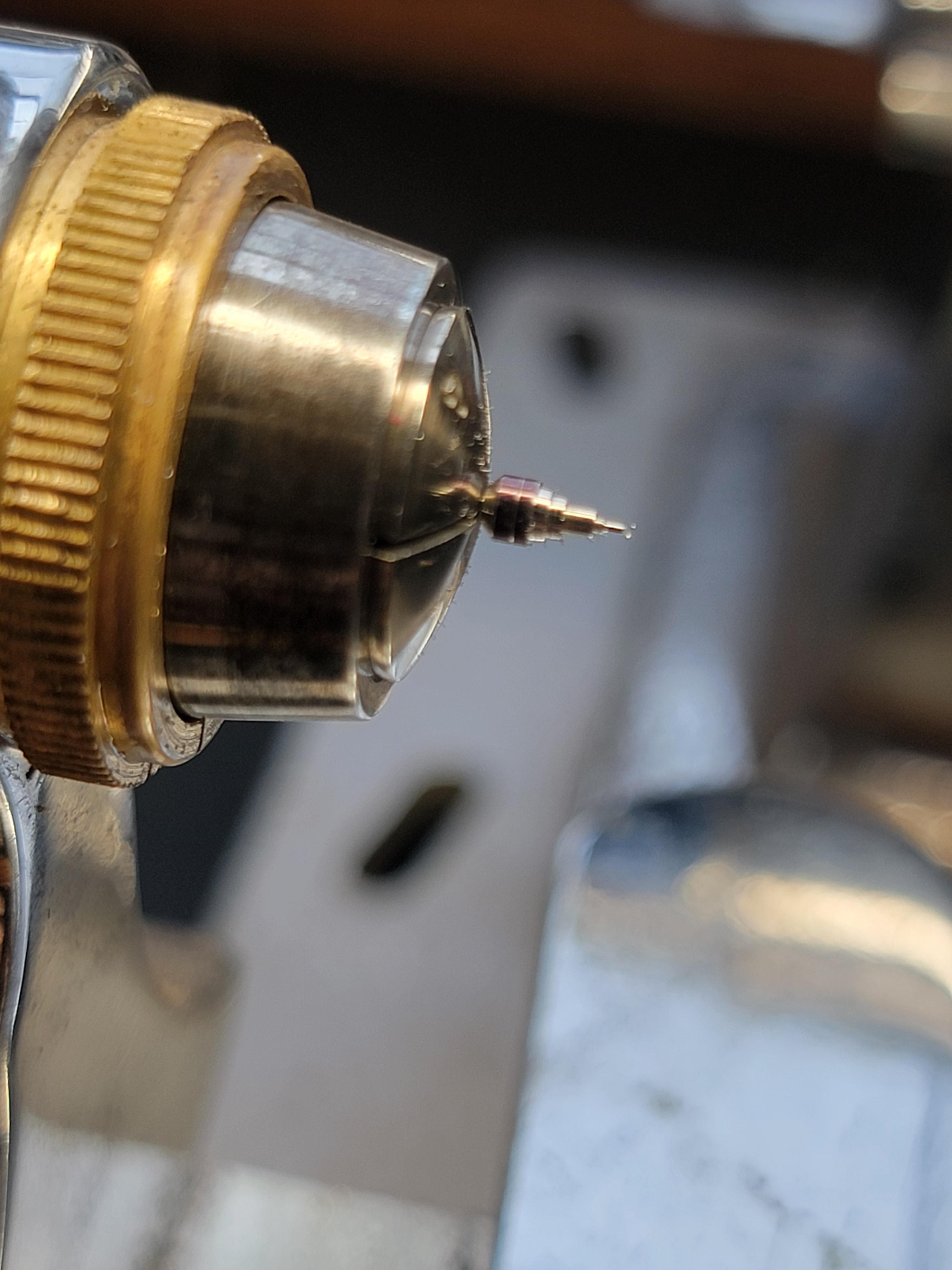
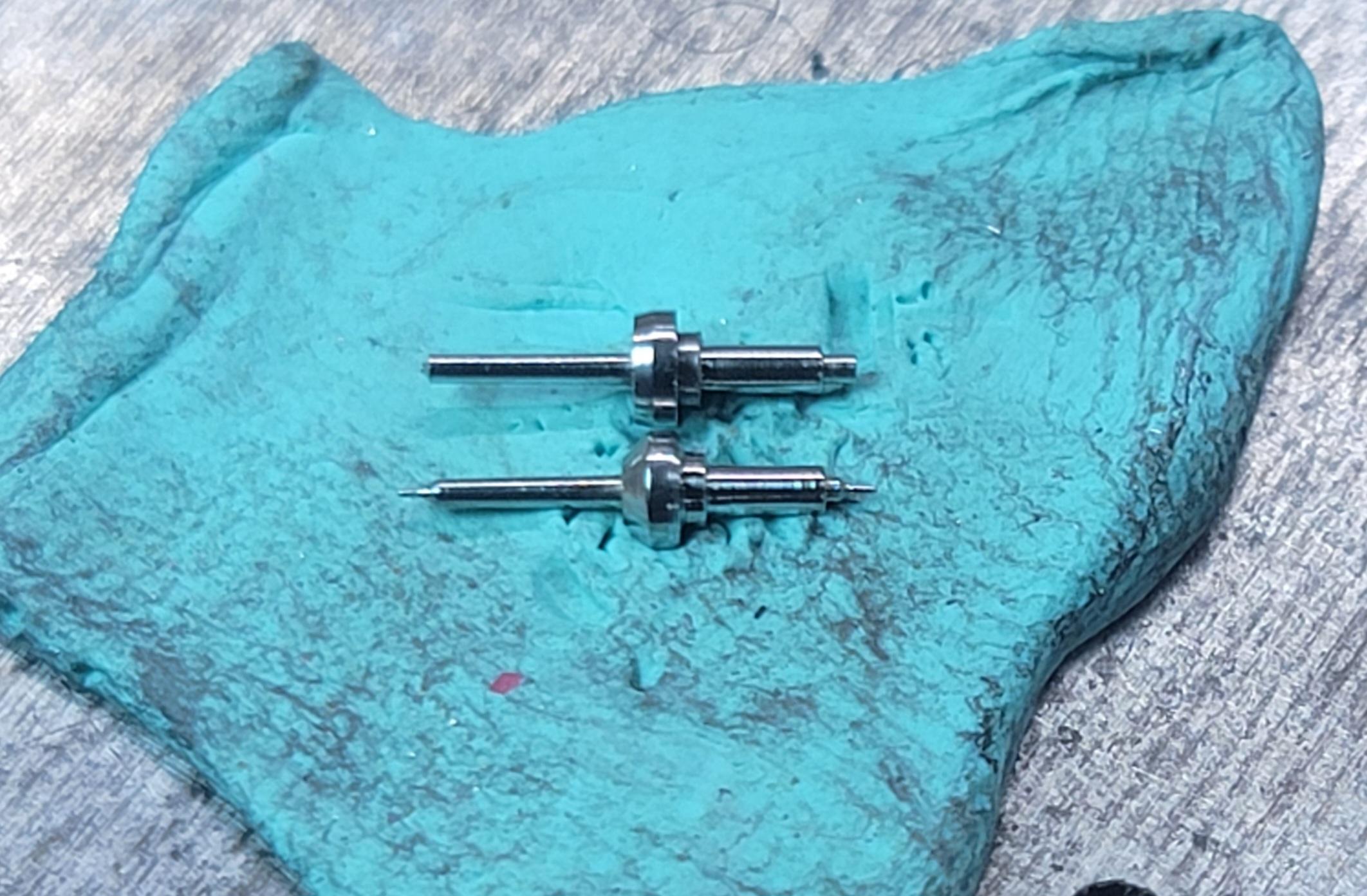
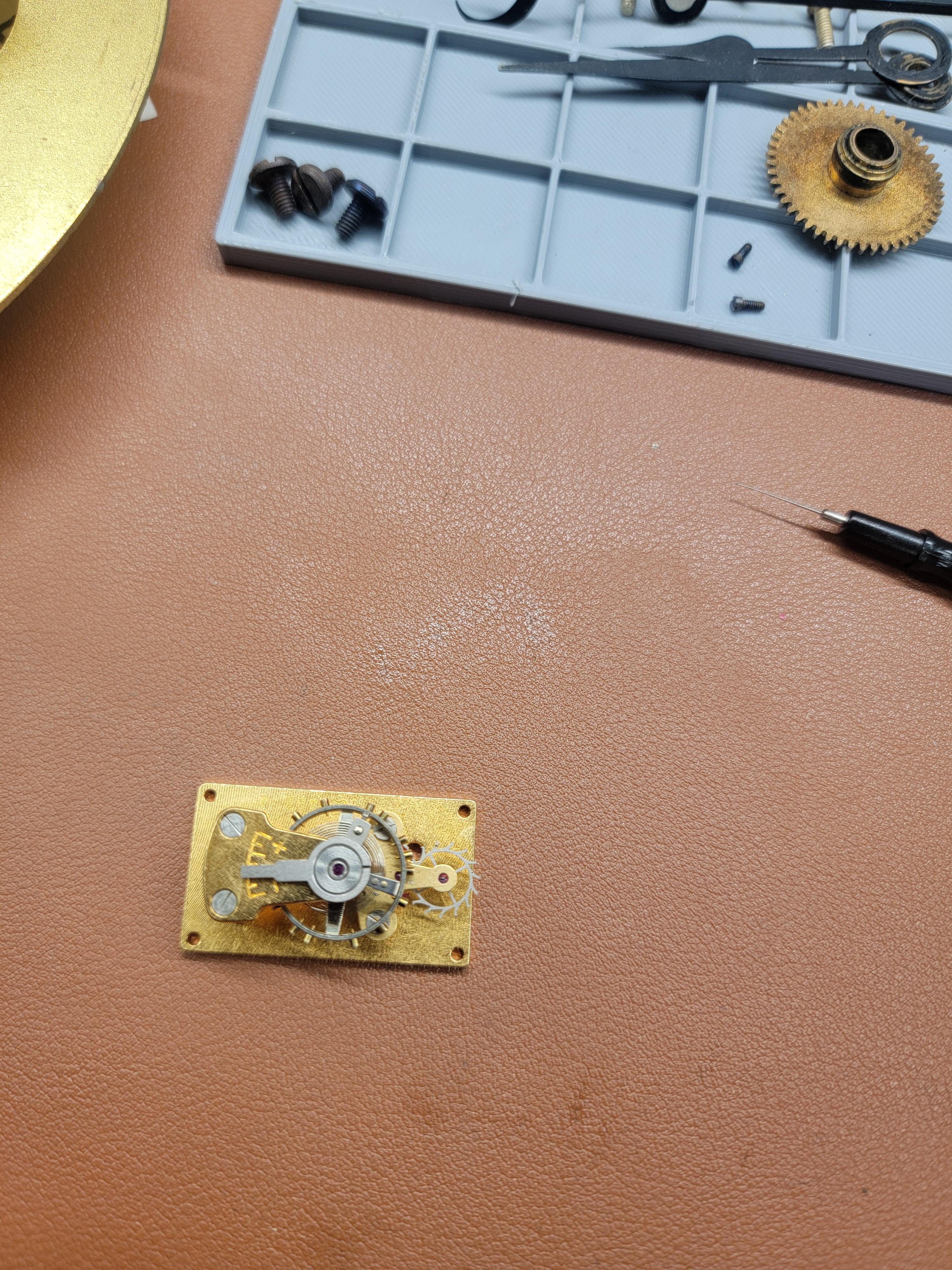
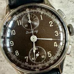
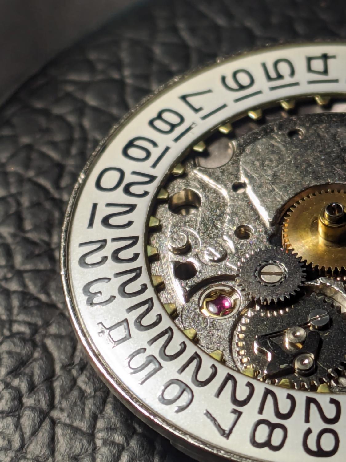
Picked this up for $80 at a little antique shop. Said it was running--not! Broken balance staff and bodged mainspring. I looked around for a staff and could only find staffs that were about 6mm long. This one is about 8mm. Both pivots were broken yet there is no indication the clock was dropped. We'll, I could see deep pot marks around the edge of the balance jewels on the plate. Some numb nutz was just forcing the balance until it broke. With little hope of finding a staff, I made one. I started with a larger PW staff. The escapement platform is assembled and my free spin test was excellent. I am repairing the MS arbor, so until that is done, I cannot test operation.


 5 points
 -
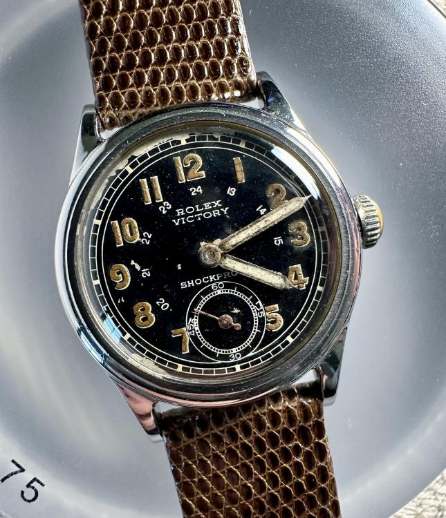
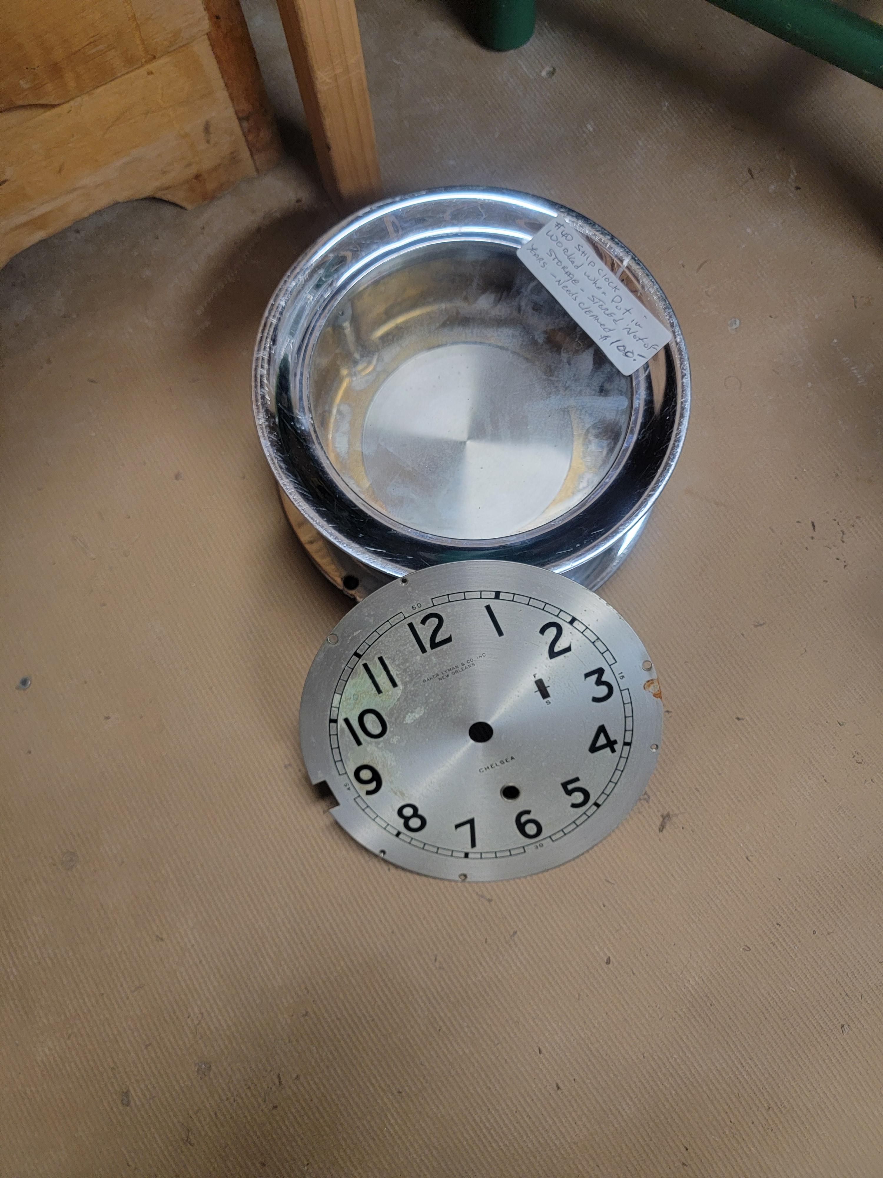
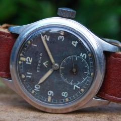
My advice would be to either leave as is or take to a professional as any attempt to clean the dial is likely to make it worse.4 points
-
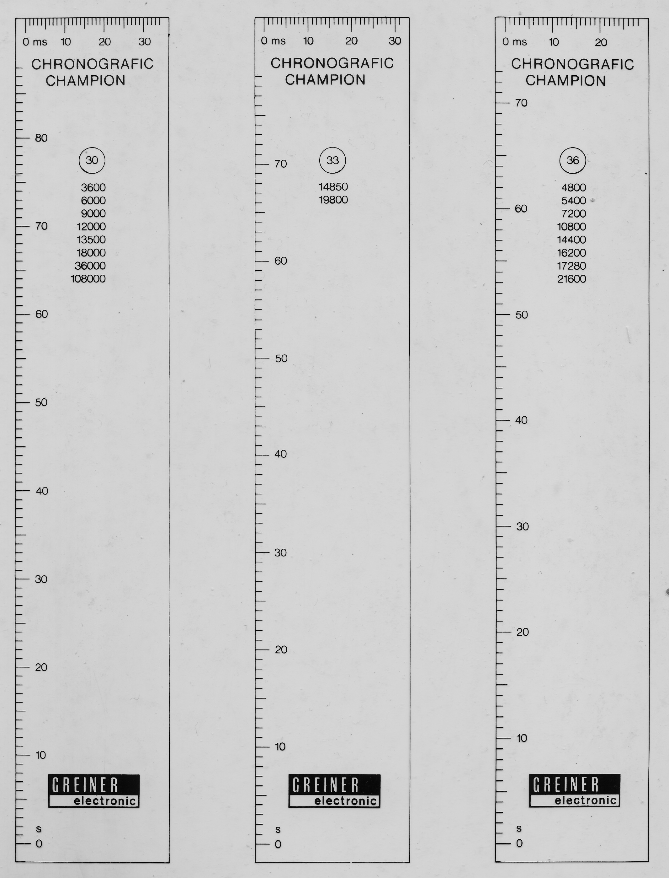
Sometimes yes. You can find out yourself. Usually the manual tells the rotation speed of the drum, e.g. f=30 Hz @ beat x. The width of the paper equals 1/f sec. From here you can find your beat error. Frank3 points
-
Added this PDF to my stash. Sooner or later I will have collected all the world's knowledge of watch parts & tools through @JohnR725's slow drip of forum post document dumps. I had no idea Bergeon sells separate winders for the two 6497/8 models.2 points
-
I'm I in your thick club as well. Don't forget I'm a mod.2 points
-
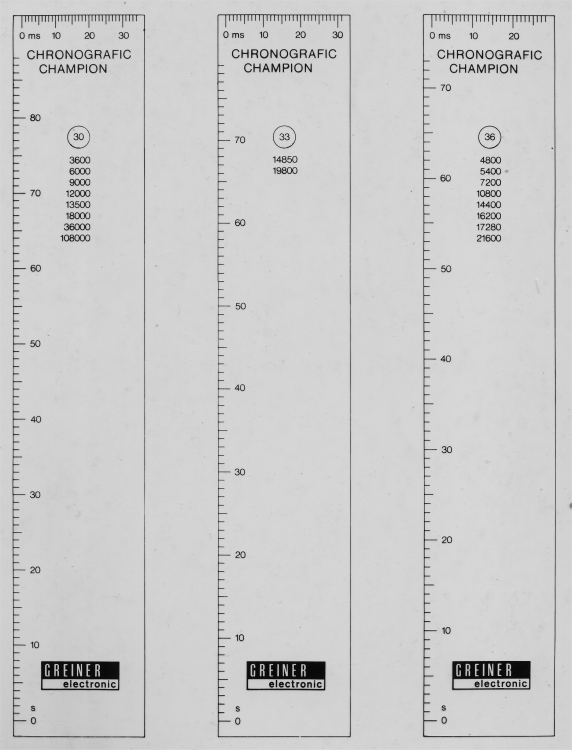
In John‘s picture, left paper: drum rotates @ 30 Hz (see circle). That is the speed, if shown beat rate group was selected. Assuming the paper width is 33mm. Then the paper width equals 1/30 s = 33ms or 1mm equals 1ms. If the paper is 40mm: 1mm equals 33ms/40mm * 1mm = 0.825ms If nitpicky, replace paper width by printing width, if not the same. You can make cardboard rulers for your machine like Greiner showed.2 points
-
The amusing problem is the service manual does not specify a timing machine. Not specifying an exact timing machine considerably that would be some variations but probably on paper tape machines they're all approximately the same. So that you don't have to do the math I've scanned the transparent ruler that comes with the Greiner timing machine manual. Although I don't see the frequency we need which is 28,800. Which I believe would be the one labeled 36 although I am mathematically challenged so Frank may have to verify that that is indeed correct. I'm also attaching the service manual at least what there is of it in PDF form. Then for those nitpicky observant people of exactly how big is the image versus the original image I will measure the last one Number 36 5 mm Is equal to 4 ms exactly. 3540_ETA 9154.pdf
 2 points
 -
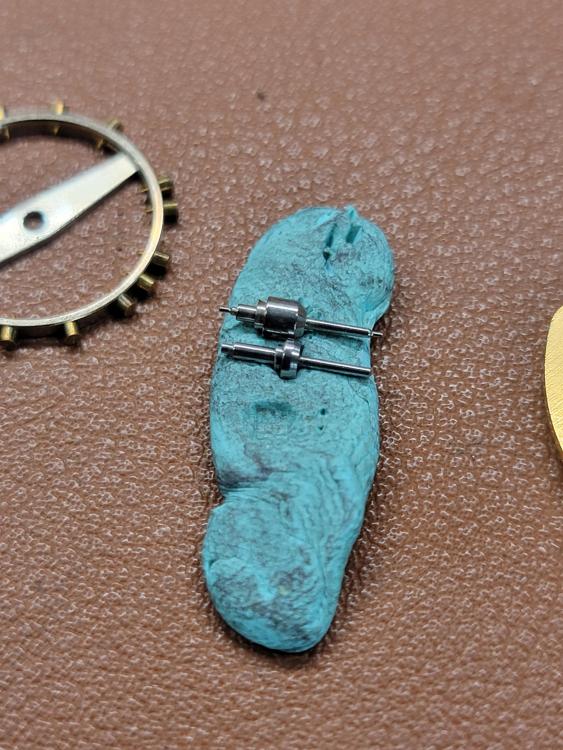
The problem is 6498 is not the same watch is a 6498 – 2. Then there's the problem of parts listing later generation ETA watches don't typically have mainsprings listed as you're supposed to replace the entire mainspring barrel. And often times the mainspring listing doesn't seem to show up anywhere. Although it looks like I'm wrong according the cousins they're exactly the same By we do end up with this weird problem if the mainsprings are exactly the same then why do we have to have two separate mainspring winders? Then someone was kind enough to make a nice PDF of mainspring winder sizes snipping out a image brings up the peculiar problem of the center part for the arbor is not the same size as the handles not the same size? I'm also attaching the PDF. Then the other thing is interesting is for mainspring looking at ETA because of course the Chinese don't list parts anywhere in the universe and we don't exactly know how exacting they clone things. In a case looking up the parts listings we find out that the barrels are different between the two types and the arbors are different and bestfit disagrees with cousins as to whether there even the same mainspring Unfortunate problem of best fit on line is you get part numbers you do not get specifications but the indication is the mainsprings a be different. HJ-Mainspring-Winders.pdf

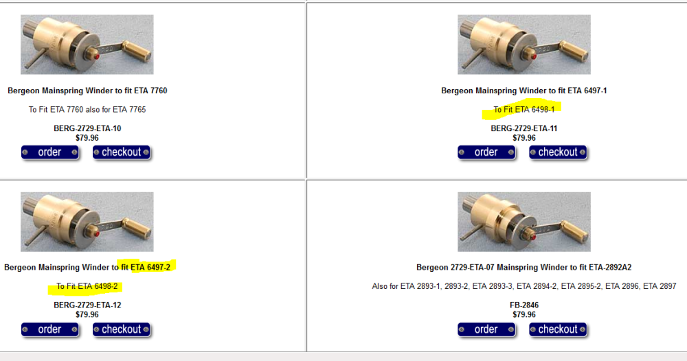

 2 points
 -
We do appreciate your teaching OH, unfortunately we are a bit thick. How do you think we got to be moderators? Tom2 points
-
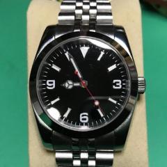
Welcome to the forum. This could be it.
 1 point
 -
I have moved this to a more appropriate section @Sal Tom1 point
-
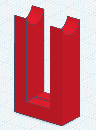
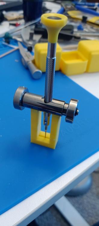
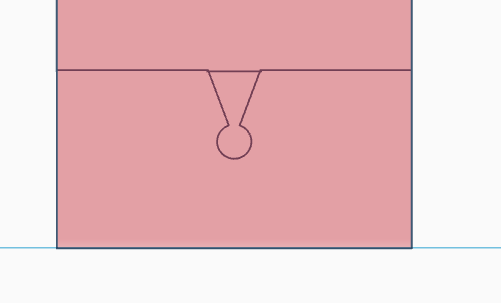
I recently purchased some surprisingly high quality screwdrivers from AliExpress that have the exact same design as the Bergeon 30081 series, but at a quarter of the price. Unfortunately, the blades tips were flattened too much during manufacture, which meant that I could barely use anything other than the 0.6 mm to 1 mm screwdrivers, because the blades wouldn't fit into any screw slots. I've sharpened screwdrivers in the past, but I've never done it very well. The angle of the wedge was never quite the same, and I couldn't never quite get the orientation correct, meaning that I was cutting a new blade face rotated by a few degrees rather than sharpening the existing one. I have the Bergeon screwdriver sharpening tool holder (https://www.cousinsuk.com/sku/details/screwdriver-sharpeners/s1521?skuId=26987). The problem is, when sharpening, your screwdriver blade angle will change depending on how far into the holder you place your screwdriver. If you put the screwdriver in too far, your blade angle will be very narrow, travel further down the shaft, and the blade will be very thin at the tip, possibly risking breaking. Not far enough, and your blade will be fat and you won't be able to fit the tip into any screw slots. So, I endeavored to create a solution... Judging by the picture of the replacement blades, the tip angle looks to be 26 degrees total included. The goal here is to then create something which limits the length of screwdriver that you can insert into the sharpener, and which results in the screwdriver sitting at 13 degrees to the horizontal. Without getting into the trigonometry, you need to extend the screwdriver about 30 mm from the sharpeners pivot point in order to reach 13 degrees. I sketched it up in Tinkercad (attached picture). The curvature of the sharpener fits onto the top, and the screwdriver points down. There is a V-notch at the bottom that orients the blade so that you're always resharpening the existing faces of the blade, rather than having the blade rotated slightly, which would cause you to cut a new face. And I'm happy to report that it worked extremely well, probably within 1 to 2 degrees of what I calculated. The blades were sharpened precisely over the old face, and the end was perfectly perpendicular. And that 1-2 degree error is not down to a lack of theory, but rather the realities of 3D printing; that you'll always get layer lines, and that corners can never be truly sharp. I think what was happening is that in the initial version, the blade-orienting slot was designed as a sharp V-notch. But since 3D printers can't print infinitely sharp slots, the screwdriver didn't fit into it exactly as intended. So I made a follow up version (haven't tested it yet) that includes a small recess at the bottom of the V to allow the very end of the blade to fit in. If you would like to try it, the file is available at https://drive.google.com/file/d/1mWjxi0HUs9jL55ysQaSV2xnyMiAOS29Y/view?usp=drive_link. Just note that this was built to fit the Bergeon screwdriver sharpener. Other brands might have different geometries which might result in different blade angles, though I don't think this will be so drastically different.
 1 point
 -
Thank you. For the longest time I was using a set of cheapo Indian screwdrivers, which I had eventually swapped Bergeon blades into. They never gave me a day of trouble with slotting into screws so I figured I'd just emulate what I already knew worked.1 point
-
I may be mistaken, but I don't see any lume on the dial or hands. Just for peace of mind keep your fingers away from your face, wash your hands afterwards and wipe down your work area. You'll be fine.1 point
-
Nice work it’s amazing what you can do when you have to.1 point
-
I don't think Tom forgot. Hehe.1 point
-
Dials like that leave to the professional dial restories.1 point
-
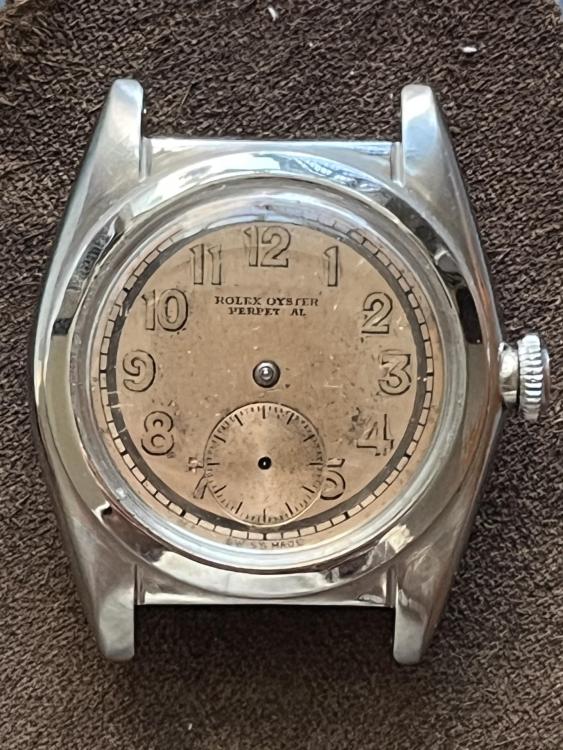
…it may difficult for some to appreciate but a dial that has aged as gracefully as this is very desirable by many collectors (as is the ‘suiza’ designation)…and as recommended above the movement, case and a light polish of the hands will freshen everything while still maintaining coherence…this heavy patina Rolex I have is a very modest watch but receives outsized attention at places where expensive watches prevail… …this is a thread where dial restoration was discussed in detail. Hope it is constructive for your Longines…
 1 point
 -
It's important to understand that most of that discolouration isn't dirt, it is irreversible staining caused by chemical processes in the paint and lacquer. No substance in the world can remove it, and an incautious attempt will ruin it. I think it has aged in a dignified manner and would polish the hands and crystal but leave the dial alone. If your brother is not happy with it, then the only real alternatives are replacement or refurbishment. A lot more can and should in my opinion be done with the case and movement.1 point
-
No 5ms is the time difference between the impulse reaching its dead on beat point, from one beat to its opposite beat. The distance travelled difference will change depending on what the amplitude is at that time.1 point
-
The simplistic answer would be no. Typically with the paper tape timing machines they did not tell you that X number of millimeters equals so many milliseconds. I have only seen one manual that does have a scale that tells you how many milliseconds corresponds to their ruler that they include. Then the milliseconds spacing will change depending upon which rate you're on.1 point
-
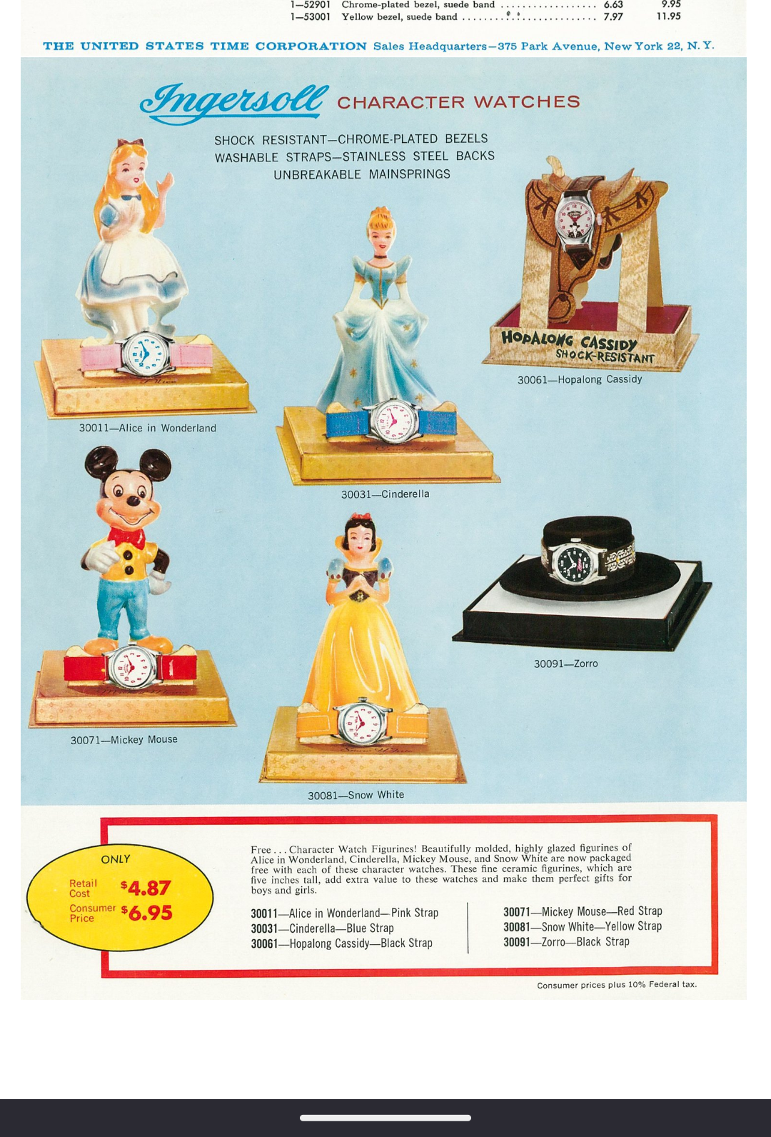
I somewhere have a bag of red hands for the Hopalong Cassidy watch, it is probably the same as the other red ones. I have restored a few Hopalong Cassidy Timex watches.1 point
-
@AndyGSi I remembered these with dials similar to yours in the early 60s Timex catalogs
 1 point
 -
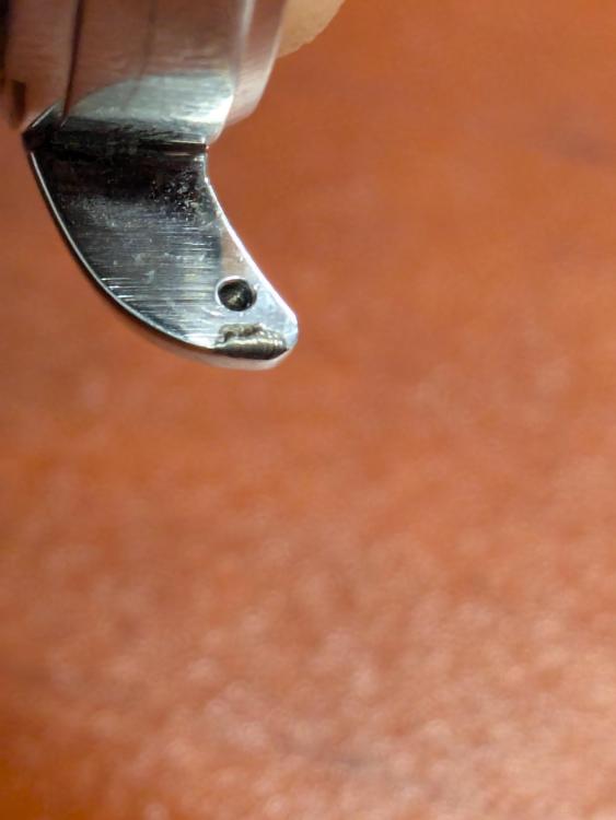
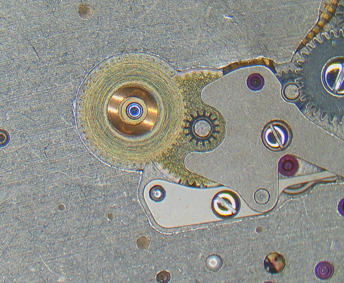
Do I see a bush instead hole jewel for balance in the plate?1 point
-
The only explanation I can think of is when the original damage was done to the boss the bridge has twisted and that's what's jamming it. I think the problem is they don't have the knowledge or experience to risk digging into the movement further.1 point
-
Thank you so much. Yes tricky to get started but knowing that I was on the right track was a big help. I got it wound back in and the arbour back in. The idea was to clean it and lubricate but I'll leave that and take the "win" for now! At least I know what I'm aiming at now. Thanks.
 1 point
 -
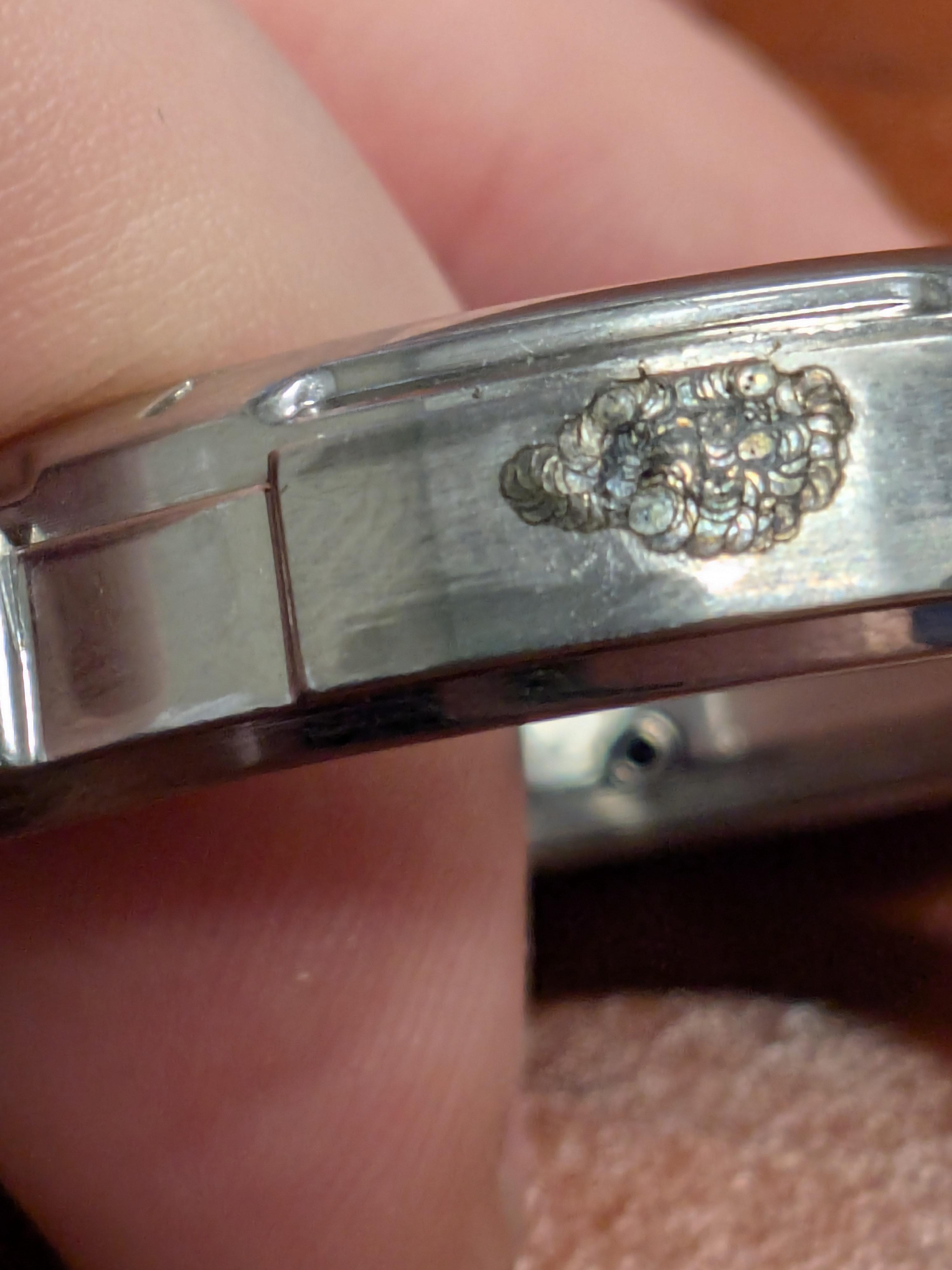
A little update. I haven't made a ton of progress on the setup, but now I will need to move faster as I have a case restoration on the bench. I did a little welding on it

 1 point
 -
Oh come on Richard chip in after all I tried to teach you have you forgotten all ready.1 point
-
I haven't commented on the clock because, I'm clueless too, but I have been following the post and will like so know what progress has been made.1 point
-
Hi there are organisations in America such as the AWCI and the NAWCC who like the British BHI will be able to point you in the right direction as regards finding the right people in your area who can restore your clock which will look superb once restored. If you contact either or both of these organisations I'm am sure they would be able to help.. Good luck in your endeavors and keep us posted on any progress as to how you get on. We remain interested. Cheers1 point
-
Thank you to everyone who has responded to my post I truly appreciate your help and guidance as I am clueless as most of you can tell. Everyone on this forum has been so kind I'm actually kind of shocked most forums are not like this. I live in Southern California if anyone knows of people that might be interested in helping me get this beautiful piece restored I would appreciate it. If not I just wanted to say thank you to everybody for your help comments and guidance hope everyone has an amazing rest of their week!1 point
-
I have been replying to this for LadyLost by message. It certainly is a Tavern clock early 1800's that you can be sure of by the size of the dial. The clock tax ended in 1798, but the design carried on but the size became smaller. The very early ones had very large dials. The name on the dial is the maker.1 point
-
nice 19th century English longcase stiking movement, as for the maker without my Brittens at hand I cant look up that name, although that may just be the name of the shop that sold it as opposed to the actual clock maker. Where are you located? also bear in mind that the case restoration will be a separate job to the service of the clock movement unless specified when price is given for work to be done.1 point
-
I hadn't responded yet because frankly I was at a mental impasse not sure how I wanted to proceed. I definitely knew that I would not have Peace of Mind with the watch as is. So I did decide to remove the radium myself which I finally completed. I'm the kind of guy that likes my vintage stuff to look used and abused so I actually don't mind the way the dial looks currently and may decide to just wear it like that once I redo the hands. Unfortunately no comparison to the cool looking dial it was before (choices, choices). However I am still debating whether to send the dial in and have it redone. To be continued.
 1 point
 -
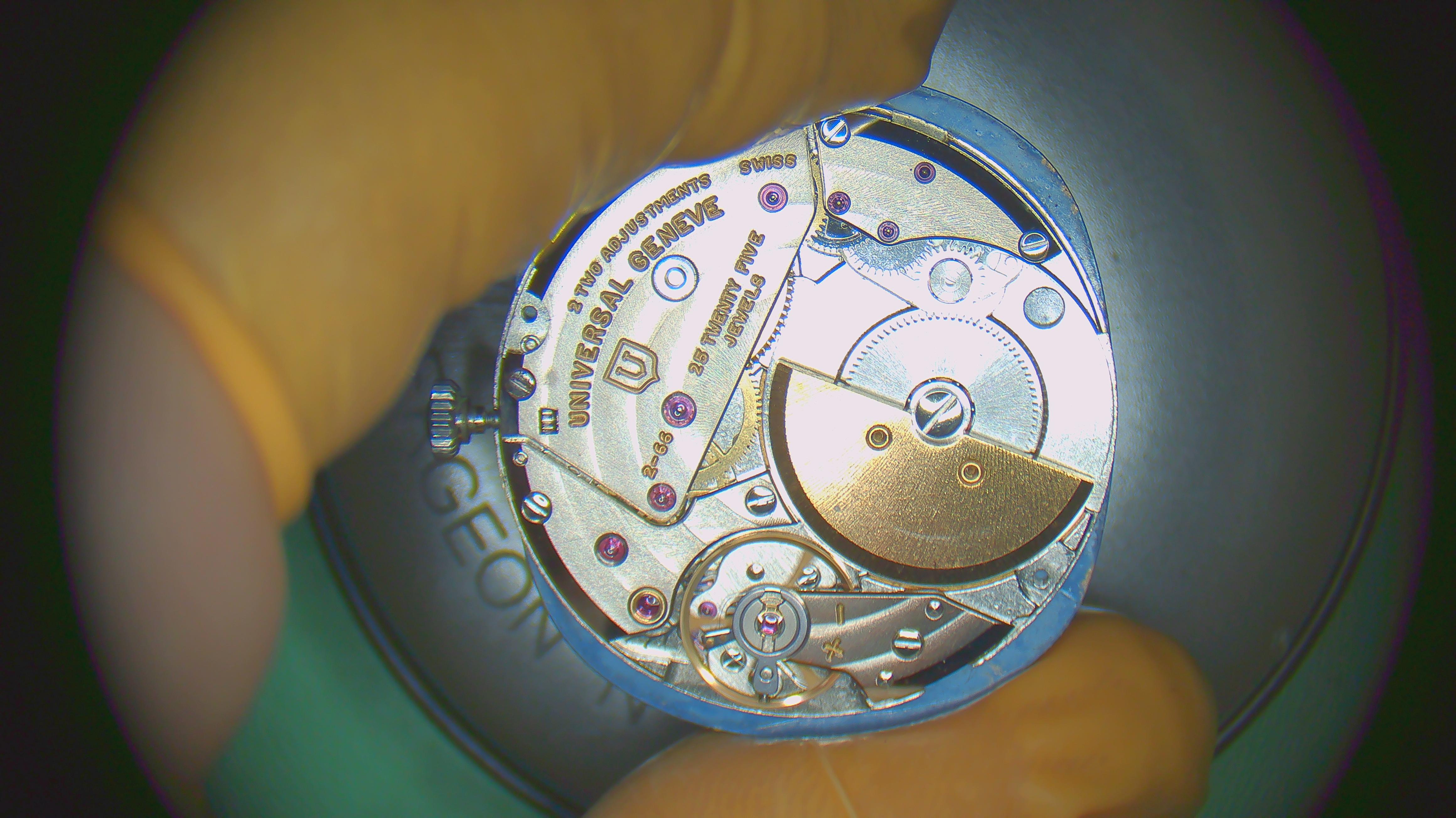
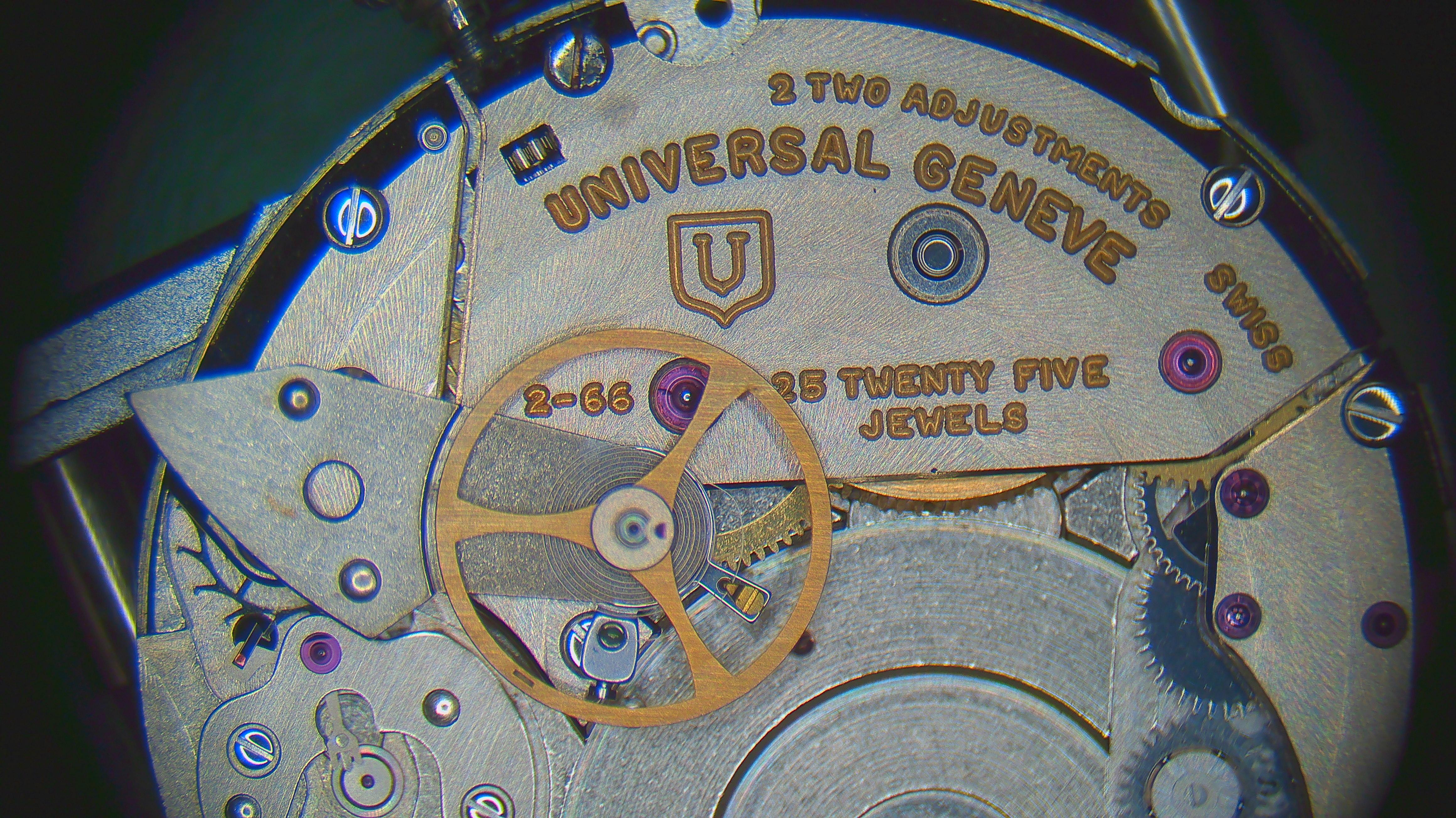
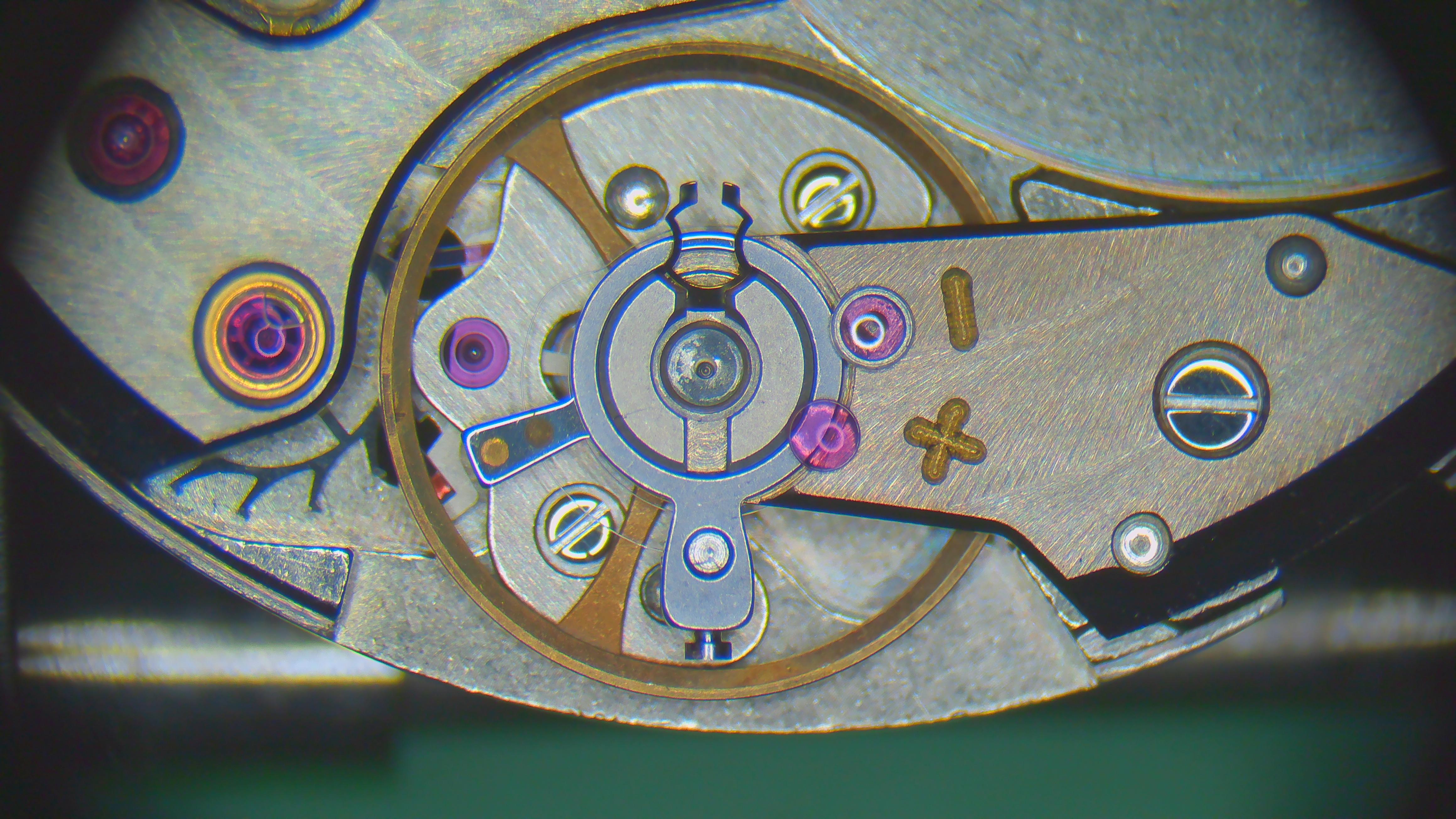
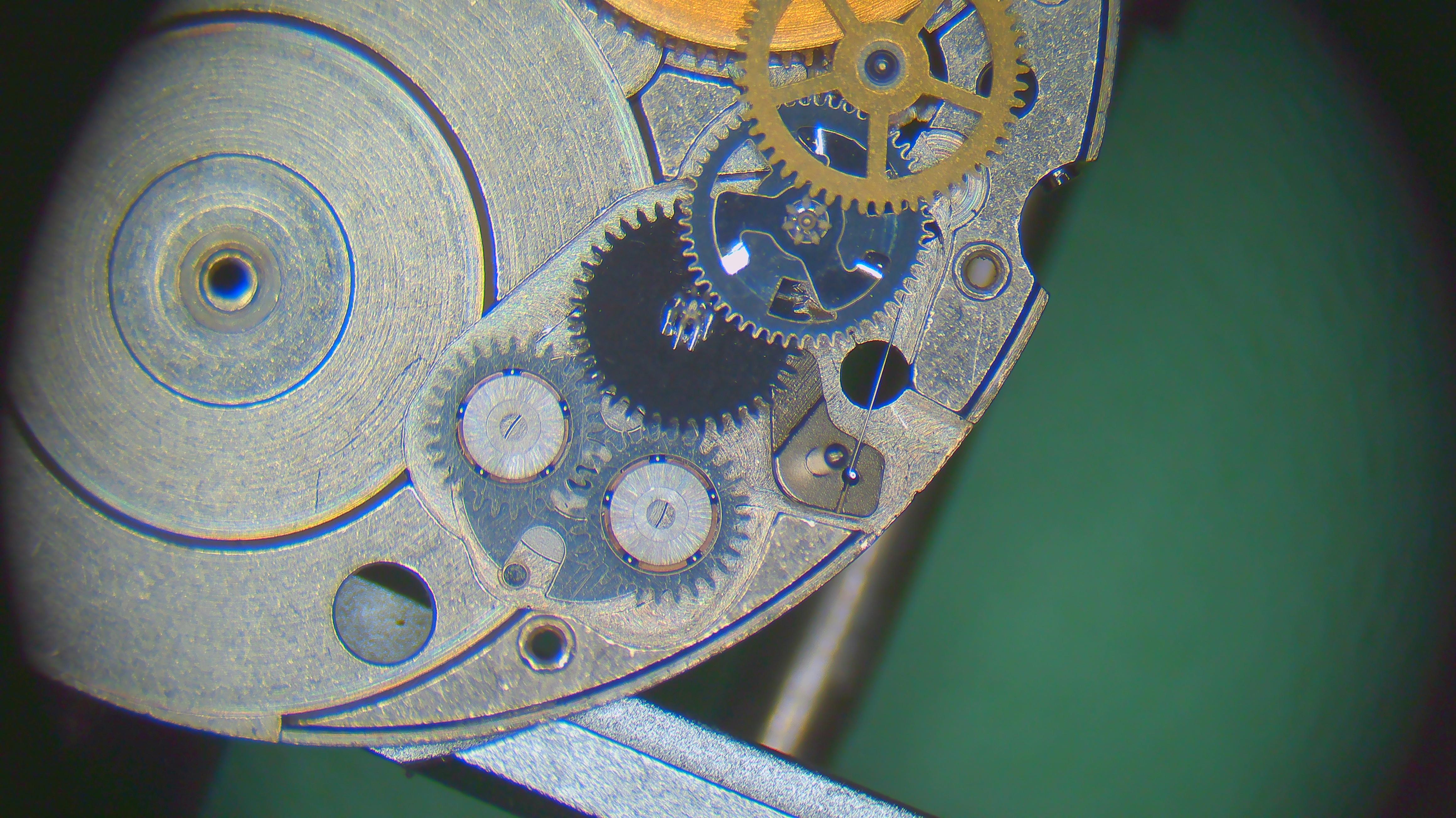
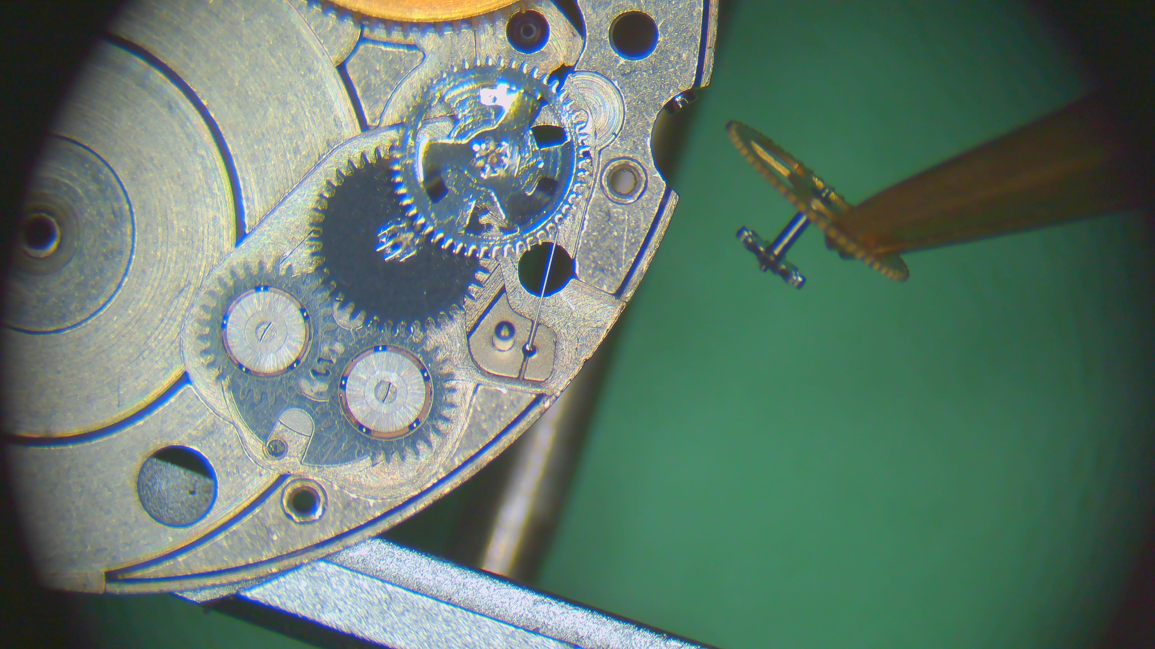
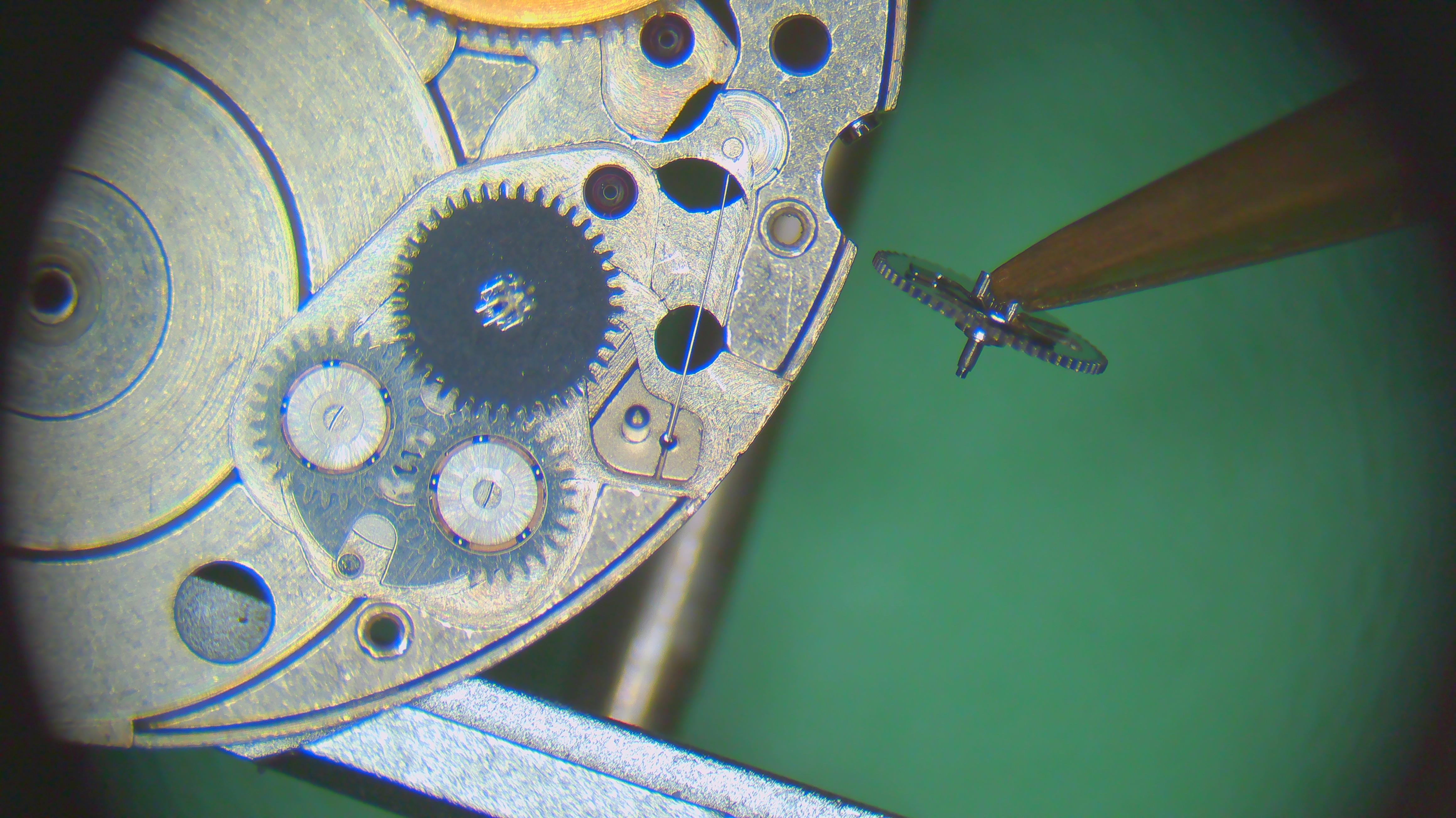
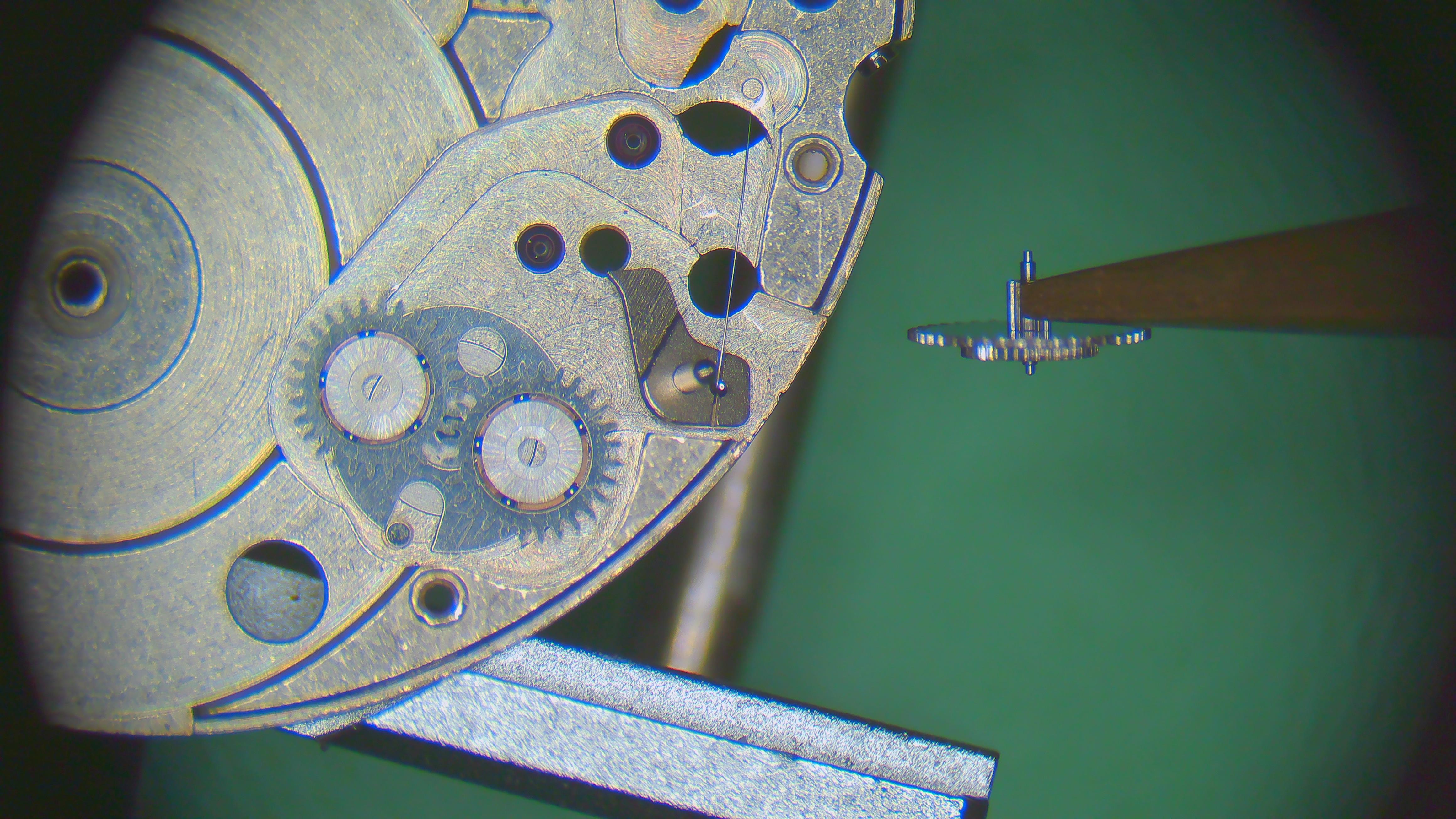
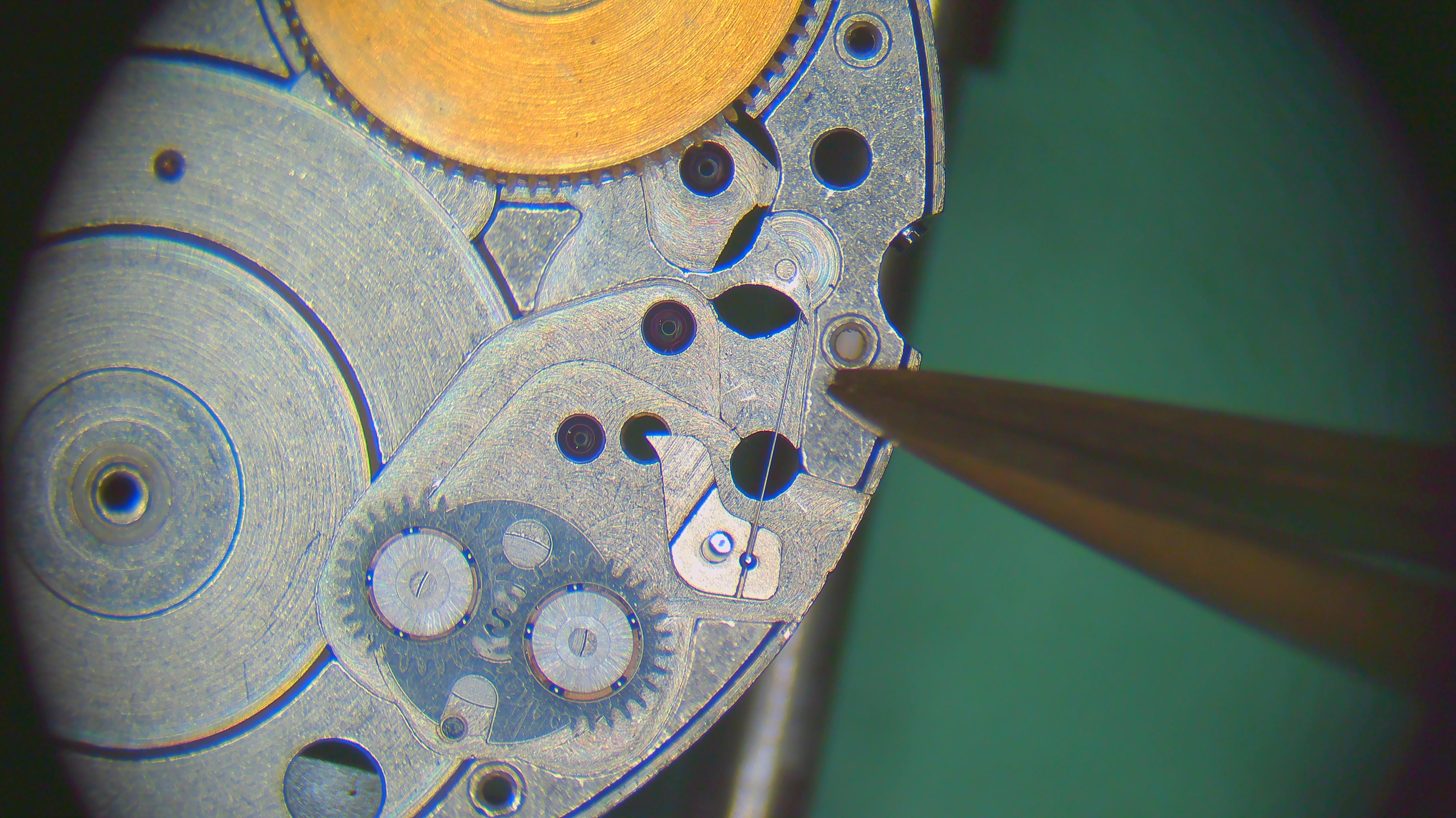
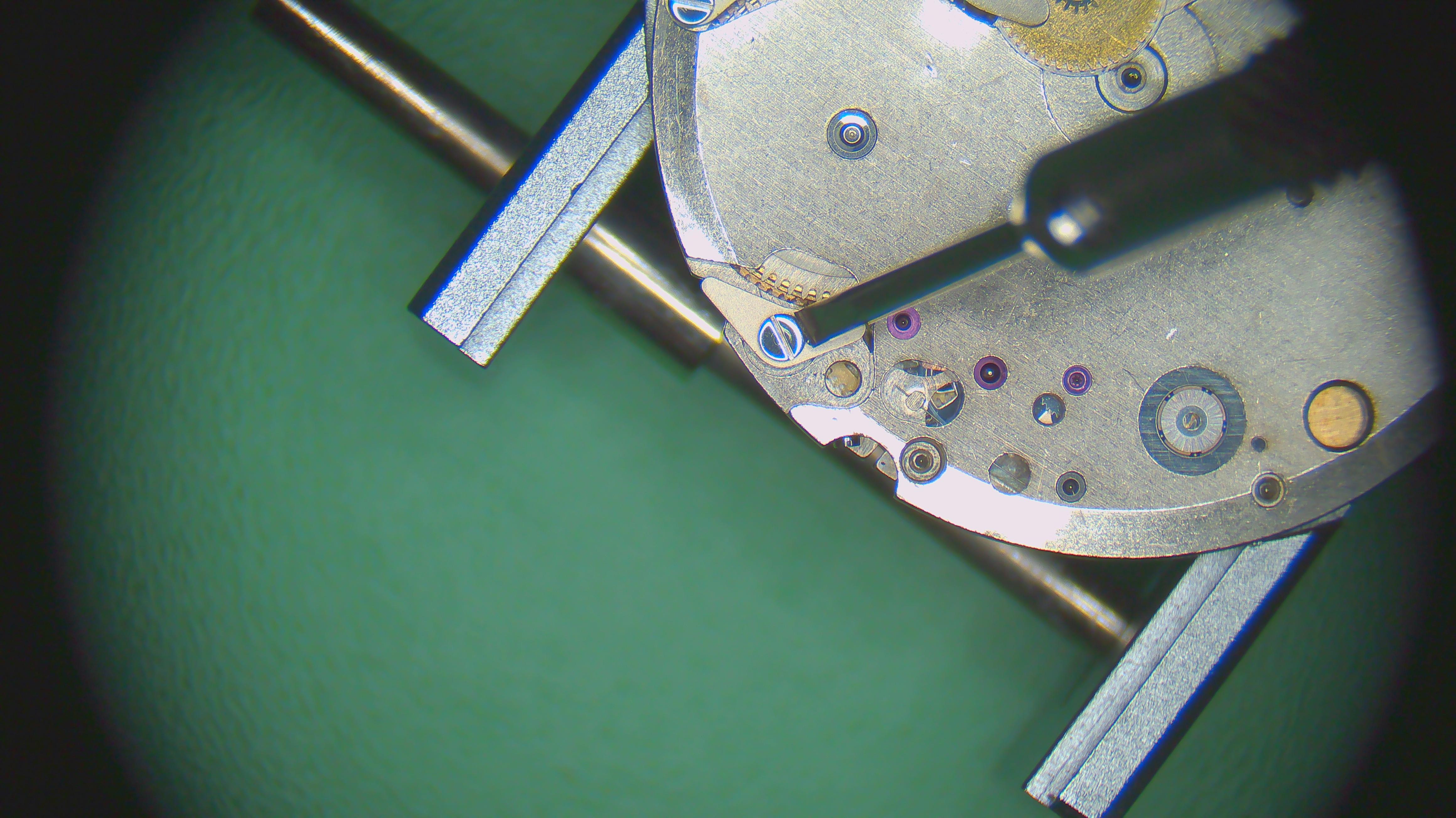
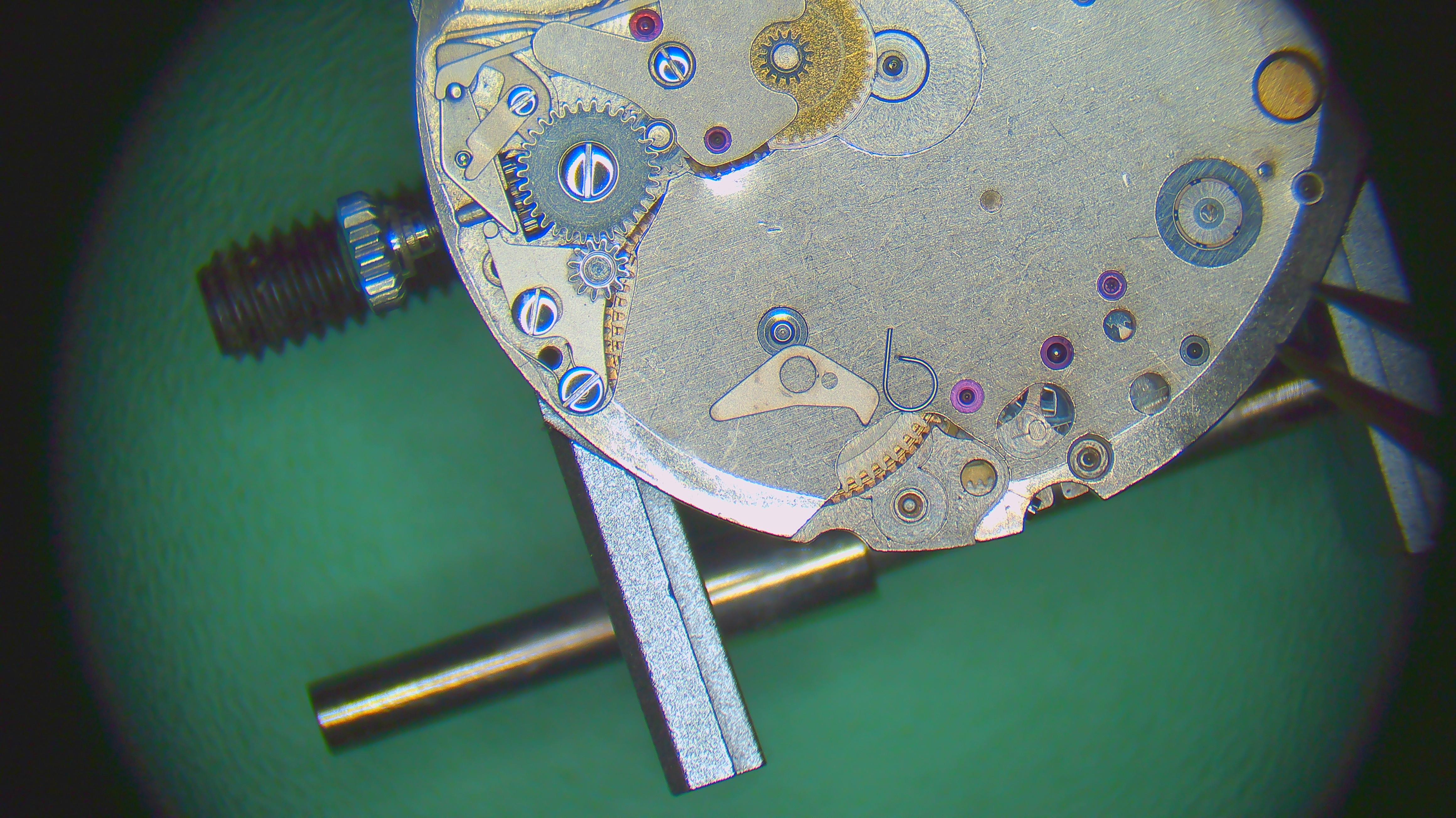
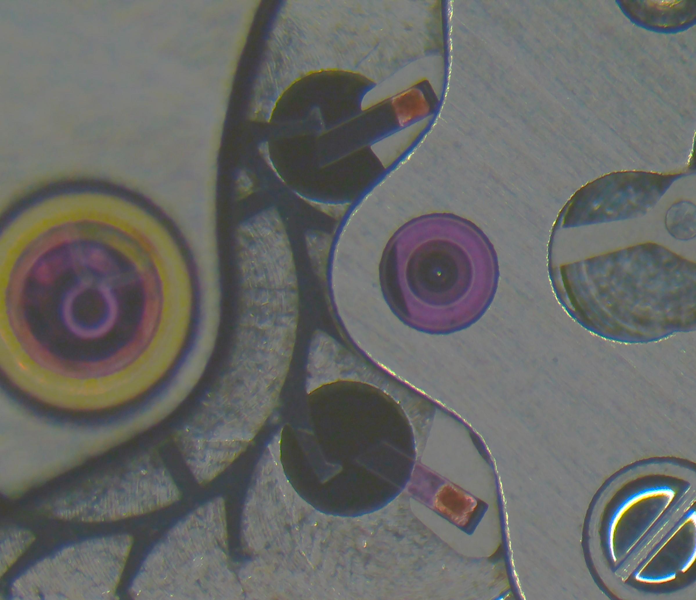
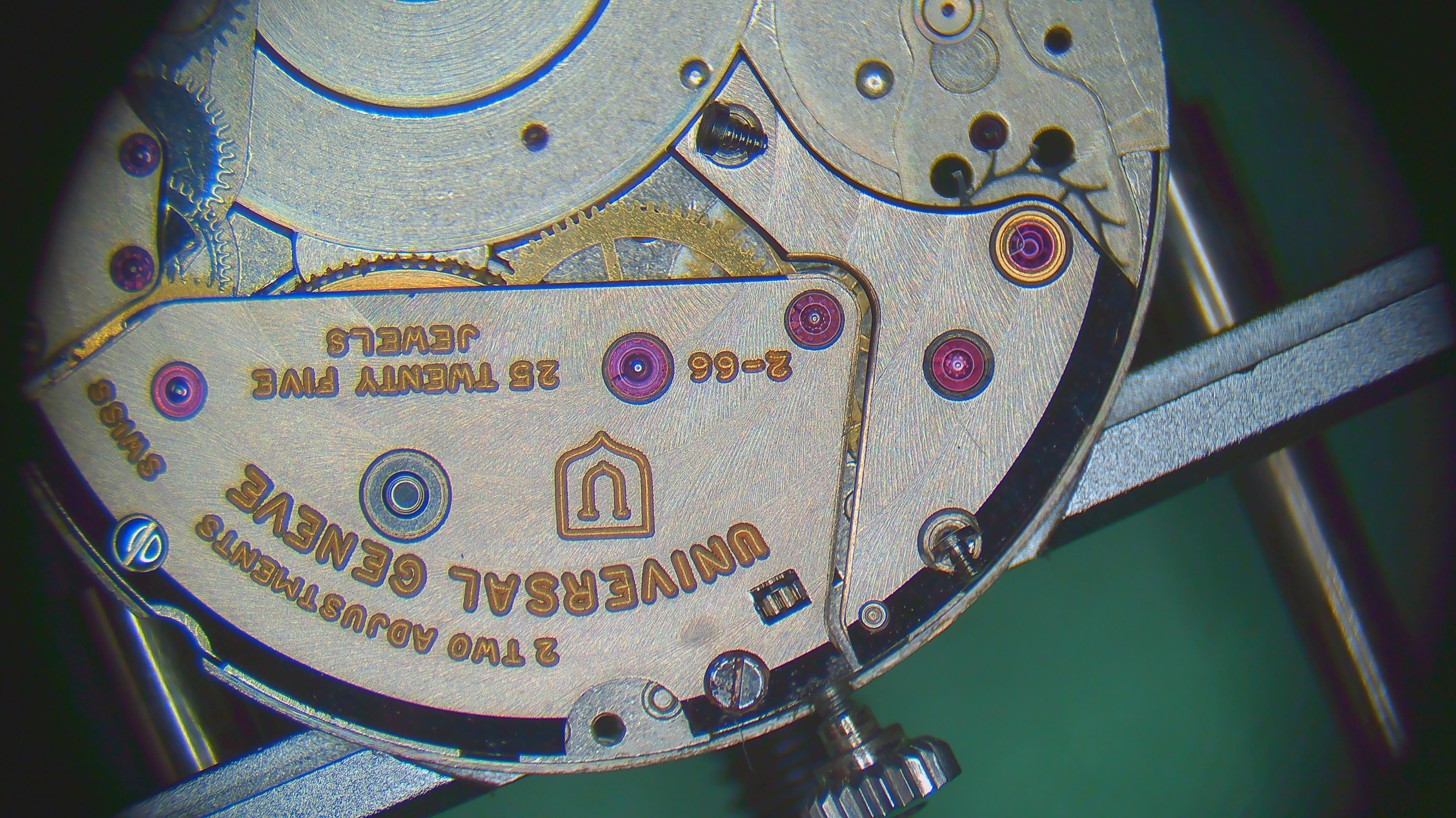
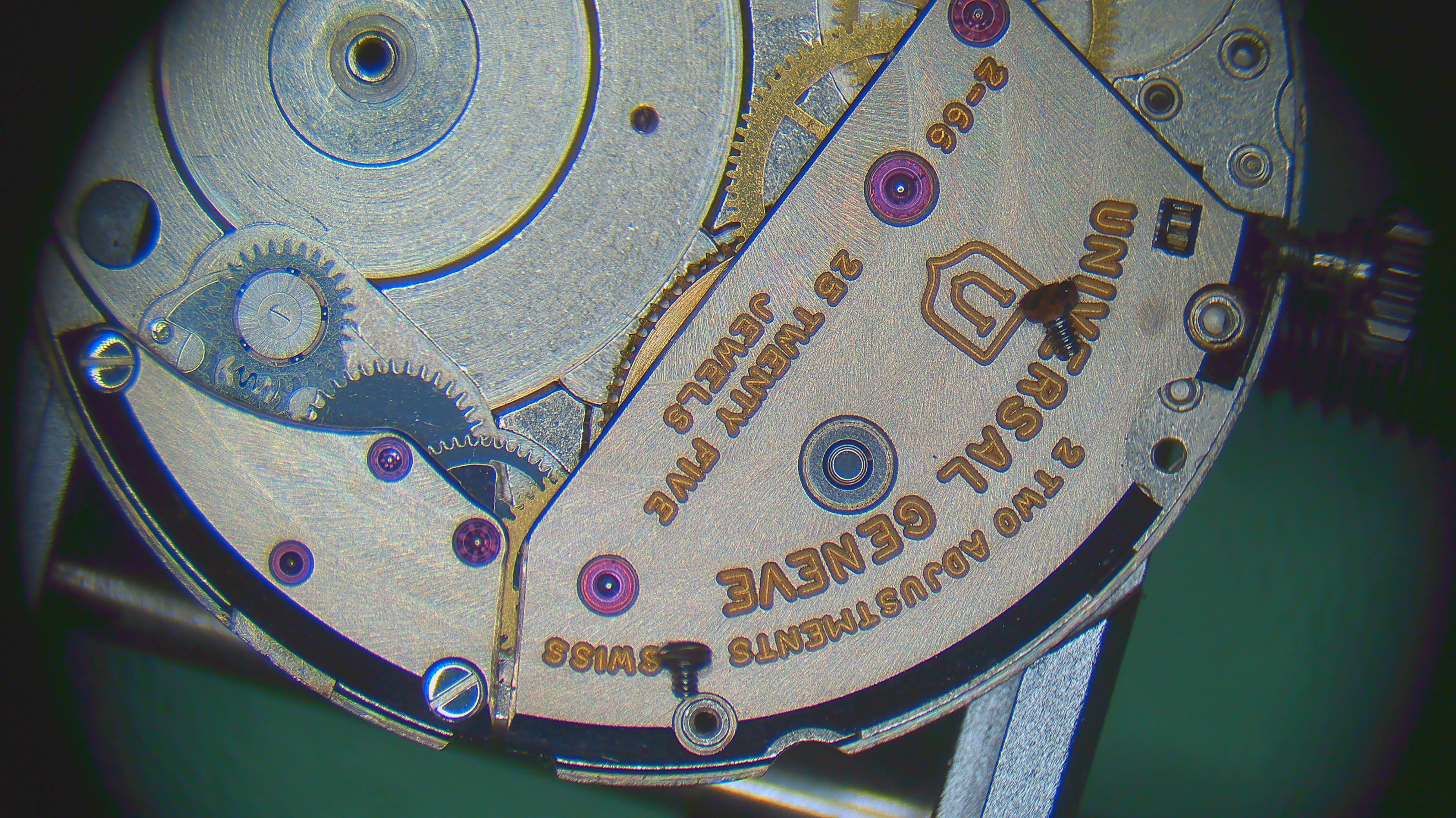
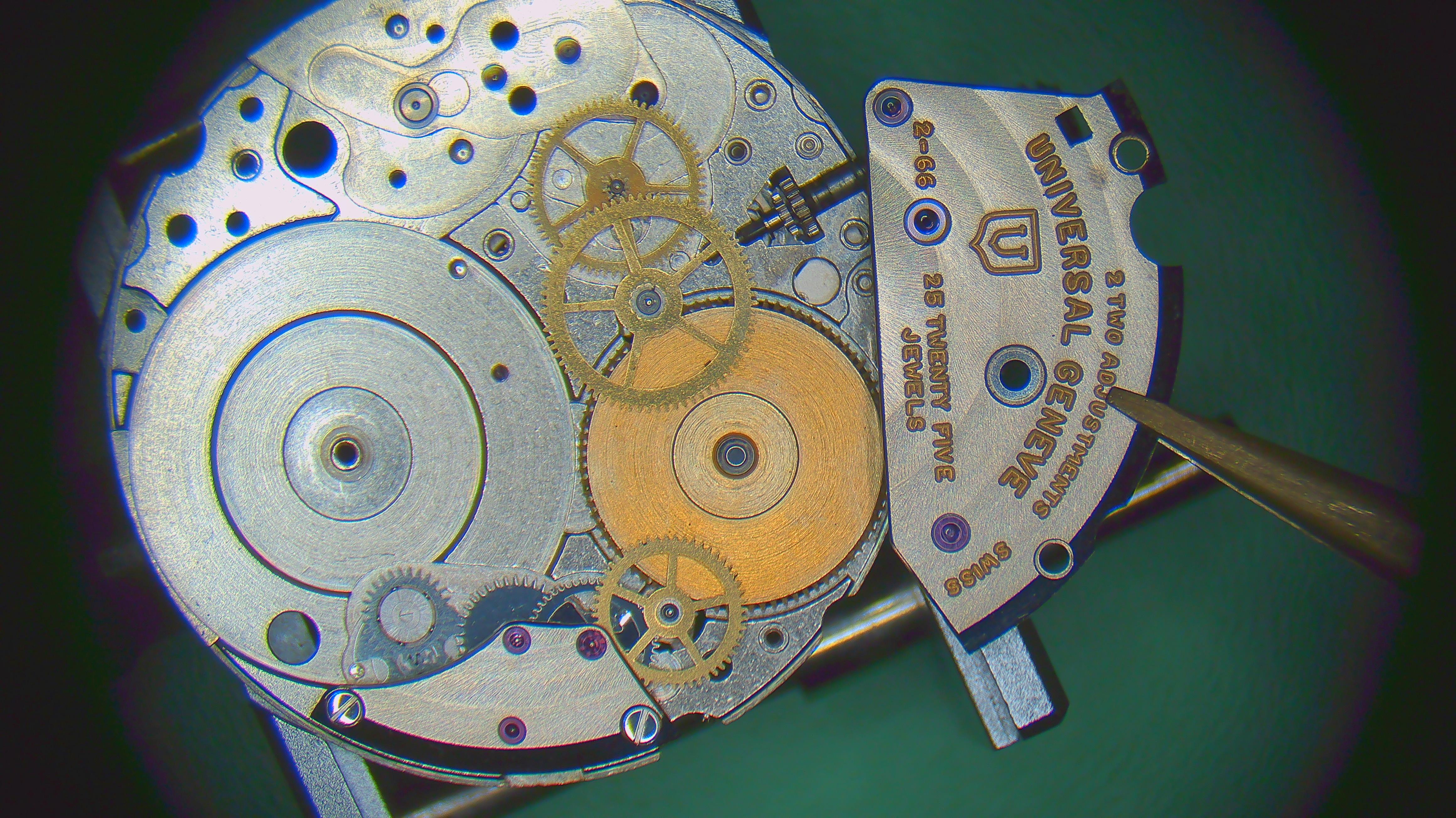
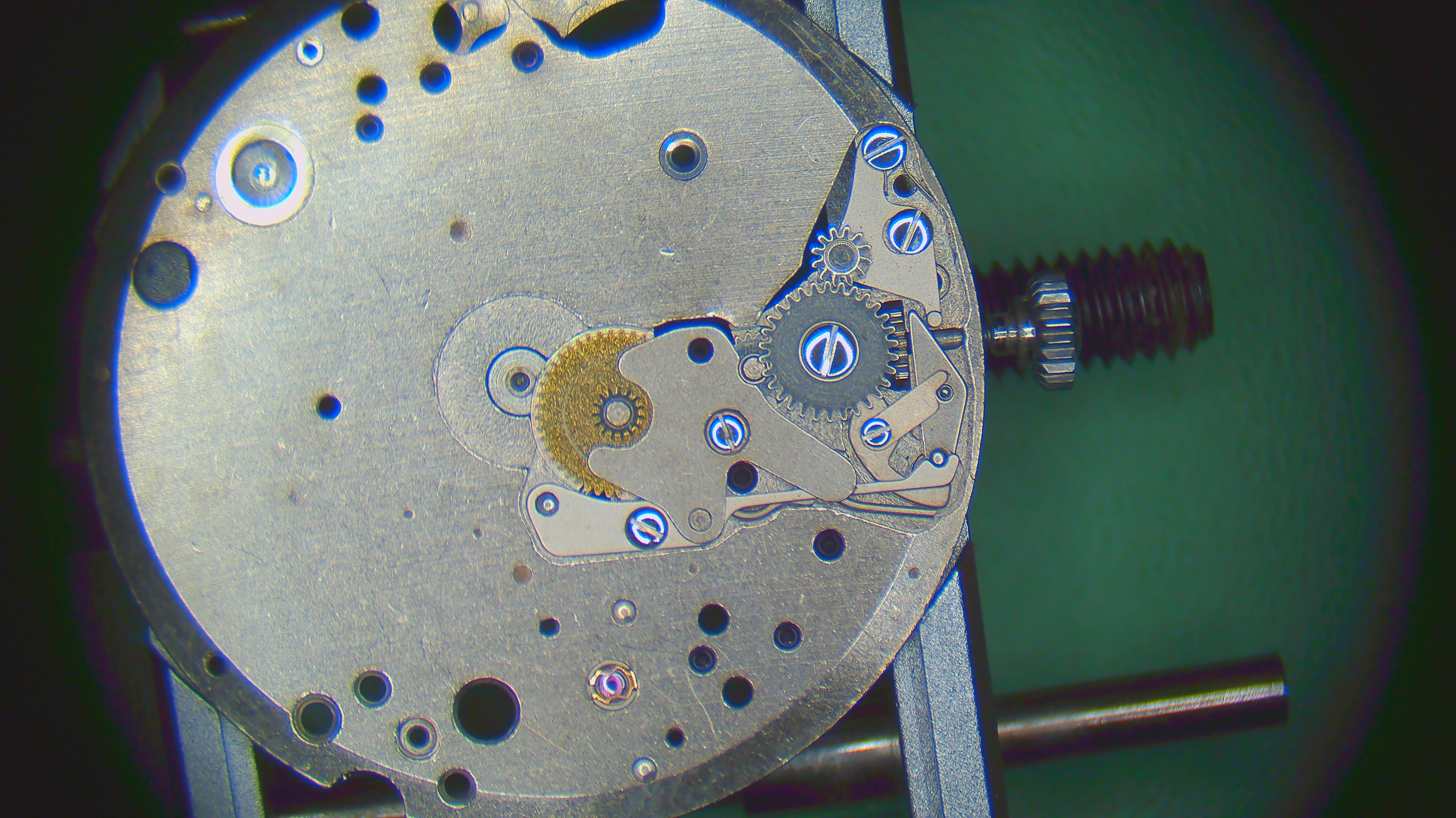
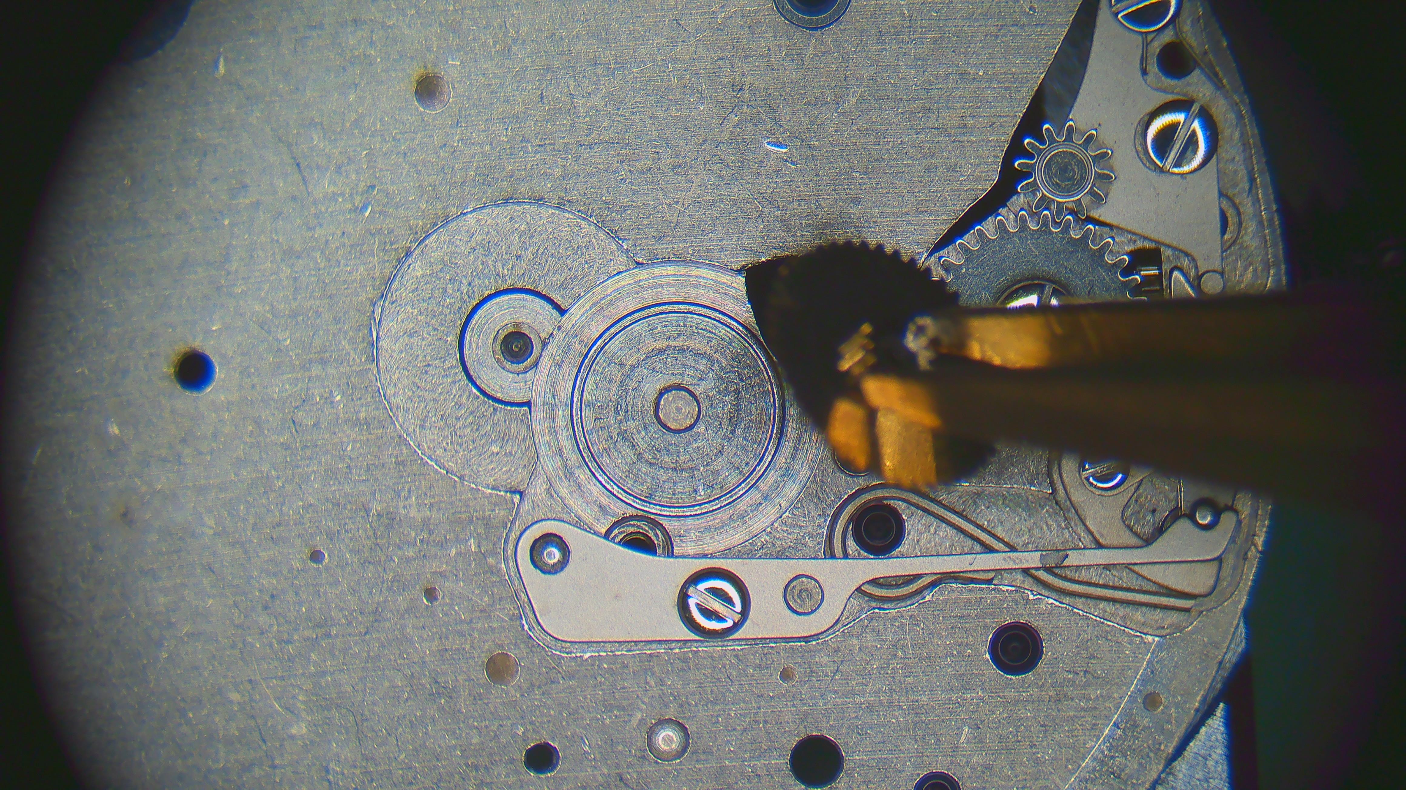
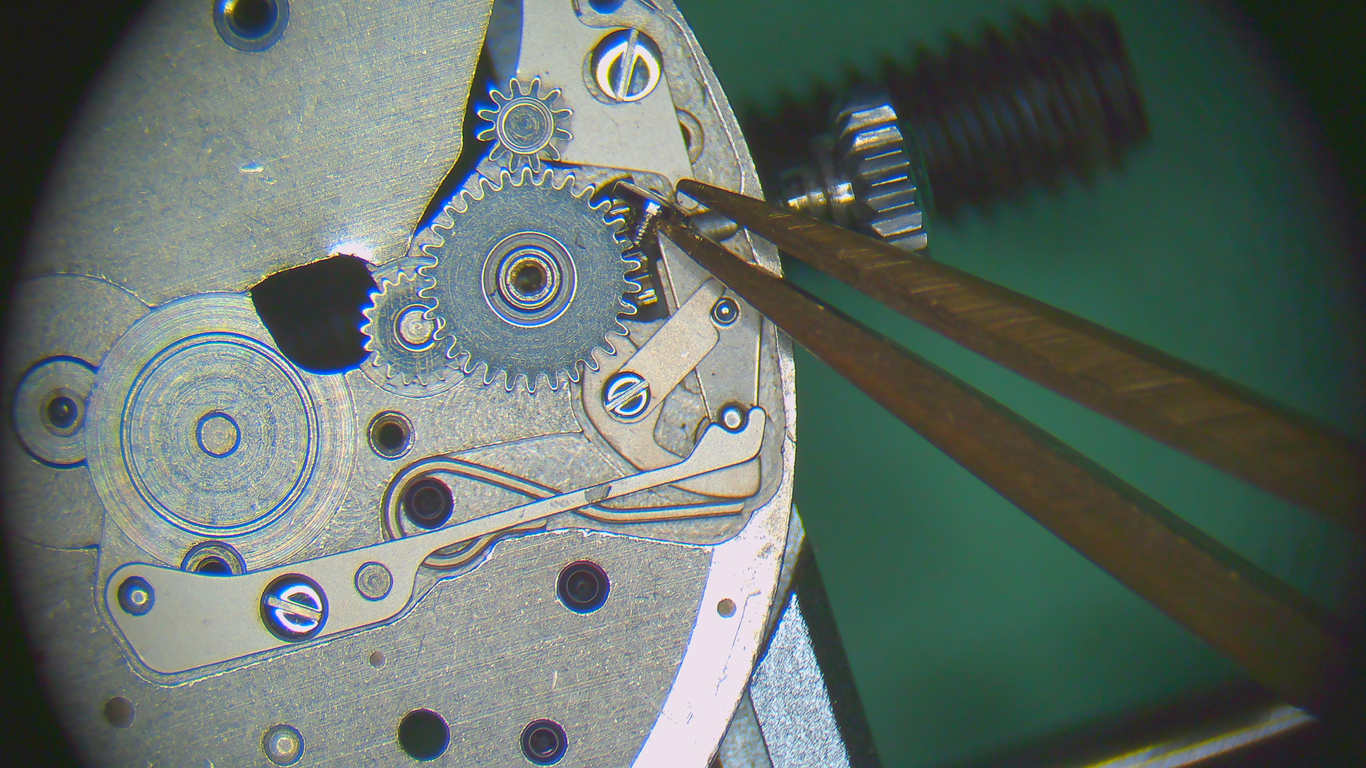
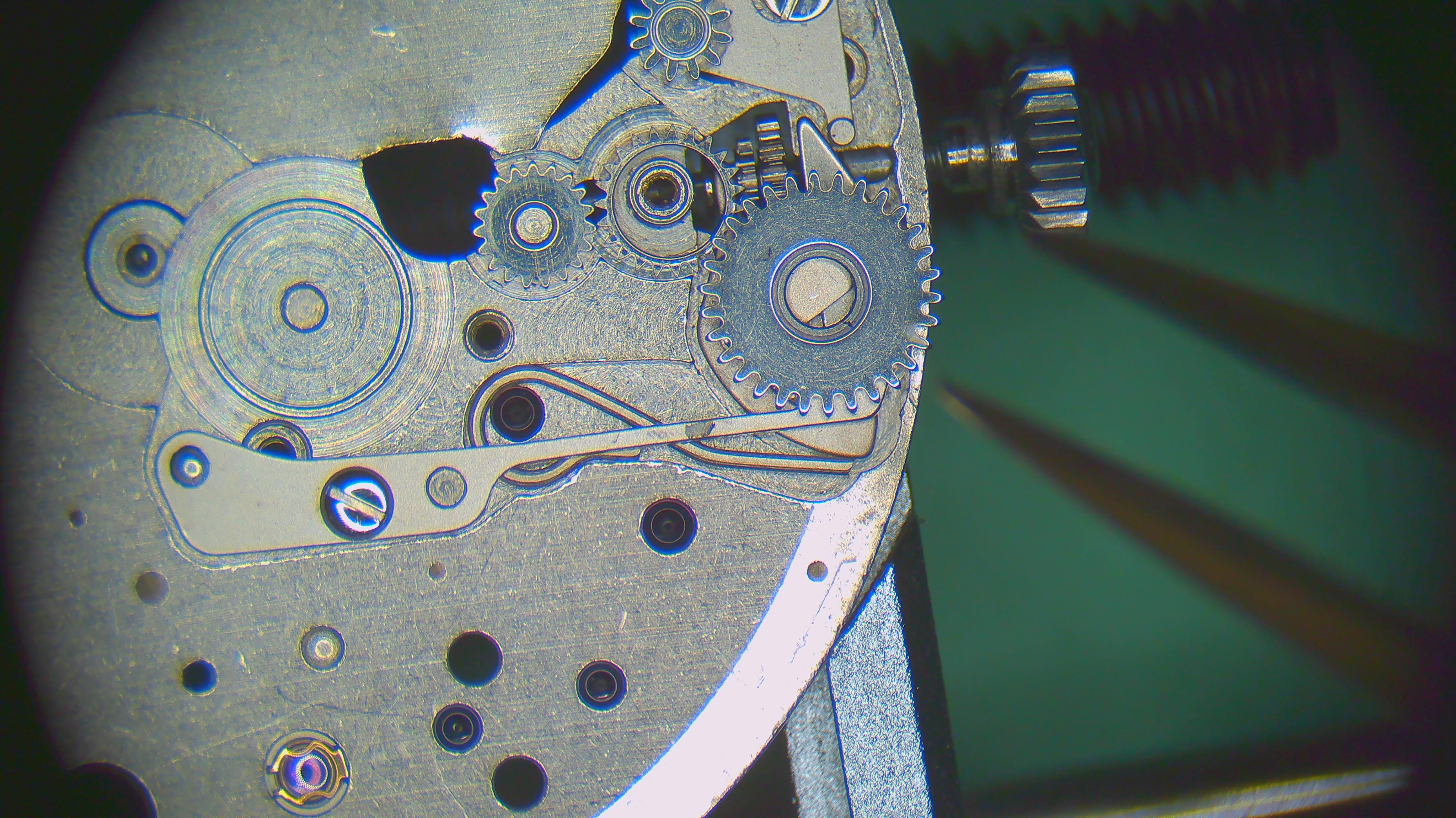
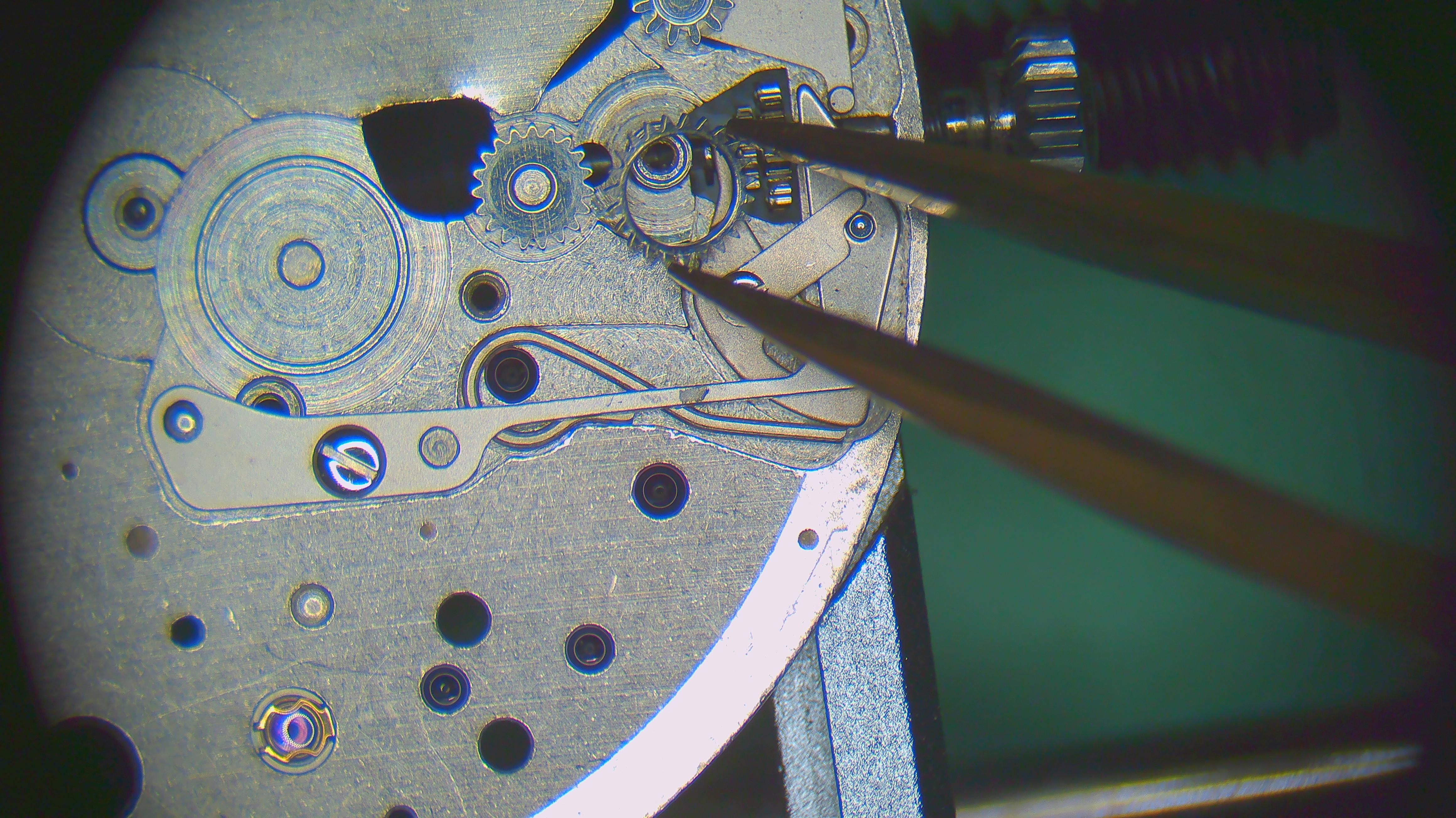
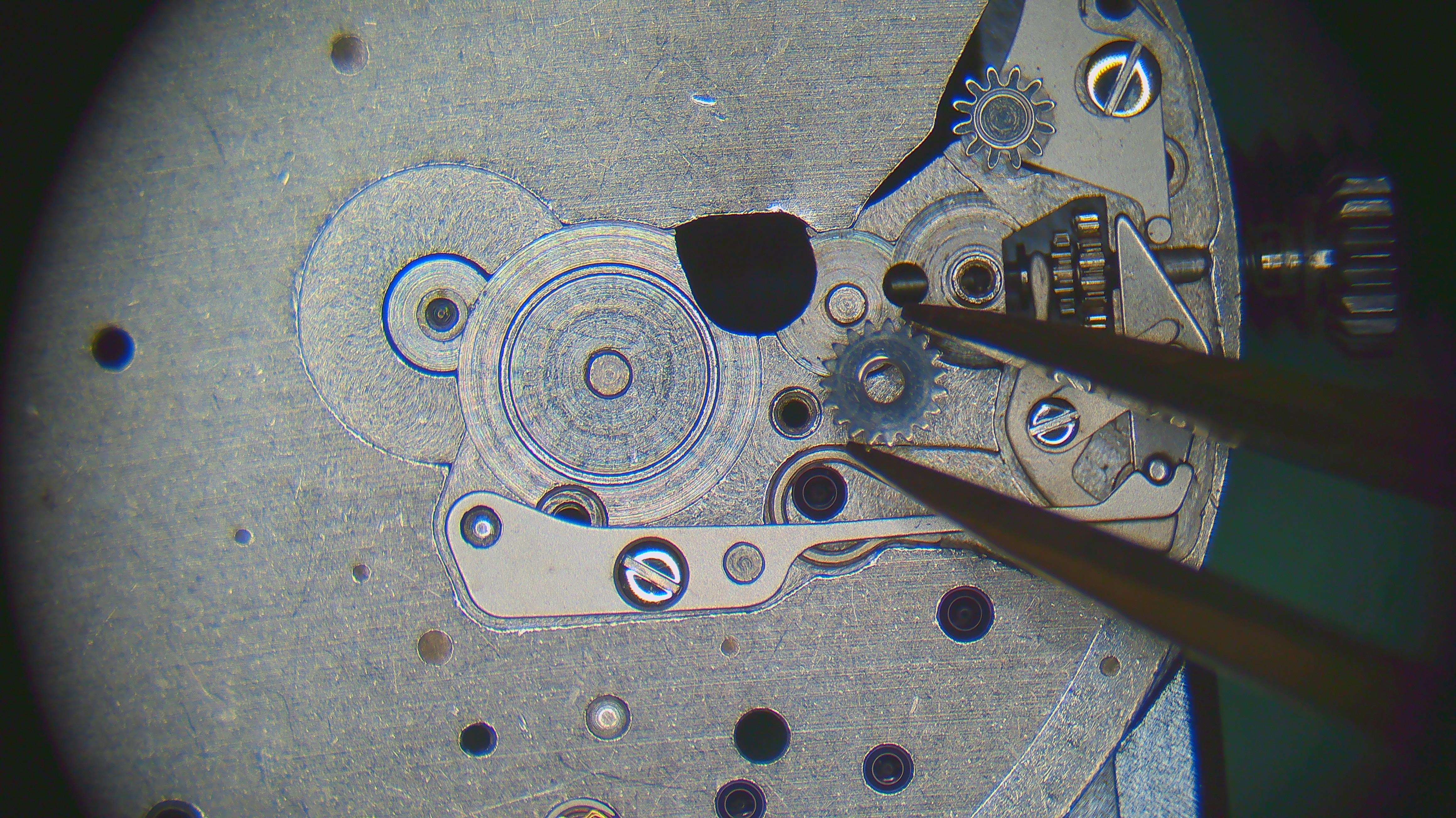
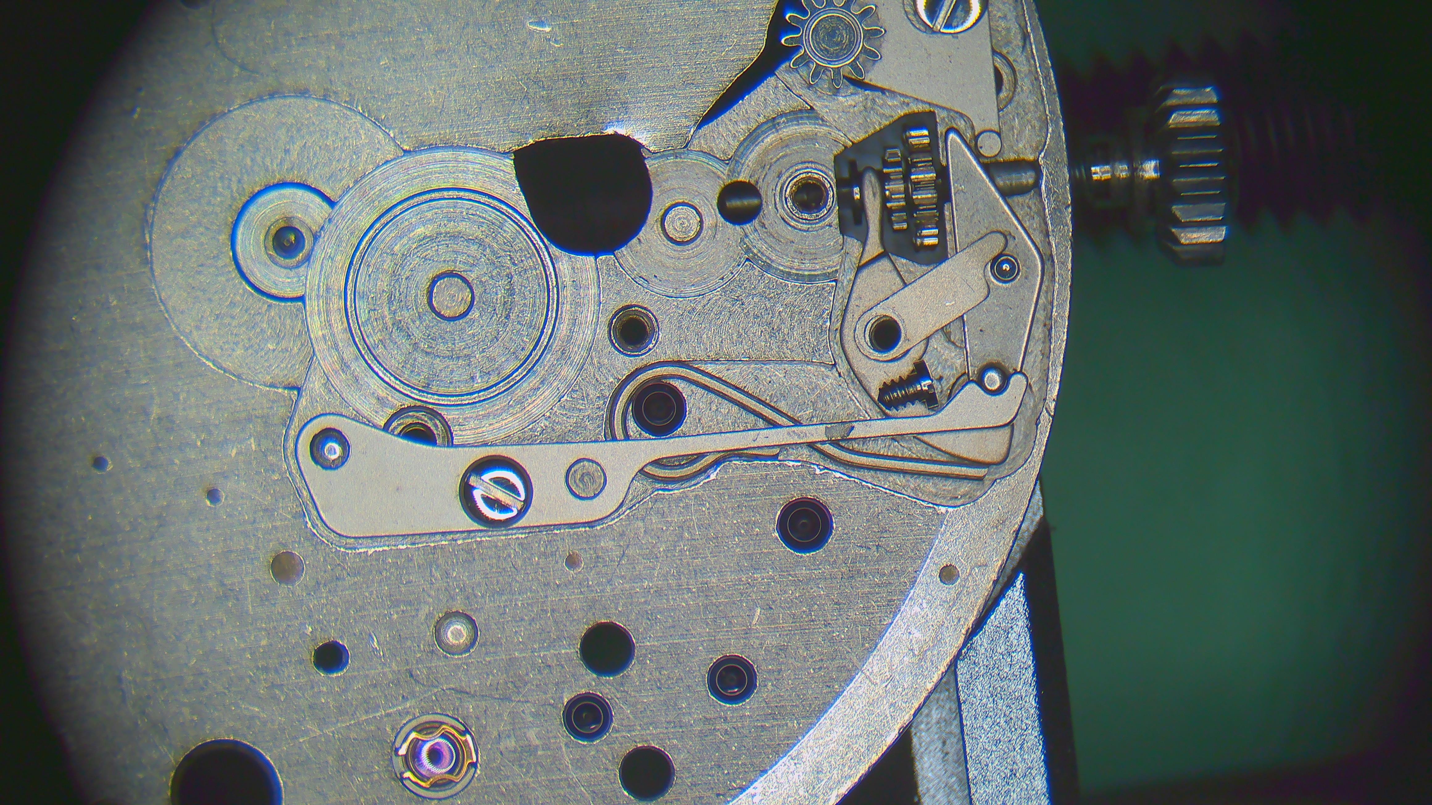
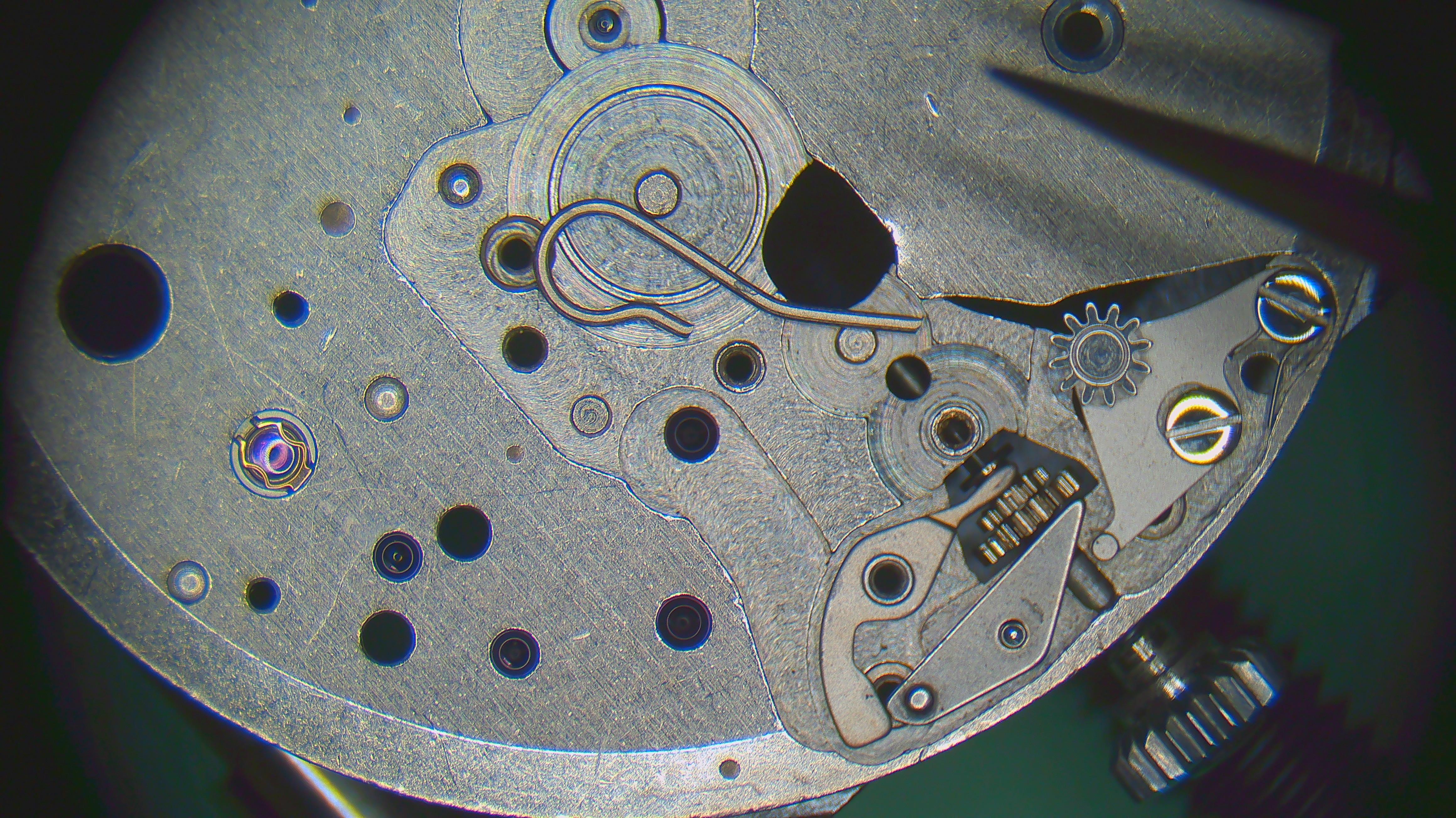
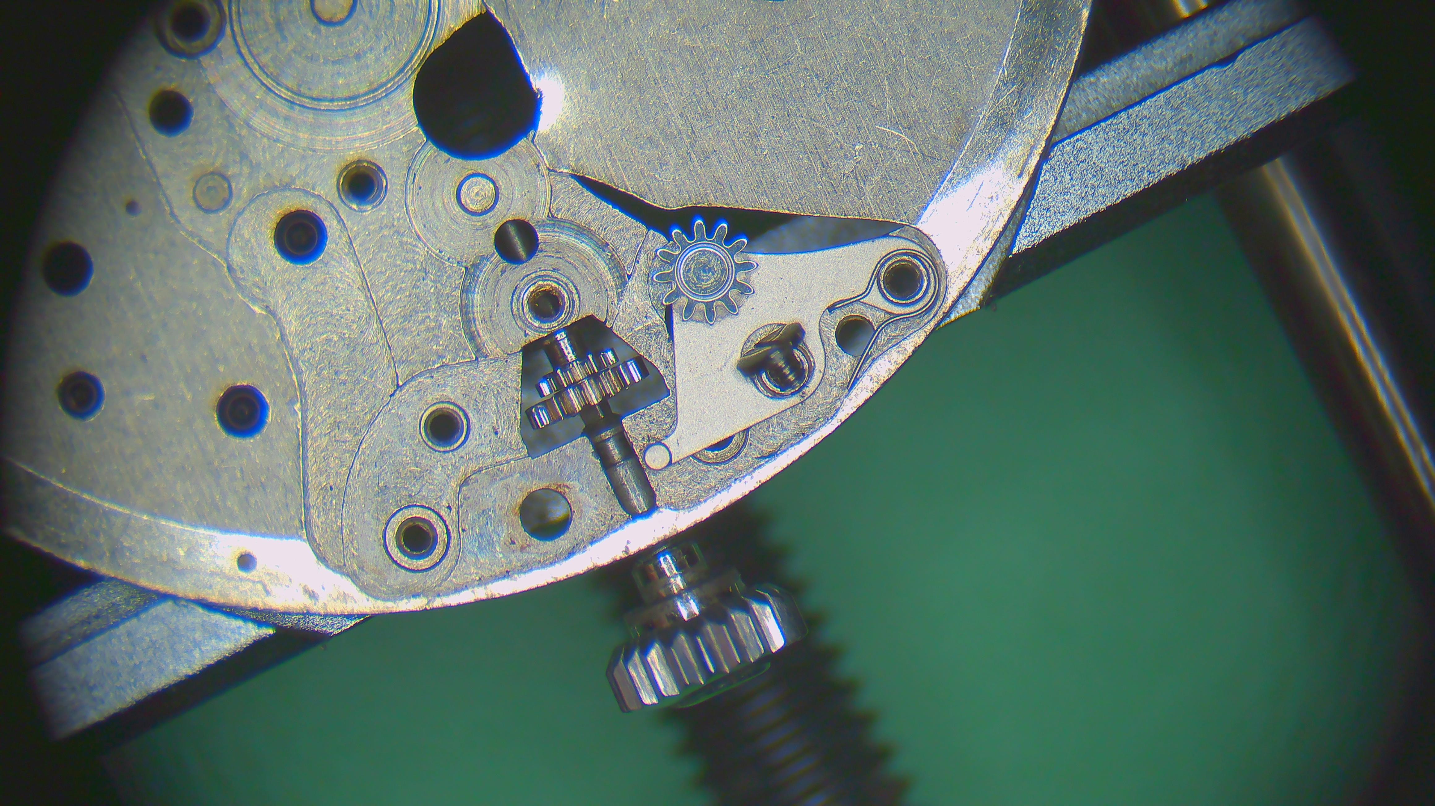
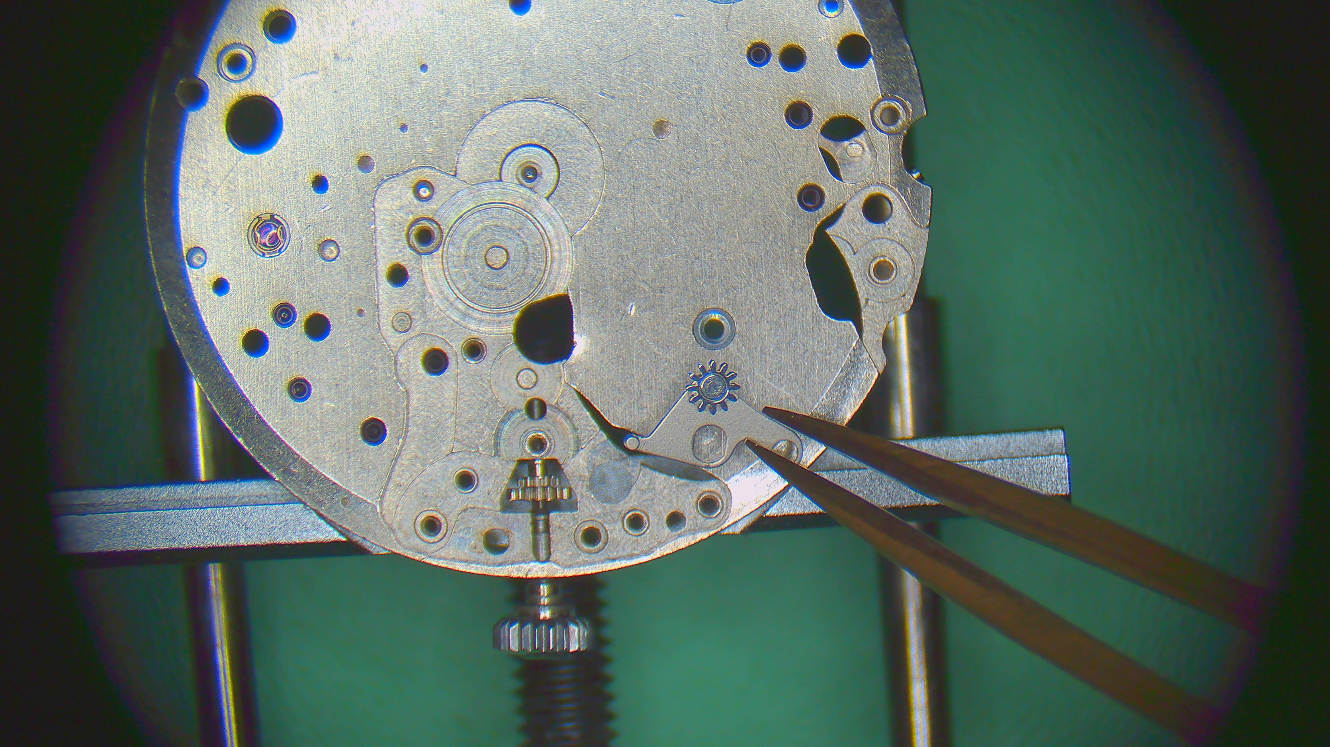
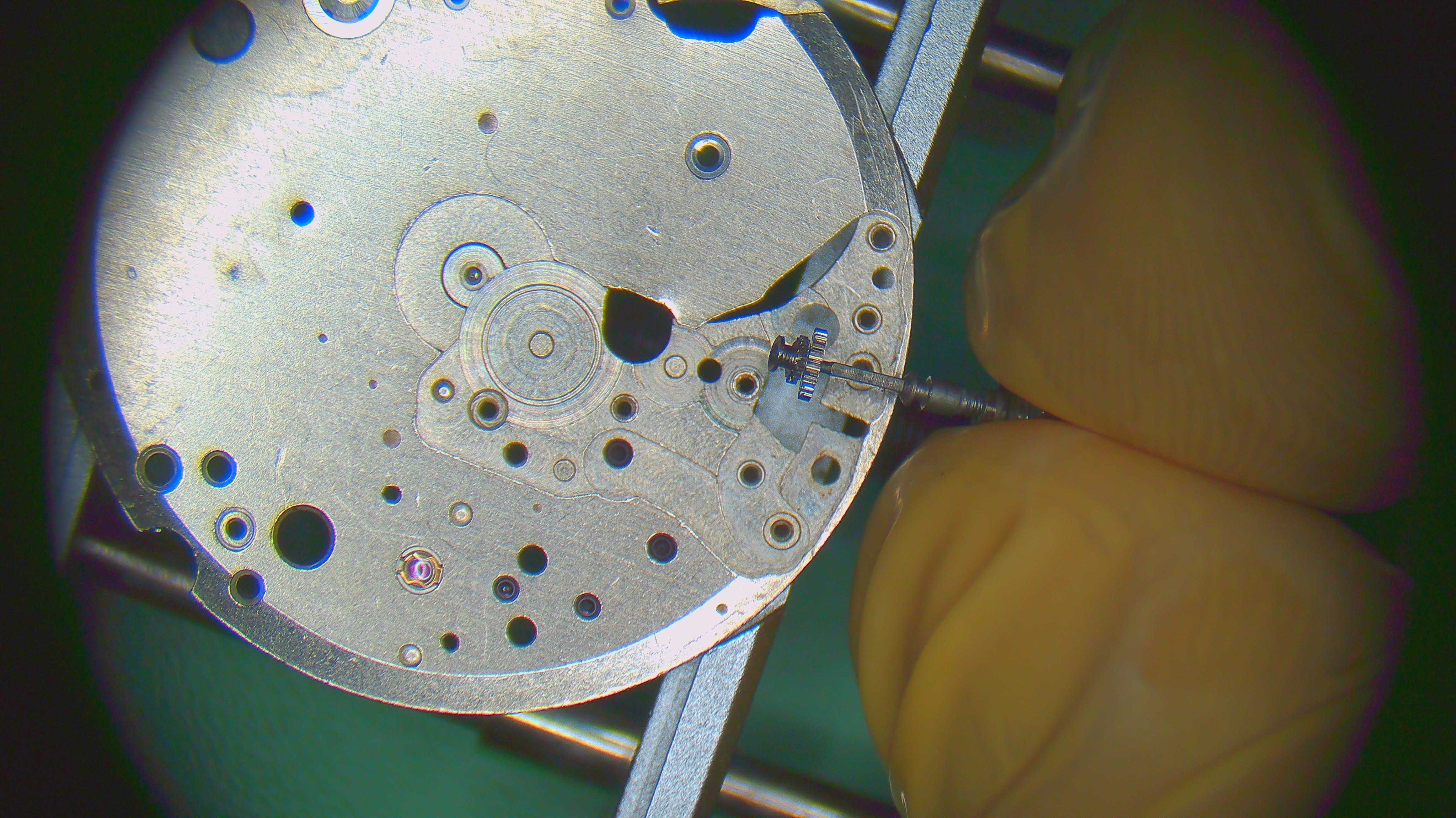
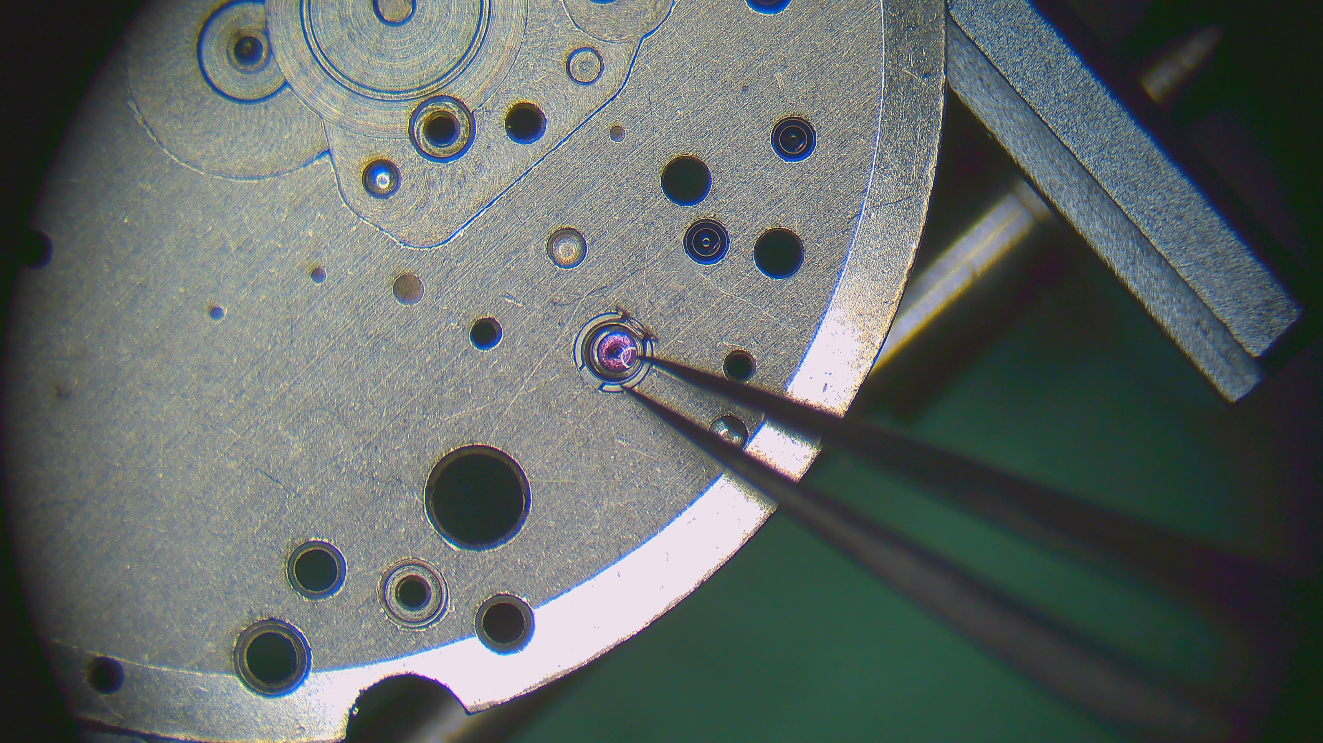
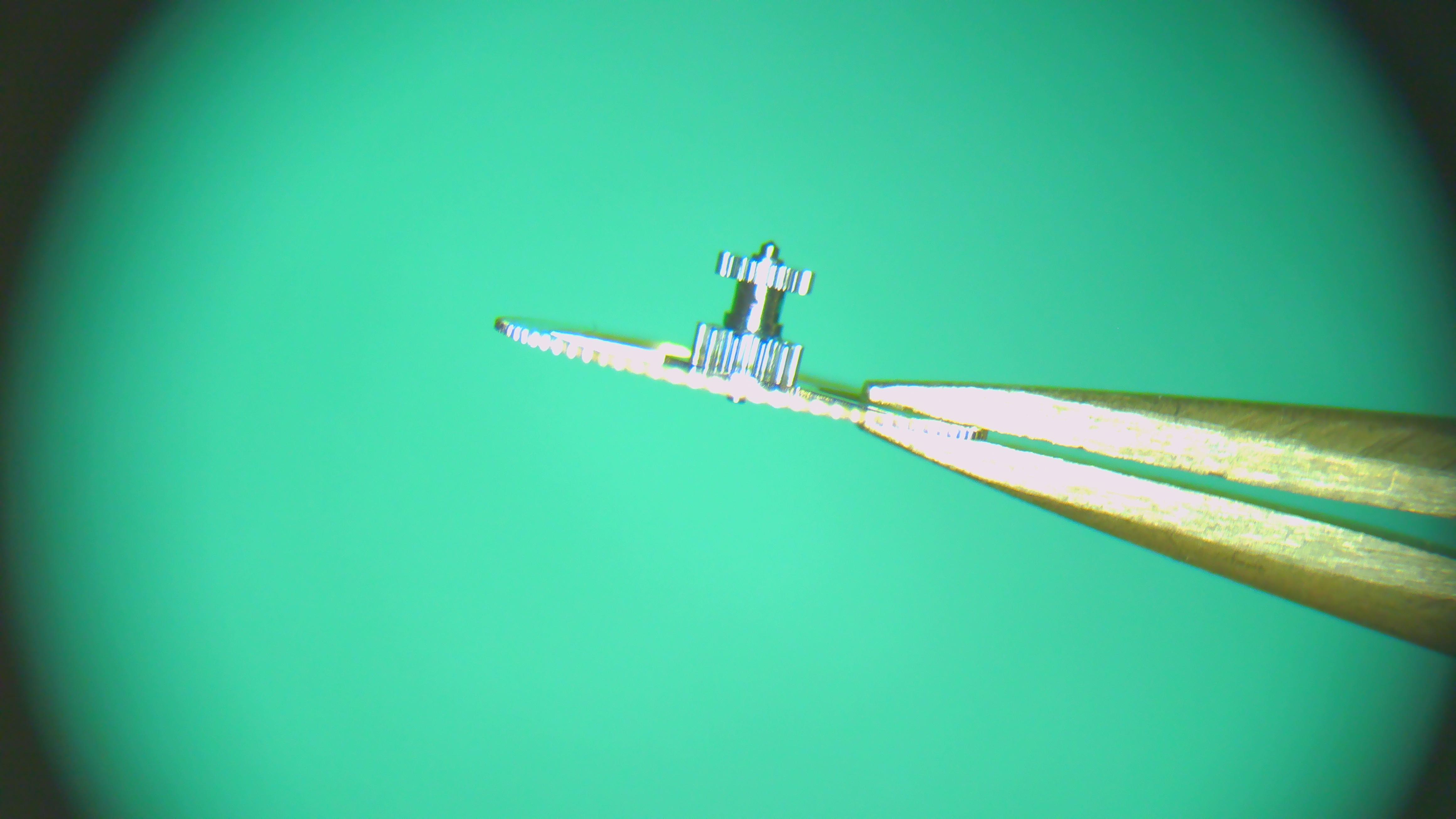
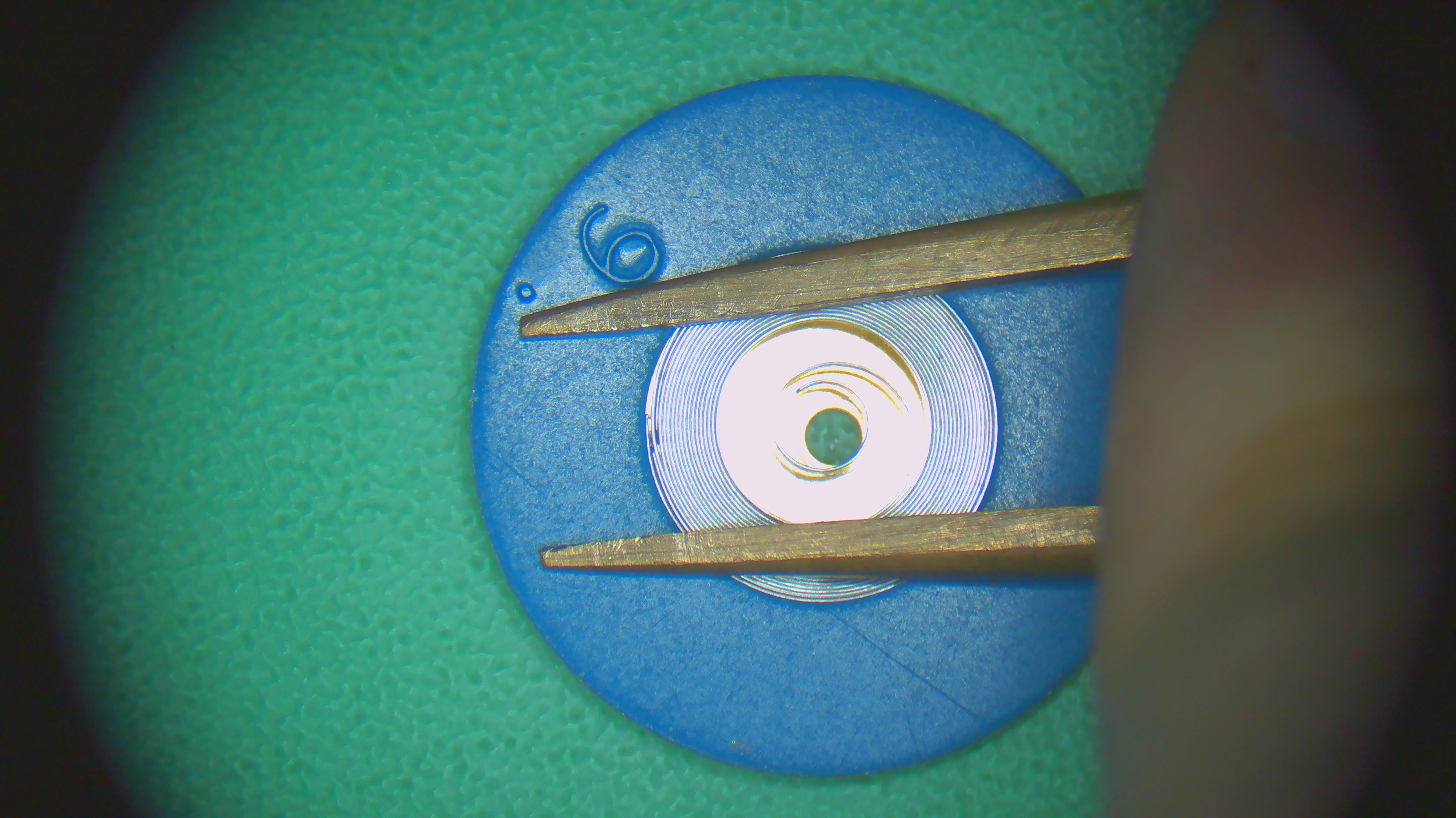
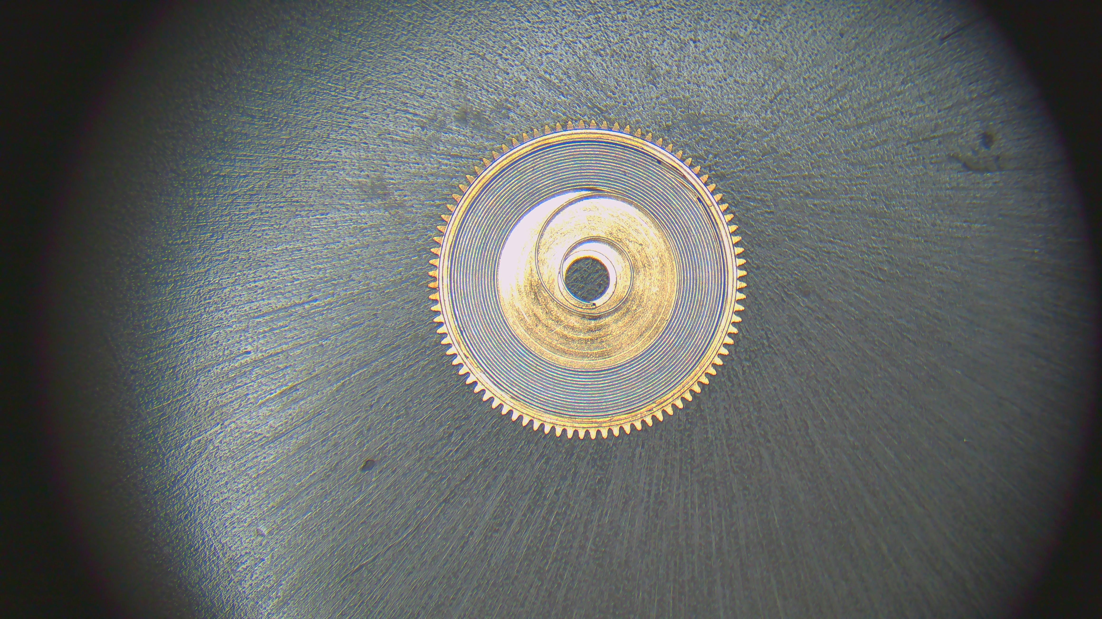
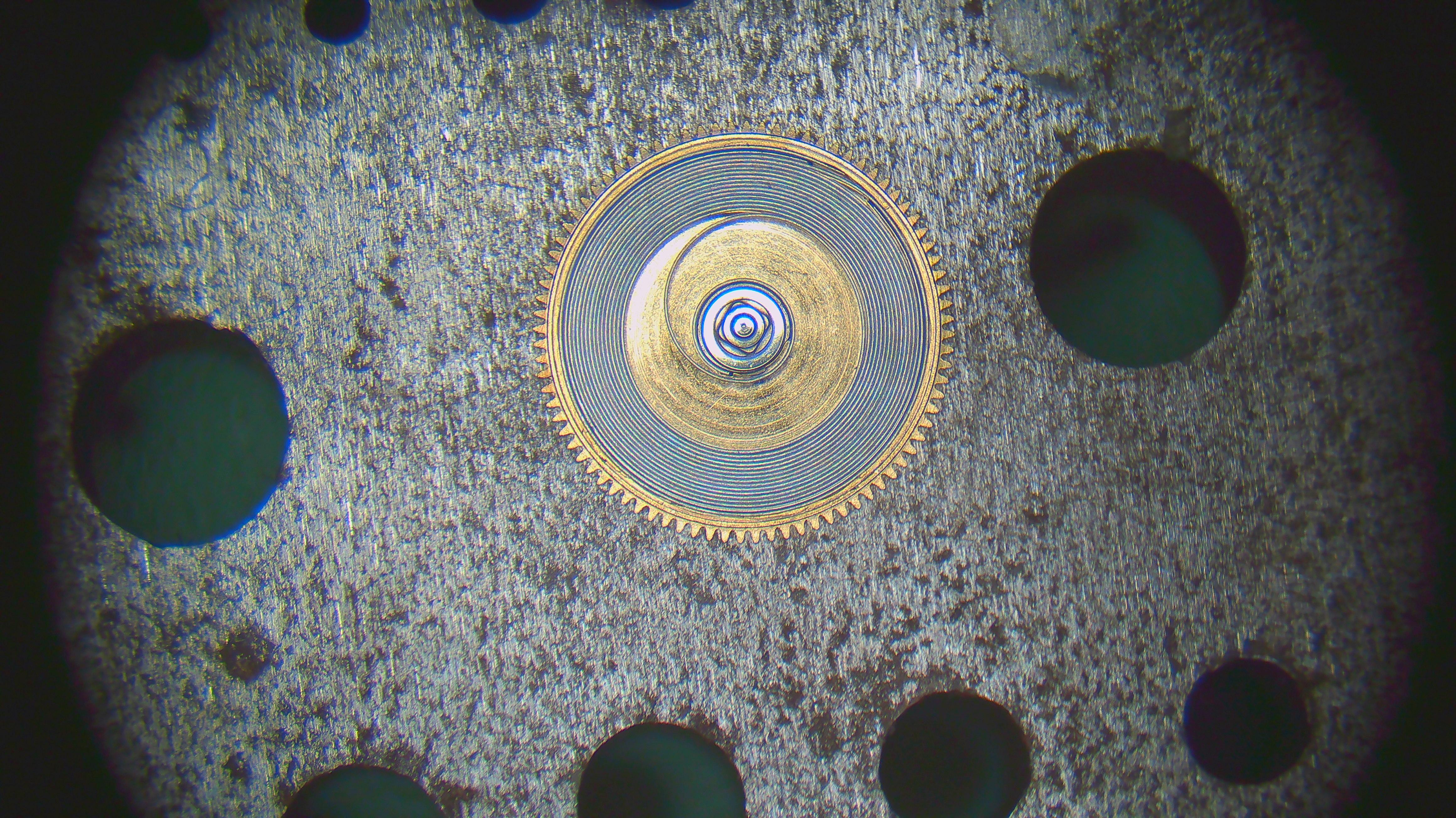
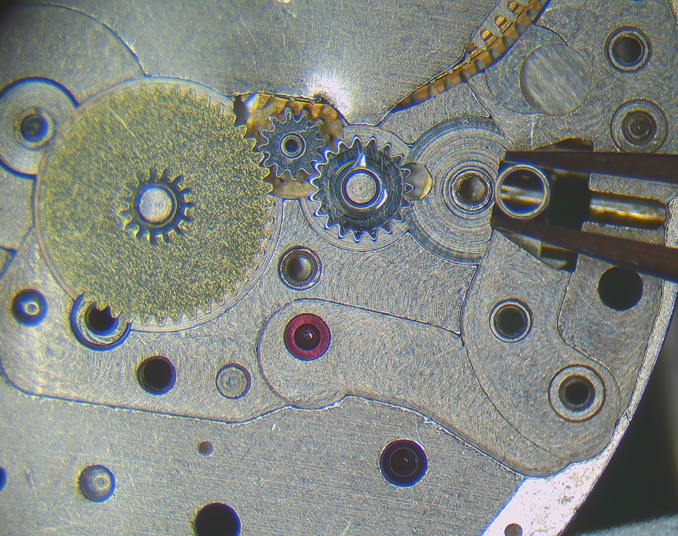
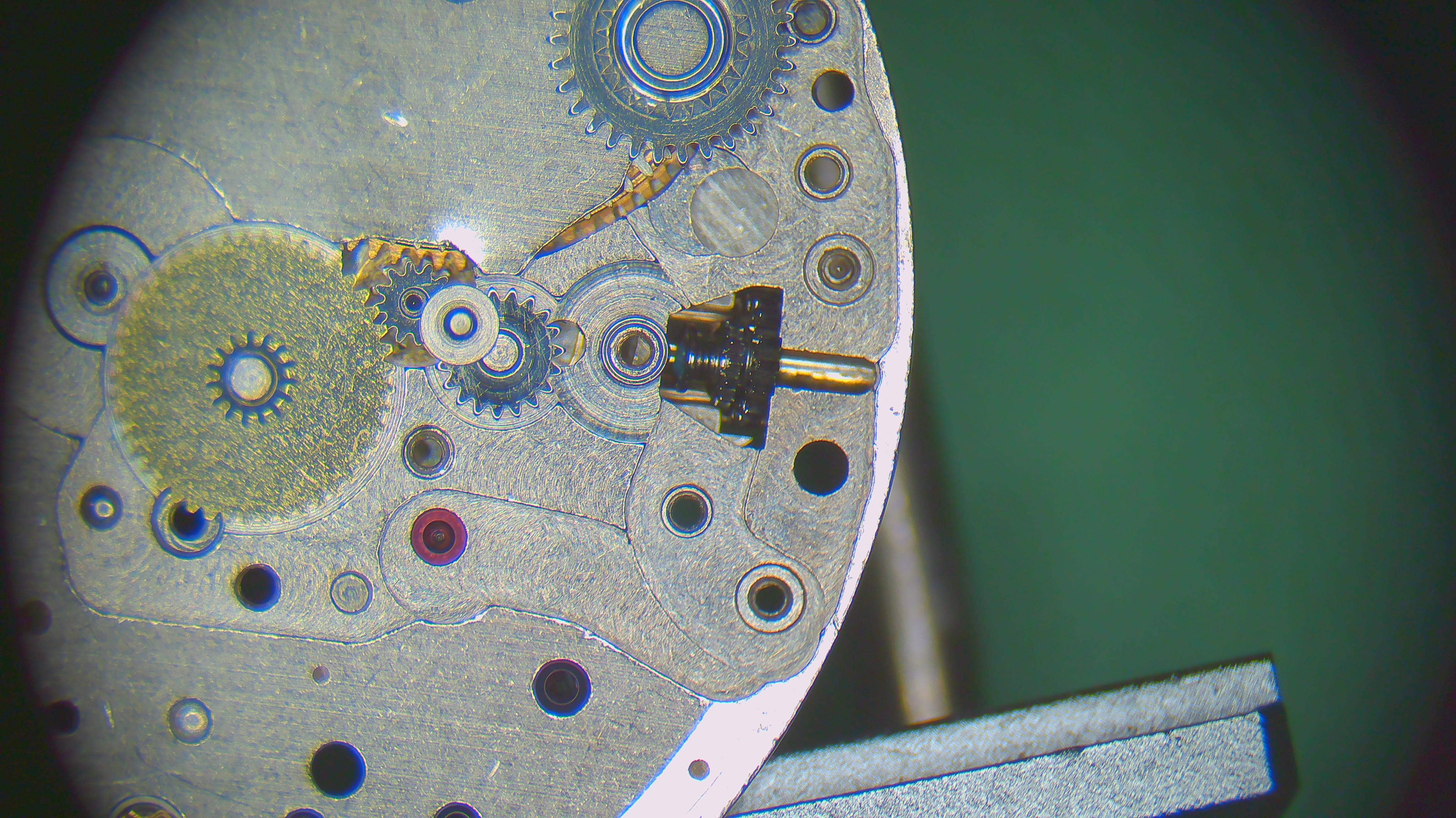
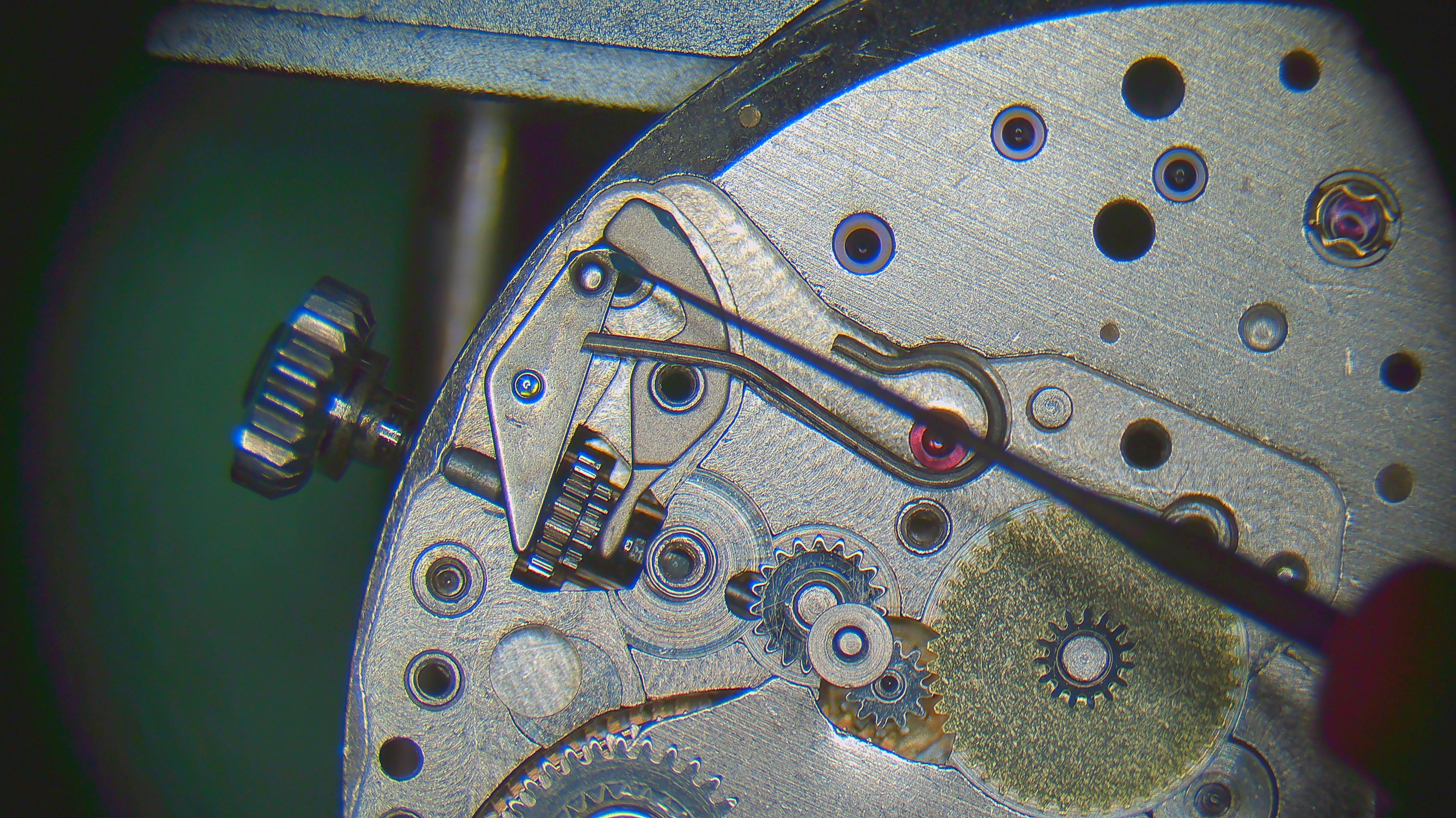
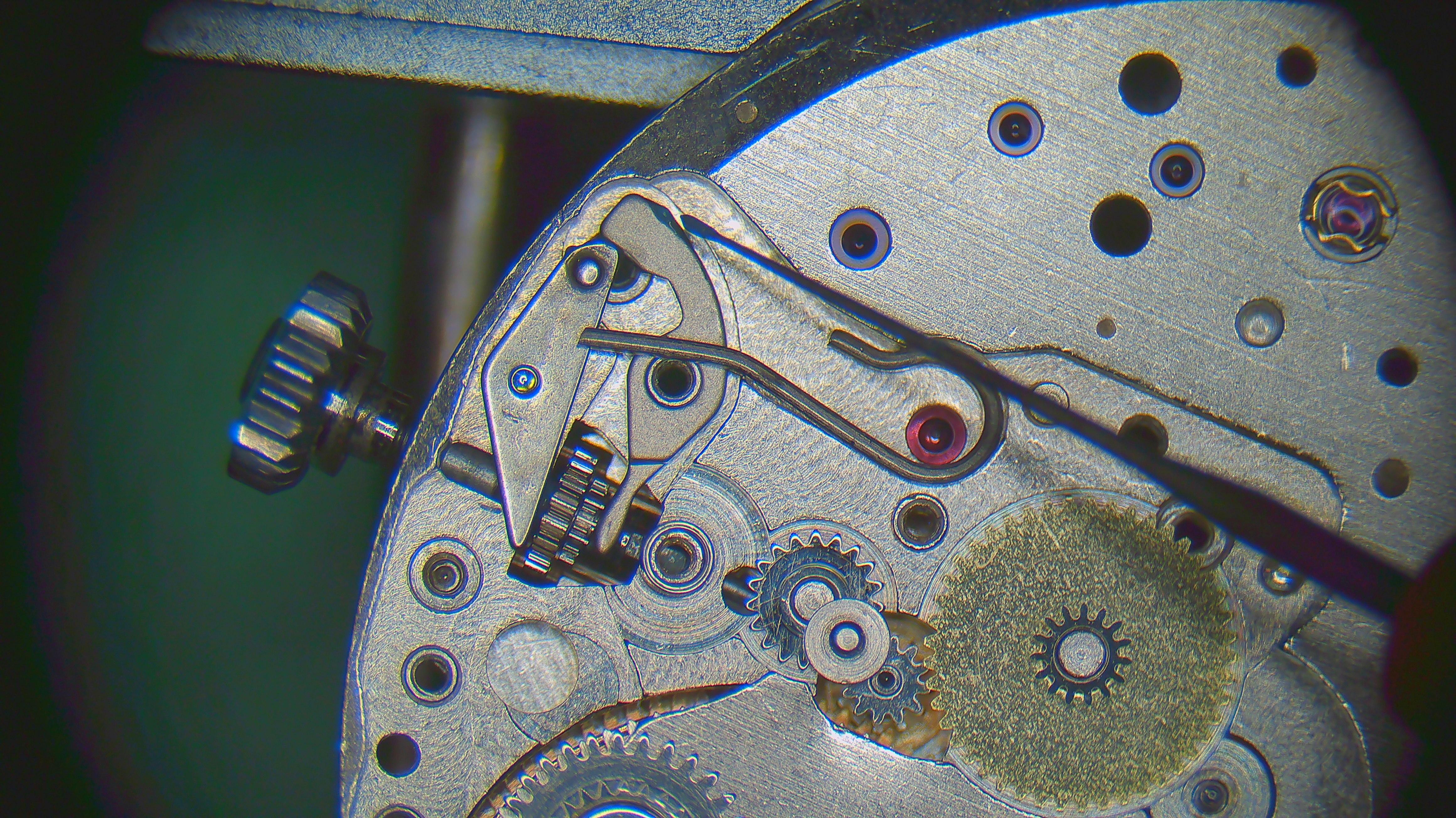
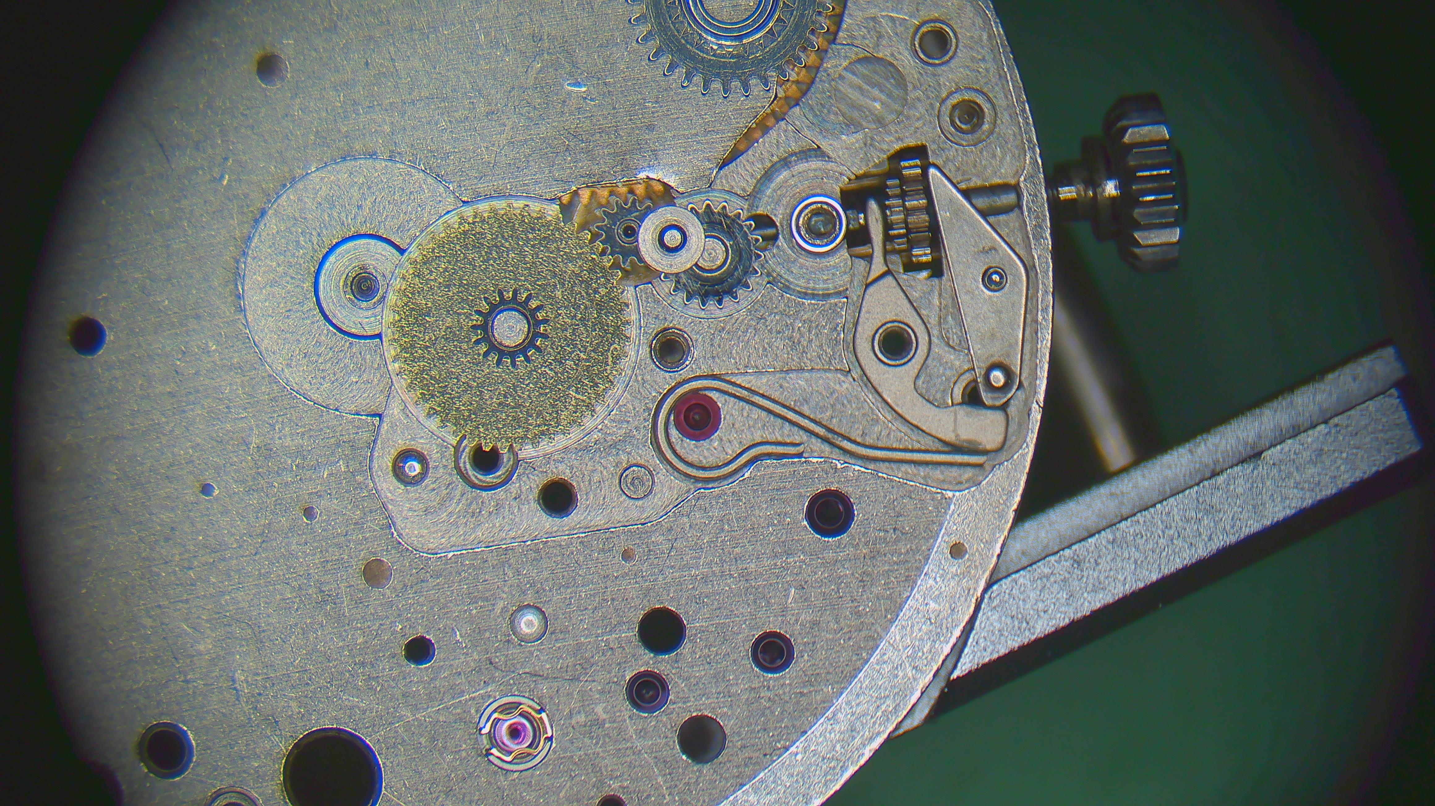
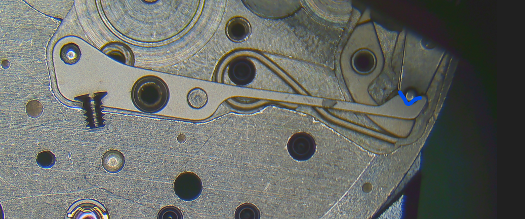
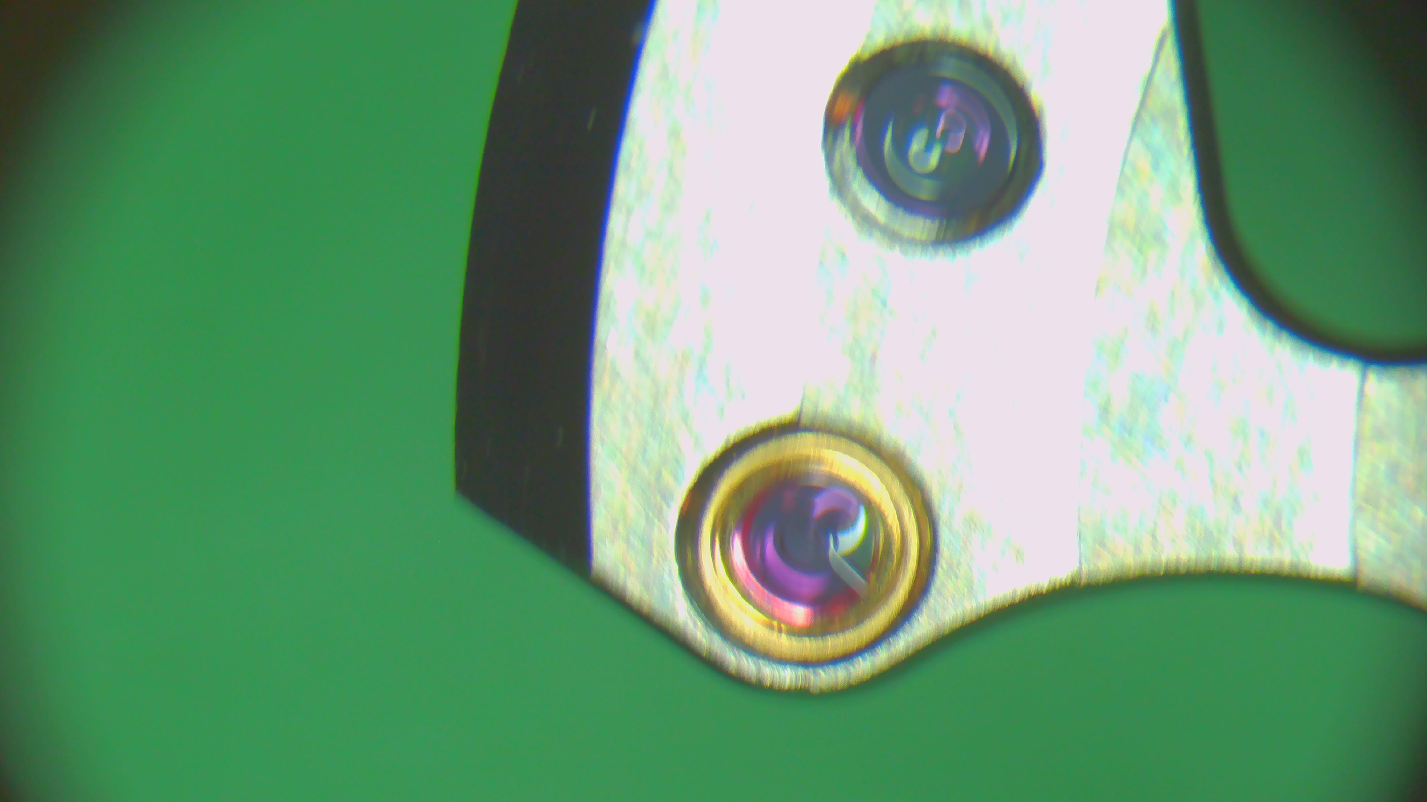
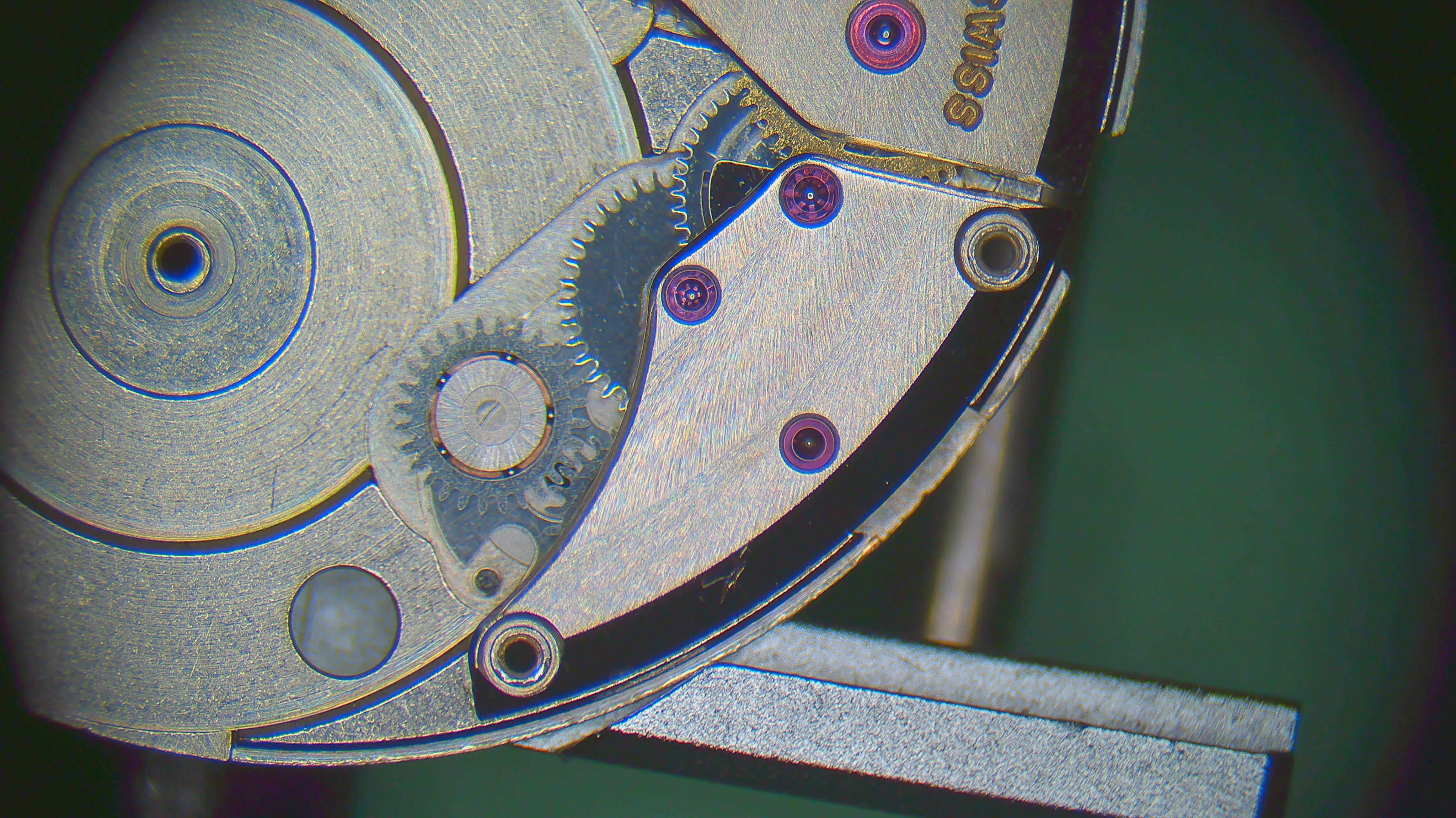
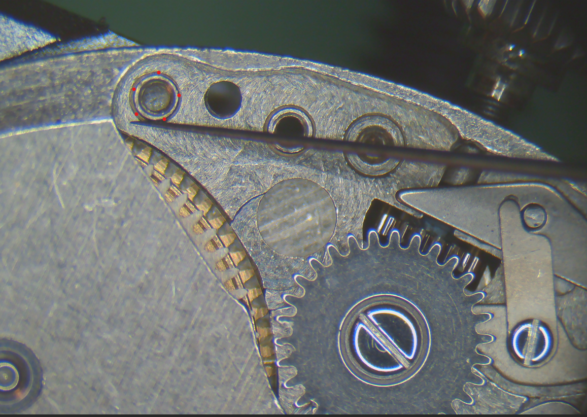
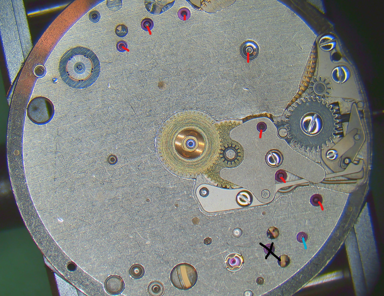
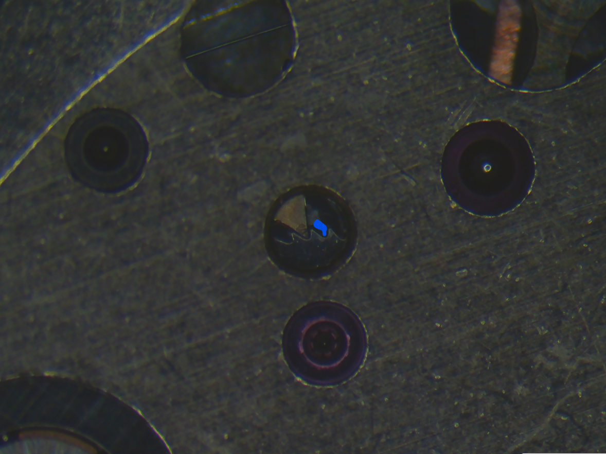
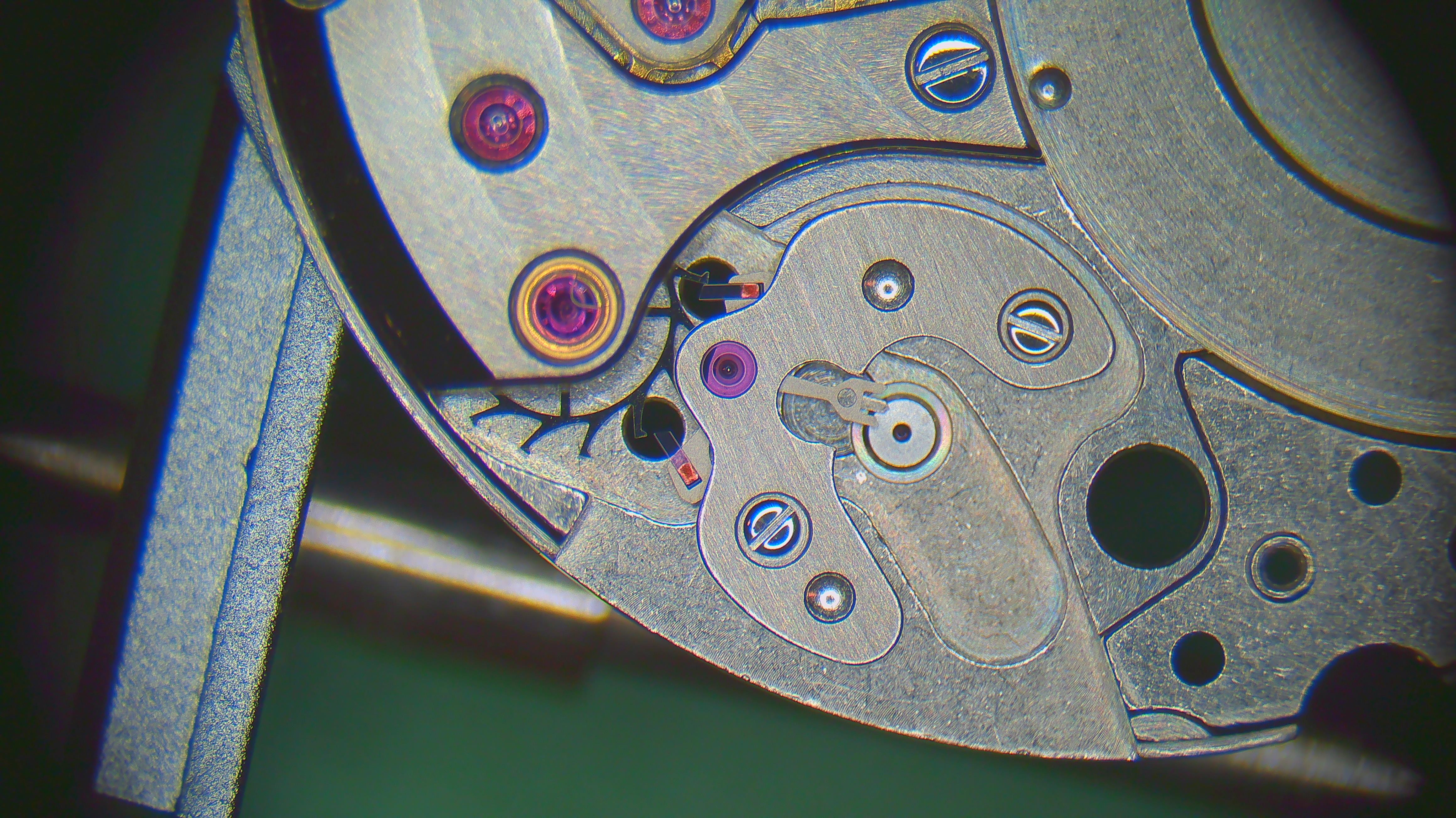
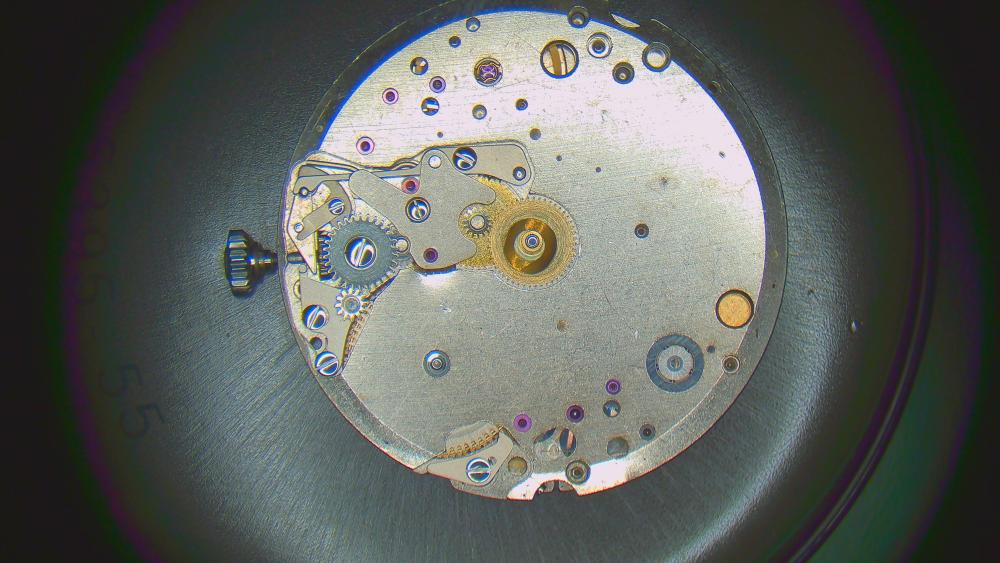
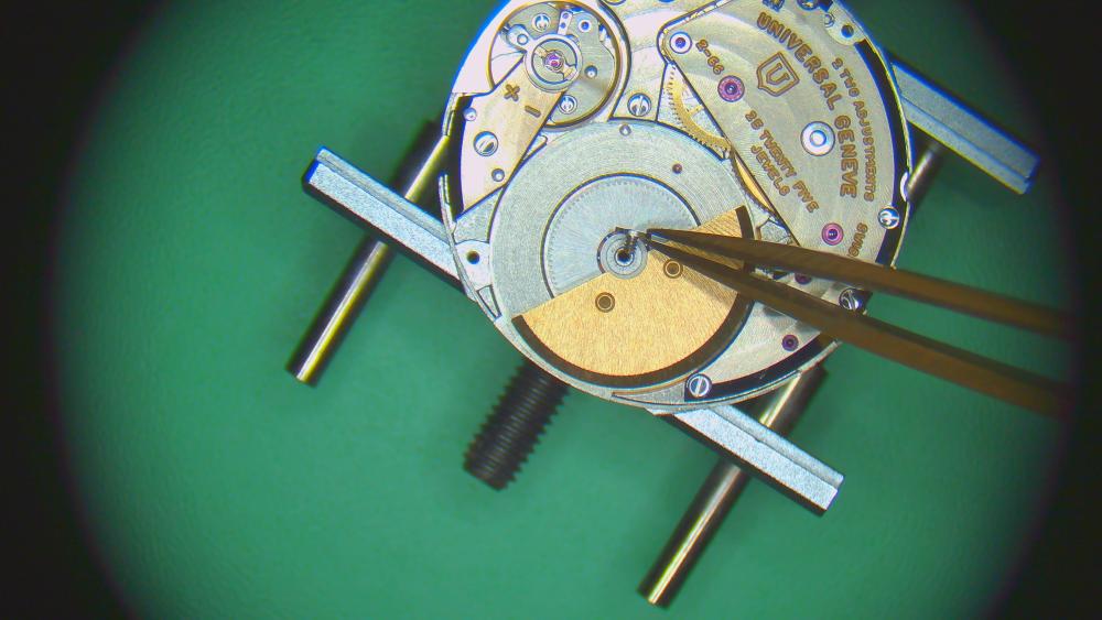
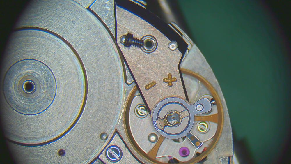
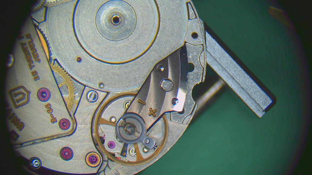
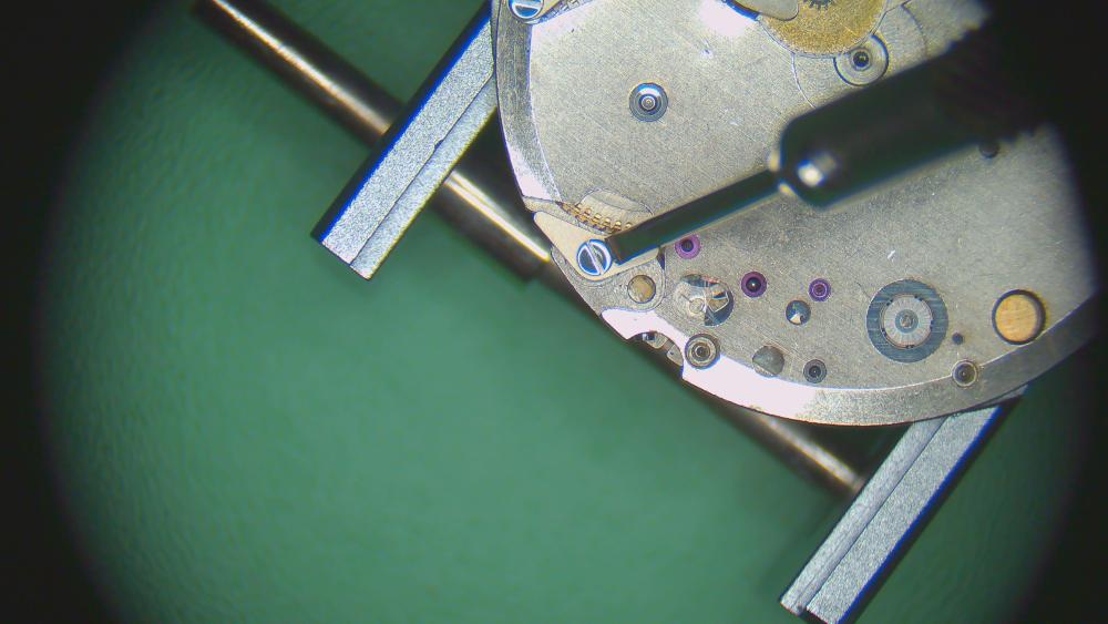
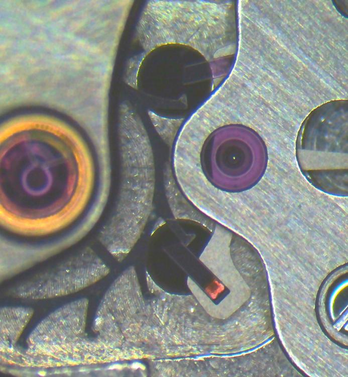
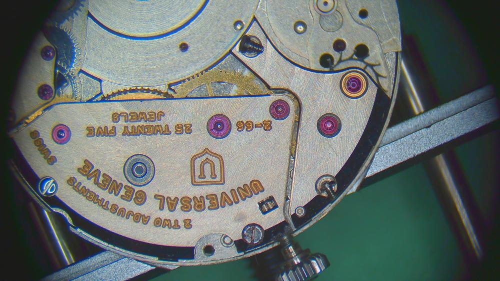
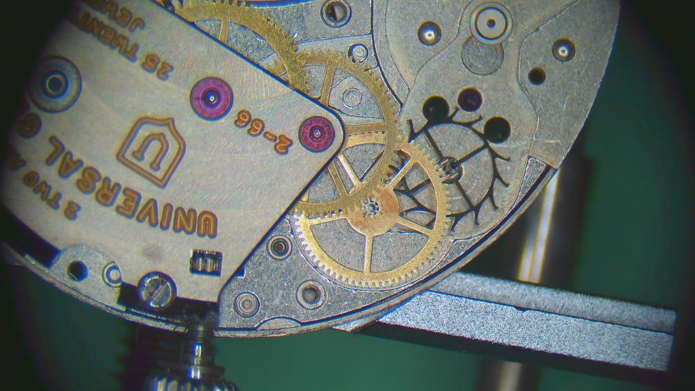
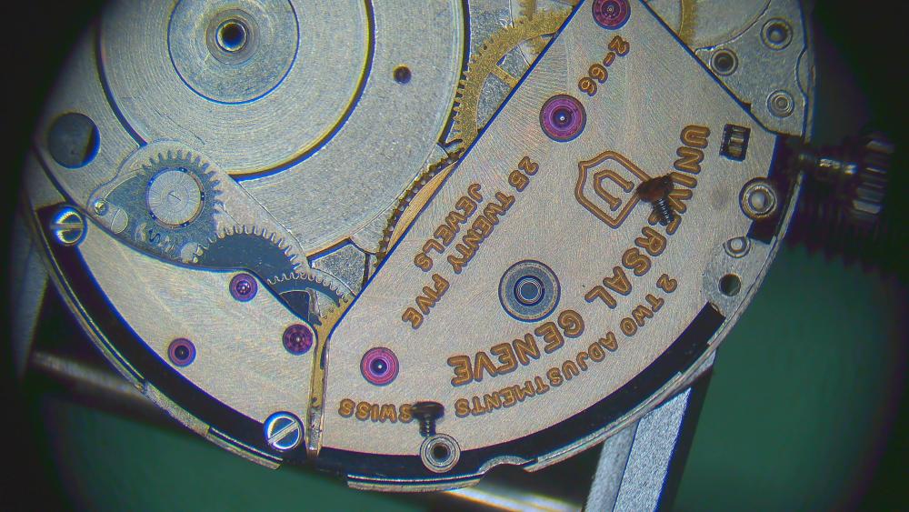
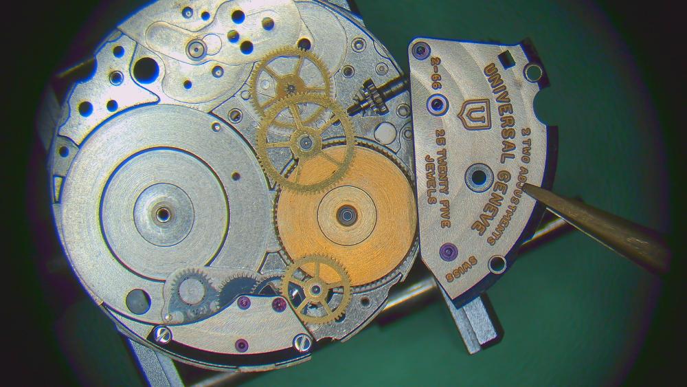
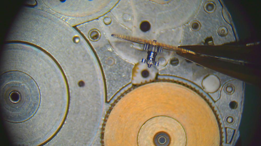
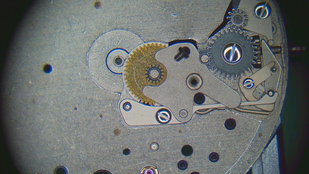
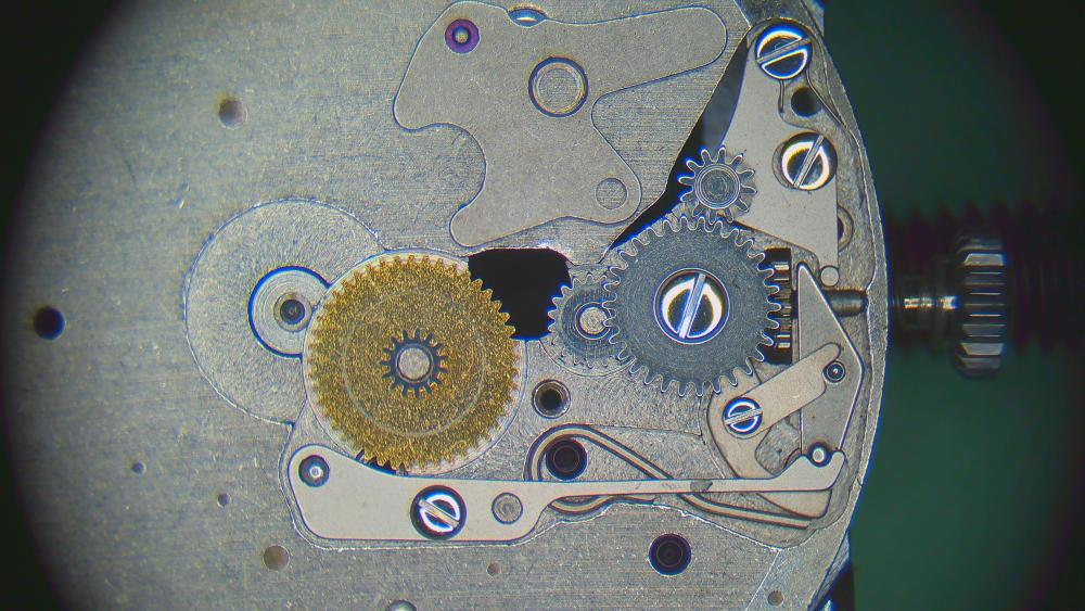
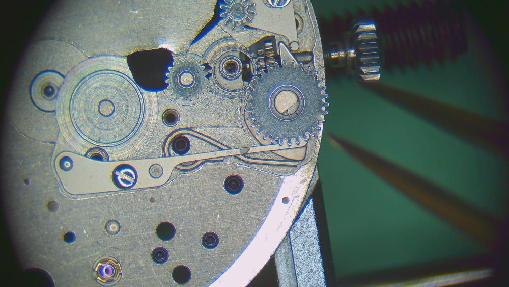
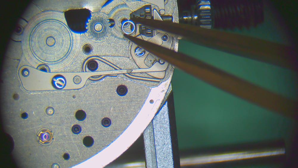
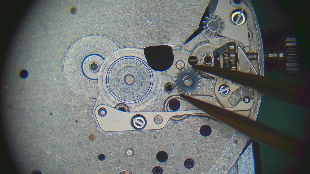
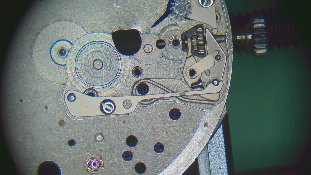
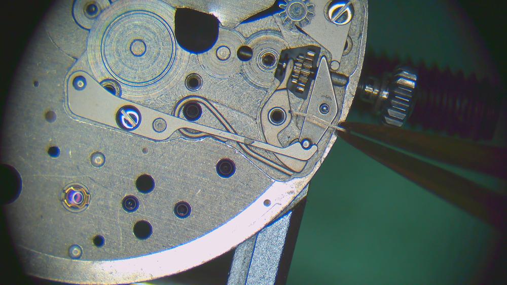
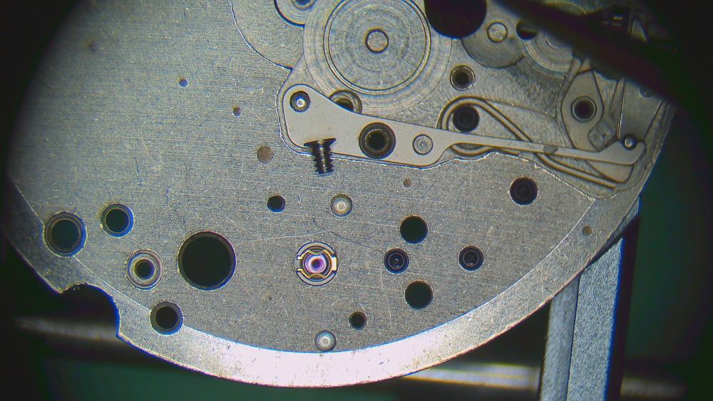
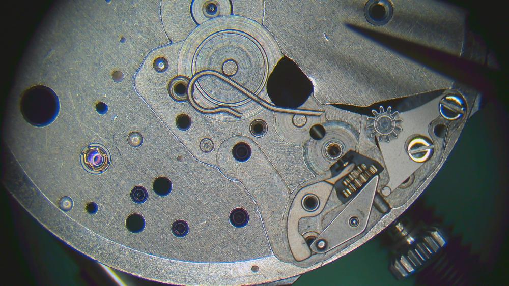
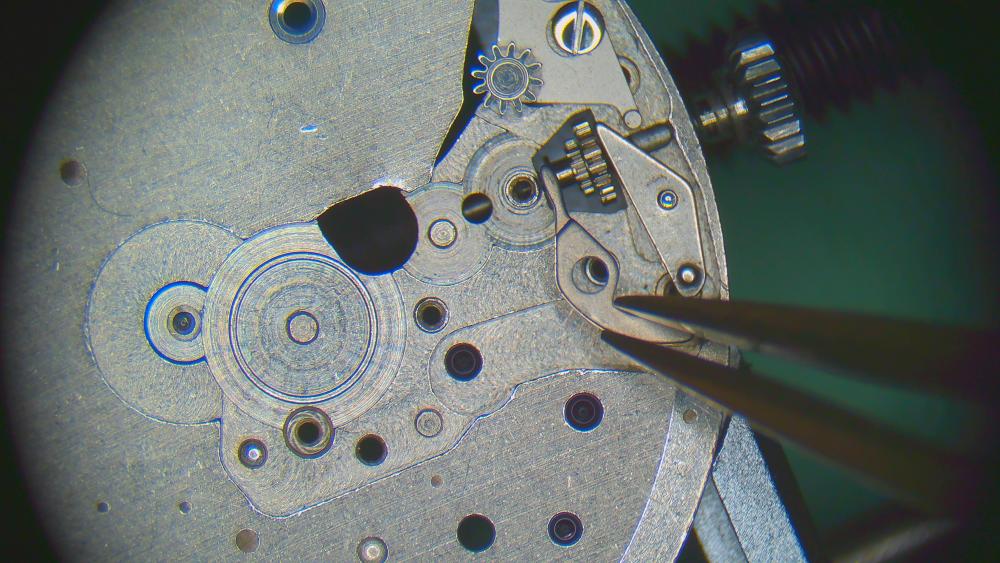
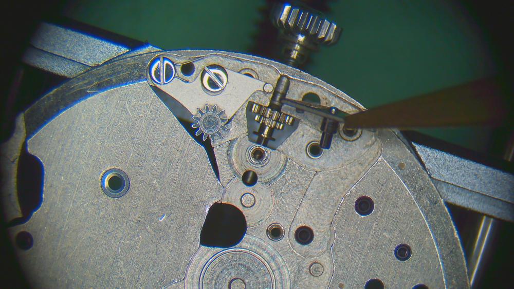
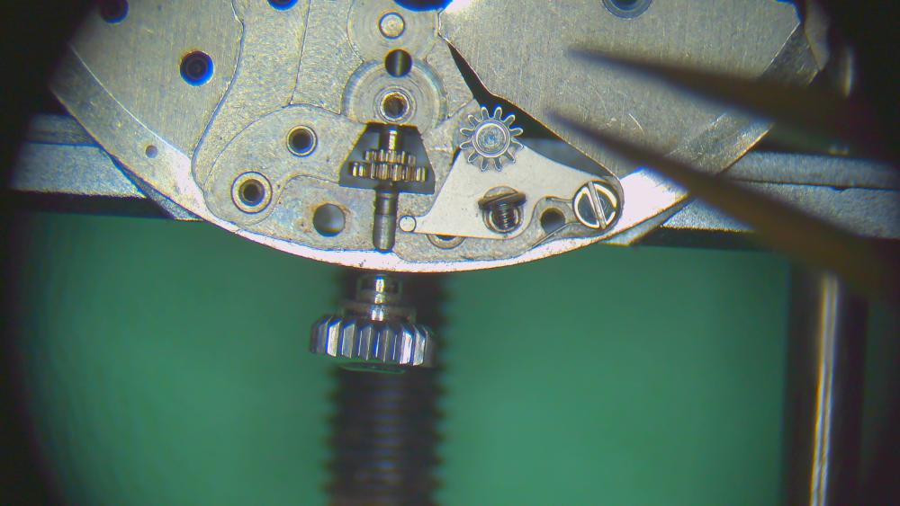
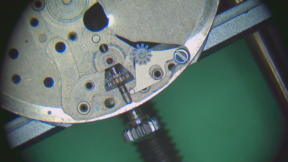
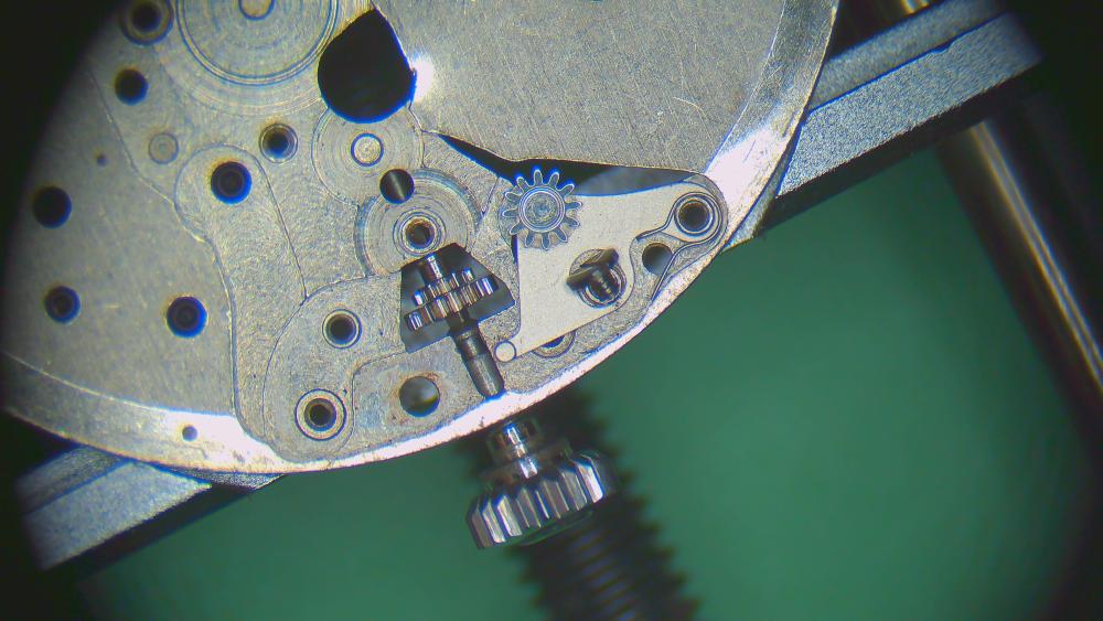
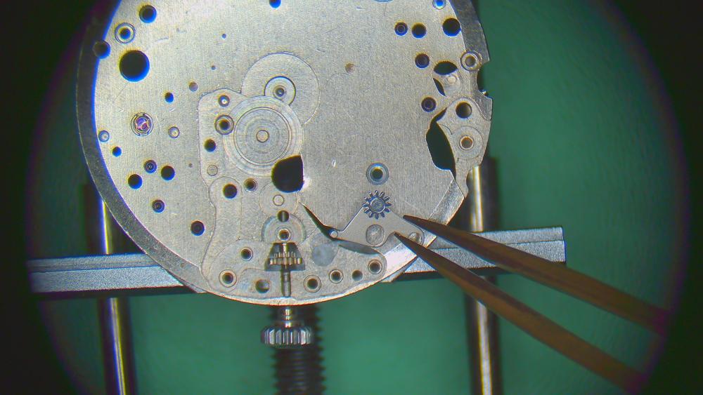
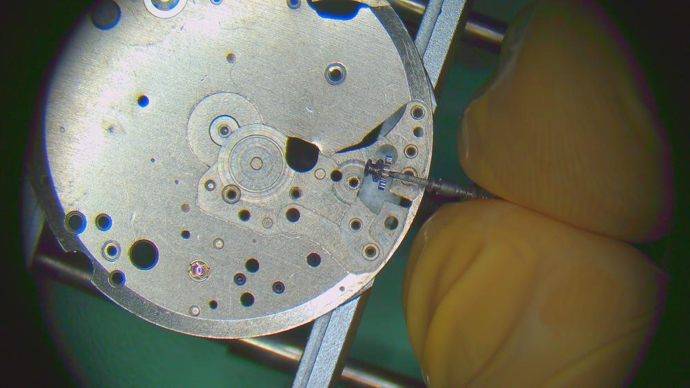
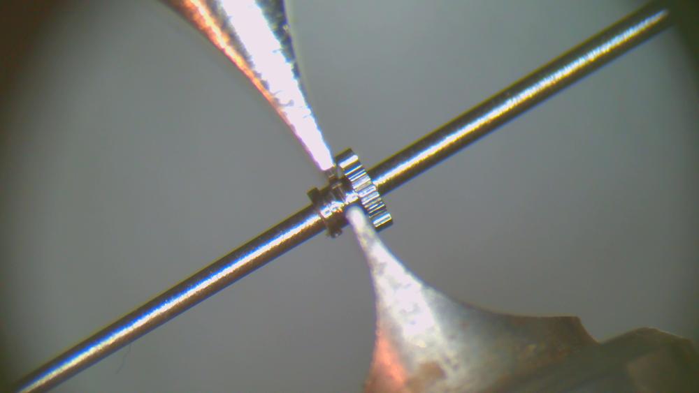
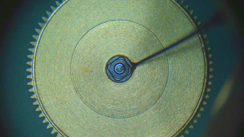
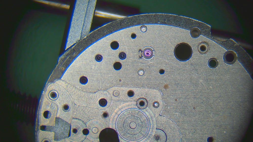
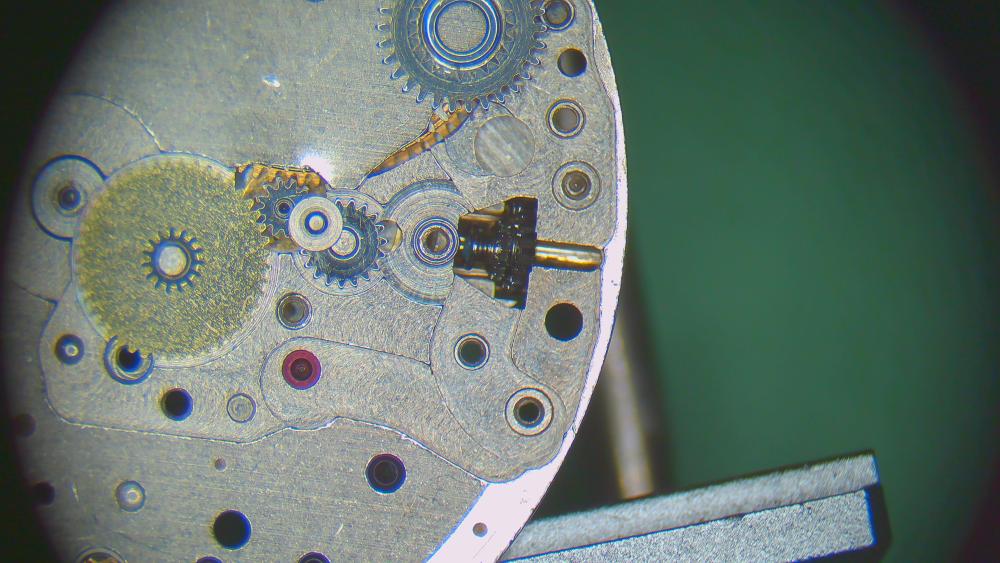
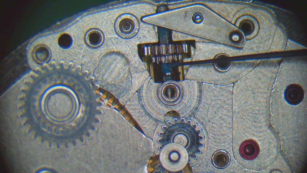
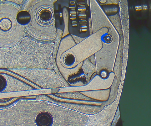
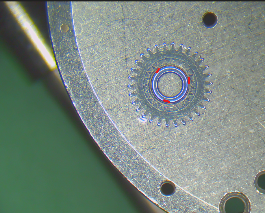
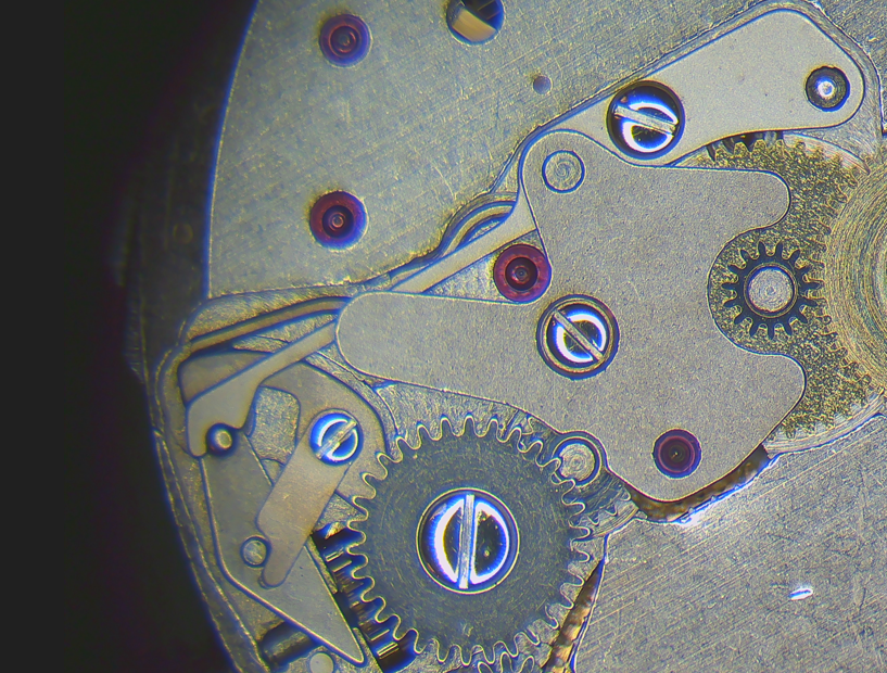
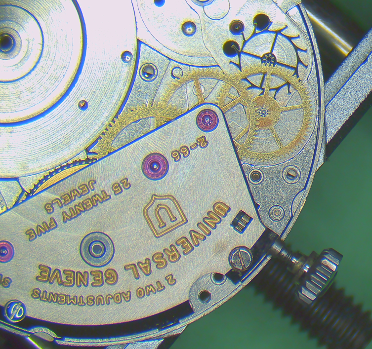
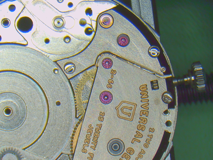
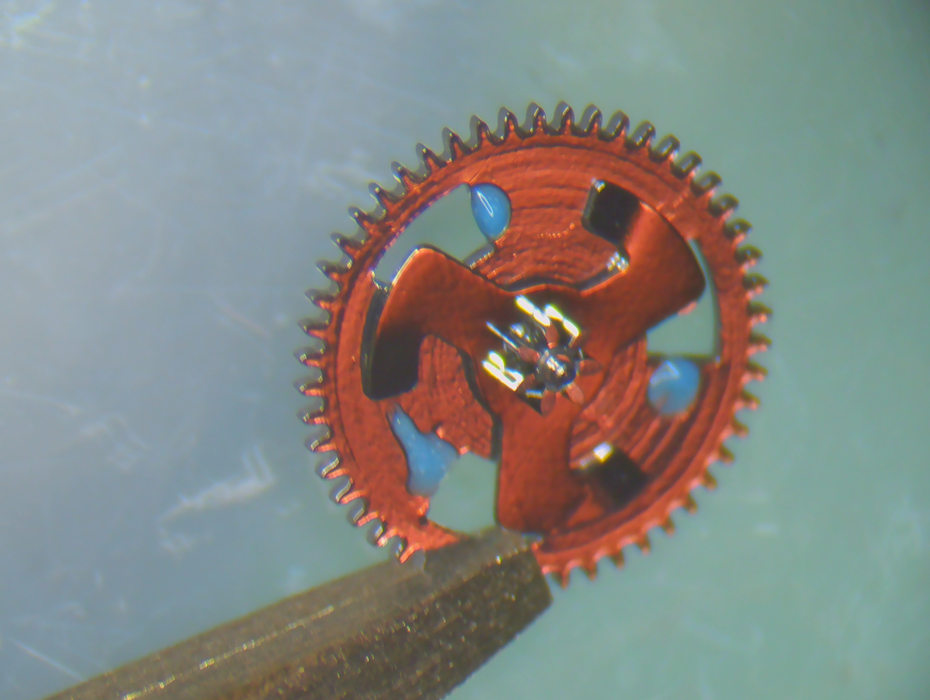
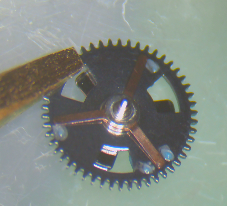
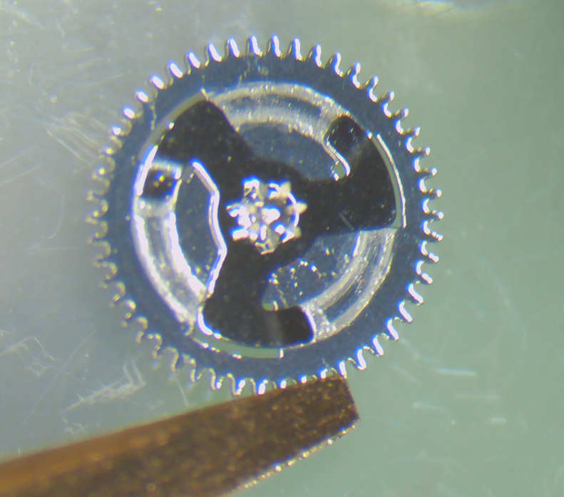
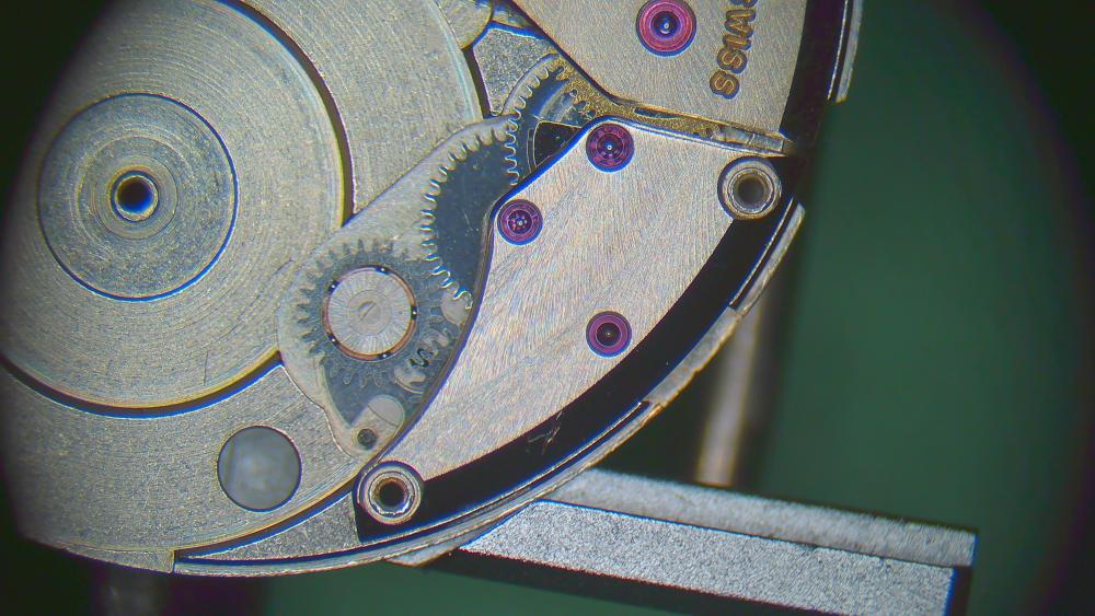
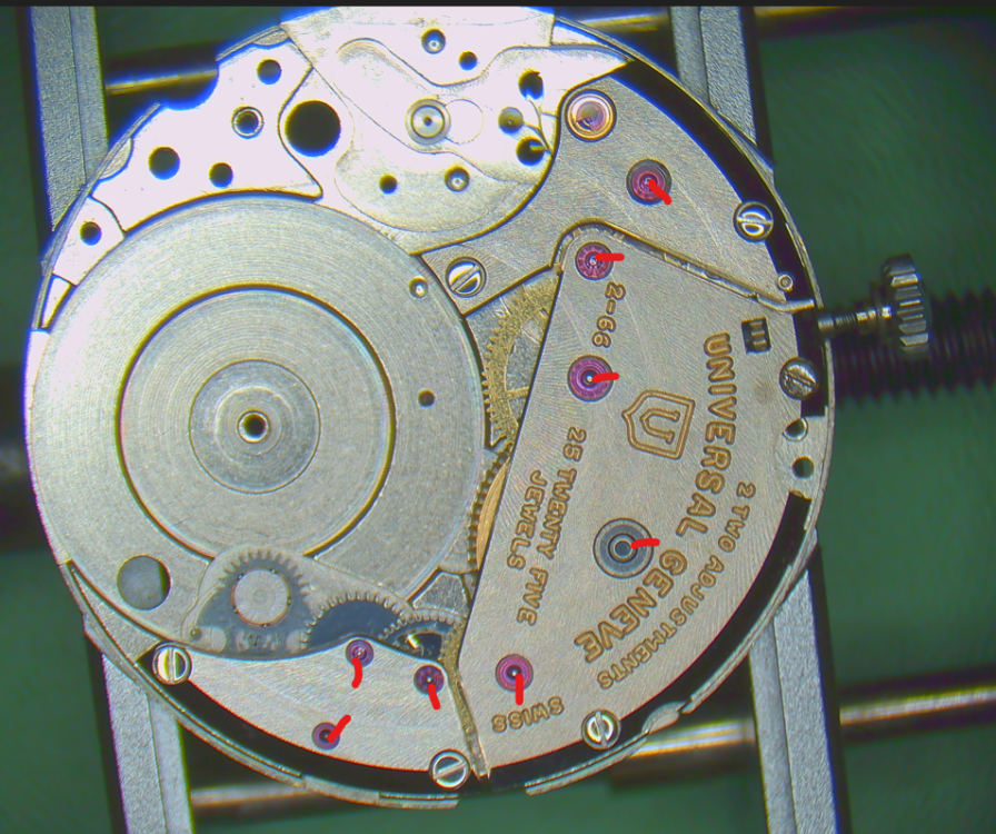
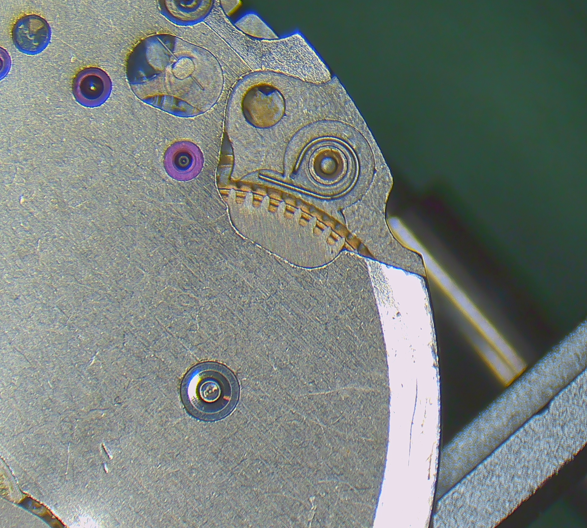
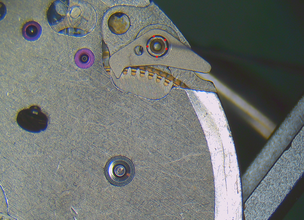
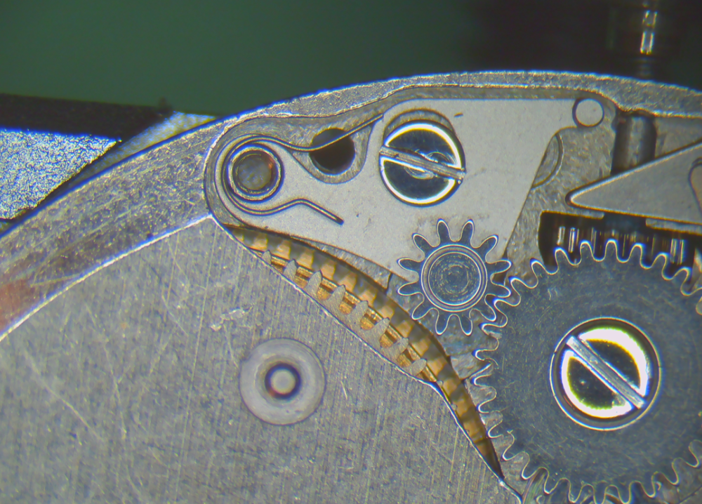
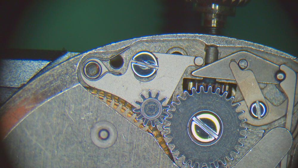
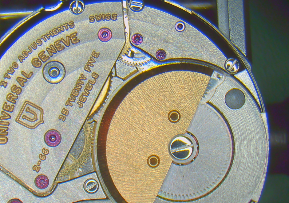
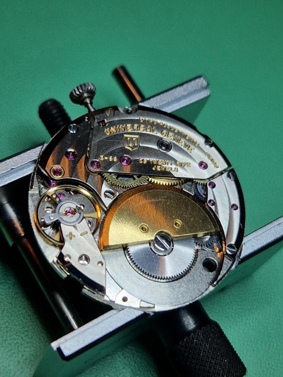
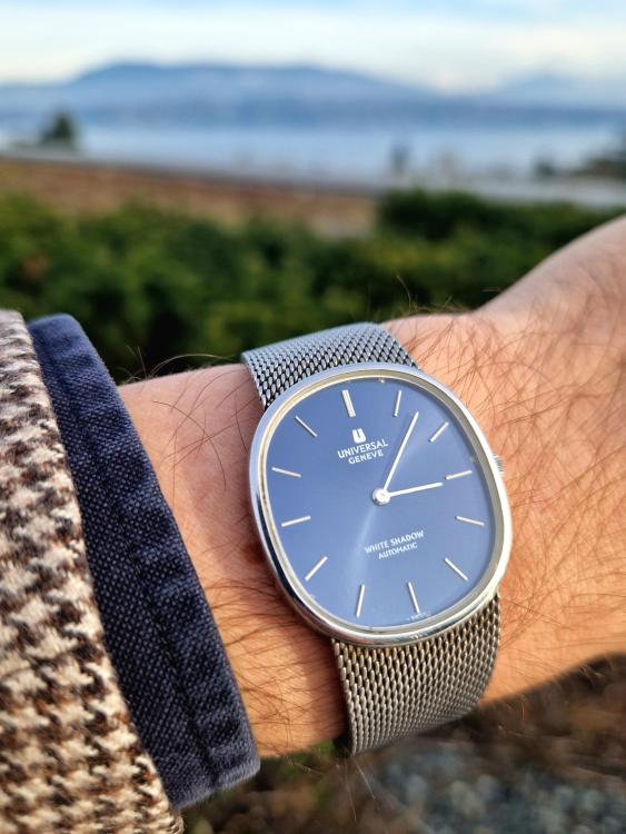
Good morning! My next walk-through. This time of an Universal Geneve 2-66 calibre in a "White Shadow" watch. With less than 2.5mm thickness, the movement was one of the thinnest automatic movements at its introduction in 1966 and for decades to come. Some say it was the thinnest of all, but I found the Piaget 12P was 2.3mm and introduced in 1960. That would make the Universal 66 the second-thinnest automatic movement unitl 1985 when the Frederic Piquet 71 came in with 2.4mm. ANYWAY, it's very thin! Another cool story is that no other than Patek Philippe poaches the movement engineer of Universal and let him basically copy the UG 66. They then introduced the Patek calibre 240 in 1977. They looks strikingly alike. Apparently, Universal sued Patek, but settled out of court and then went bankrupt during the quartz crisis. (see my post here for a picture comparison of the UG and the Patek: https://www.watchrepairtalk.com/topic/3470-which-watch-have-you-got-coming-in-the-mail-show-us/?do=findComment&comment=270754 ) As usual, I'll share the walk-through in several posts. Today: disassembly. Hands and dial off reveals the keyless works (two dial screws) Note: the dial washer doesn't fit too well. I'll look for another one for assembly. NOTE on letting the power down! The power is held by TWO clicks. One directly at the ratchet wheel (dial side) and one in the automatic works. I first completely removed the click at the ratchet wheel and then held back the click of the automatic works. It worked ok, BUT is not ideal. It lets the rotor spin to release the power in that direction (instead of the crown). I therefore suggest to first remove the automatic works completely (rotor, wheels and click). THEN proceed as usual by holding back the ratchet click and releasing power gently by holding/slipping the crown. To show the (supposed) better practice, I'll post my pictures in a different order from my actual disassembly. This is how I think it SHOULD be done (in retrospect), 0. Remove the balance 1. Automatic works: remove the rotor The automatic bridge (please ignore that the barrel bridge is already off and don't remove it before releasing the power!) VERY gently with this spring on the click! It's insanely thin. The end of the spring rests in a small hole in the mainplate. I'll show that in my pictures for assembly. Note that the wig-wag winding wheels for the rotor can stay in place. They are riveted to the movement. A total of three ball bearings here! Two are visible, and the backside of it (that wigs and wags) also has a ball bearing. The rotor also has one. So four ball bearings in the movement!! 2. Turn movement over and release the power with the usual method (hold back click and gently let the crown slip through your fingers) The click is here: Then disassembly the click I also took the hour wheel of (no picture, but obvious). NOW, IMPORTANT. The apparent cannon pinion here, is not a real cannon pinion!! It should be completely free. The movement doesn't have a central centre wheel and therefore the "true cannon pinion" also isn't in the centre of the movement. This "false cannon pinion" is just a reduction wheel for the minute hand. DO NOT have the stupid idea of tightening this "false cannon pinion".... like I did ... But ok, onwards. 3. After letting the power down, I go back to the train side. Note on pallet fork: the lock is very heavy. If amplitude turns out to be very low after service, I may have to push the pallets in a bit. Note that there a two different screws for the train bridge!! The one on the edge is a bit shorter. Barrel bridge. Again, note that there are two different screws! The one at the crown is longer. Now, the larger wheel next to the barrel is the decentralized centre wheel with cannon pinion. I will show how to disassemble it in a later post. The ratchet wheel is under the barrel 4. Dial side cover plate Watch out, under this wheel is basically the crown wheel. There's an outer crown and also a seat around the post. the downwards bent side goes down on the setting lever careful, very strong spring here this lever engages and disengages the integrated wheel directly with the ratchet wheel for manual winding Now again very careful with the spring under the lever! It is very thin and very springy. I actually lost it and couldn't find it even after 1.5h on the floor... and since I managed to buy one, there are now only very few left in the world! finally the stem with the pinions removing lower balance jewel for cleaning barrel open. NOTE that the square bit of the barrel arbor points up from this perspective (not pictured). This is important to remember for assembly. This concludes today's post of disassembly. Next post will show the disassembly of the integrated decentralized centre wheel and true cannon pinion -- and tightening it (because it was slipping).


 1 point
 -
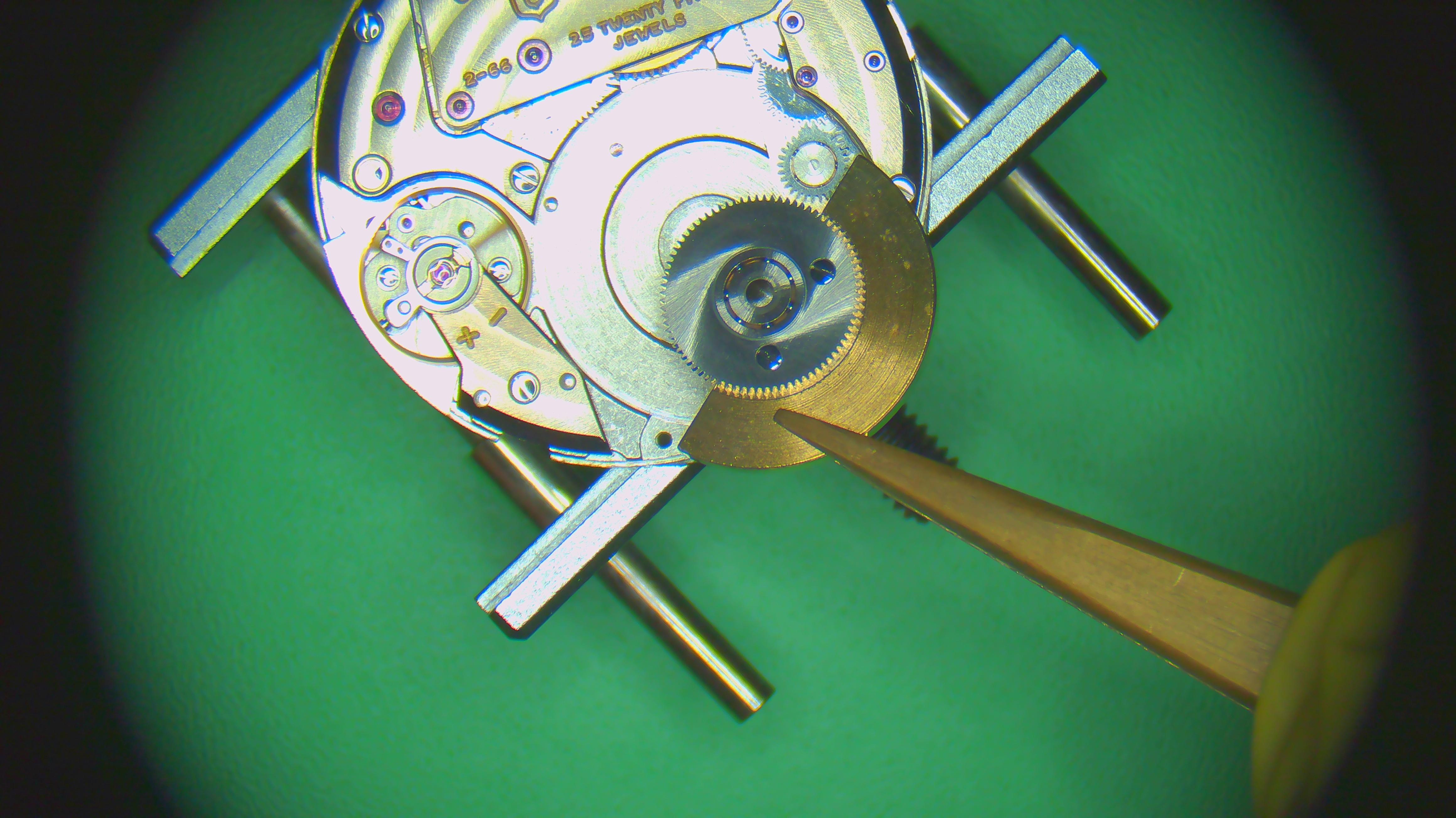
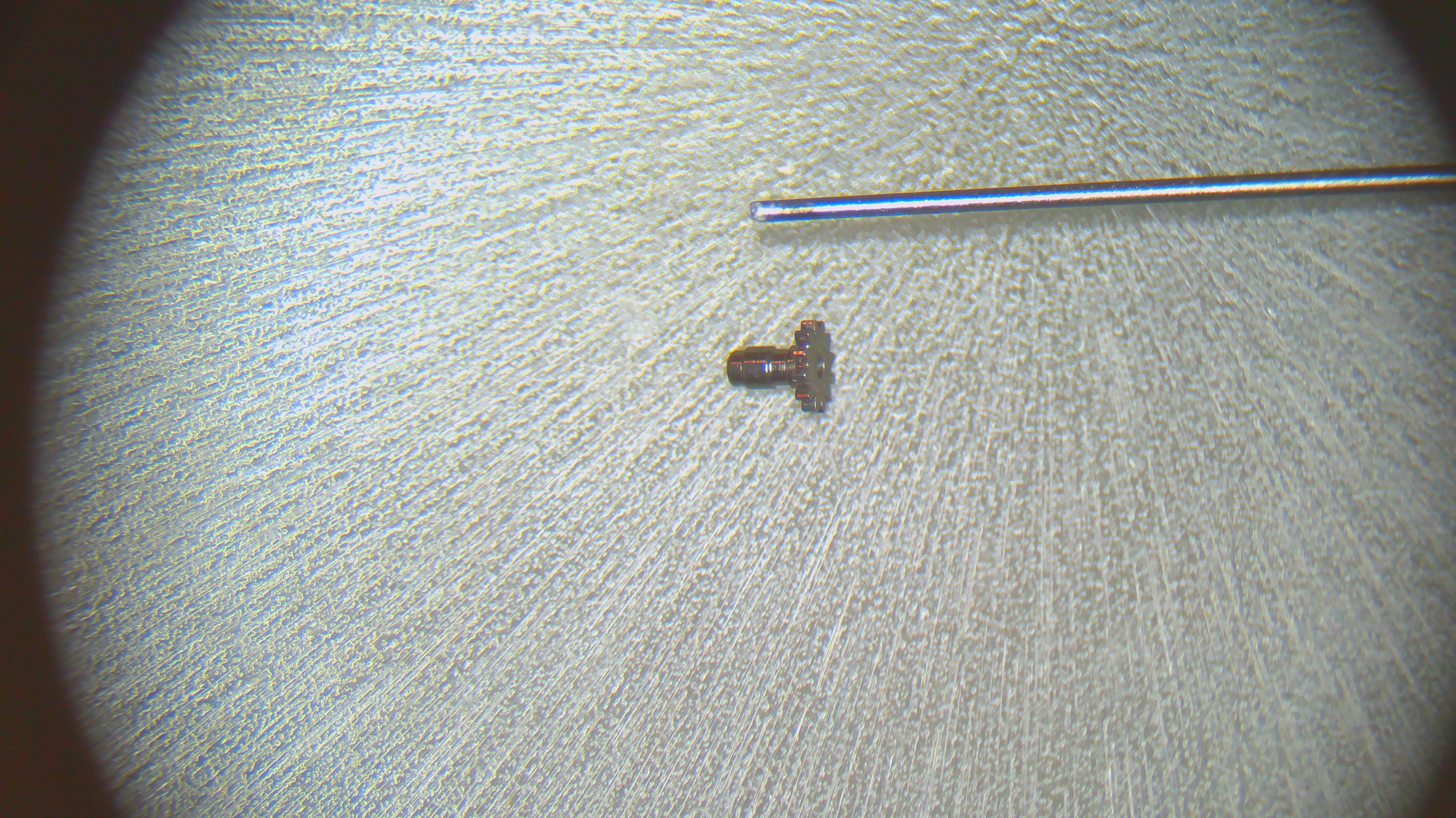
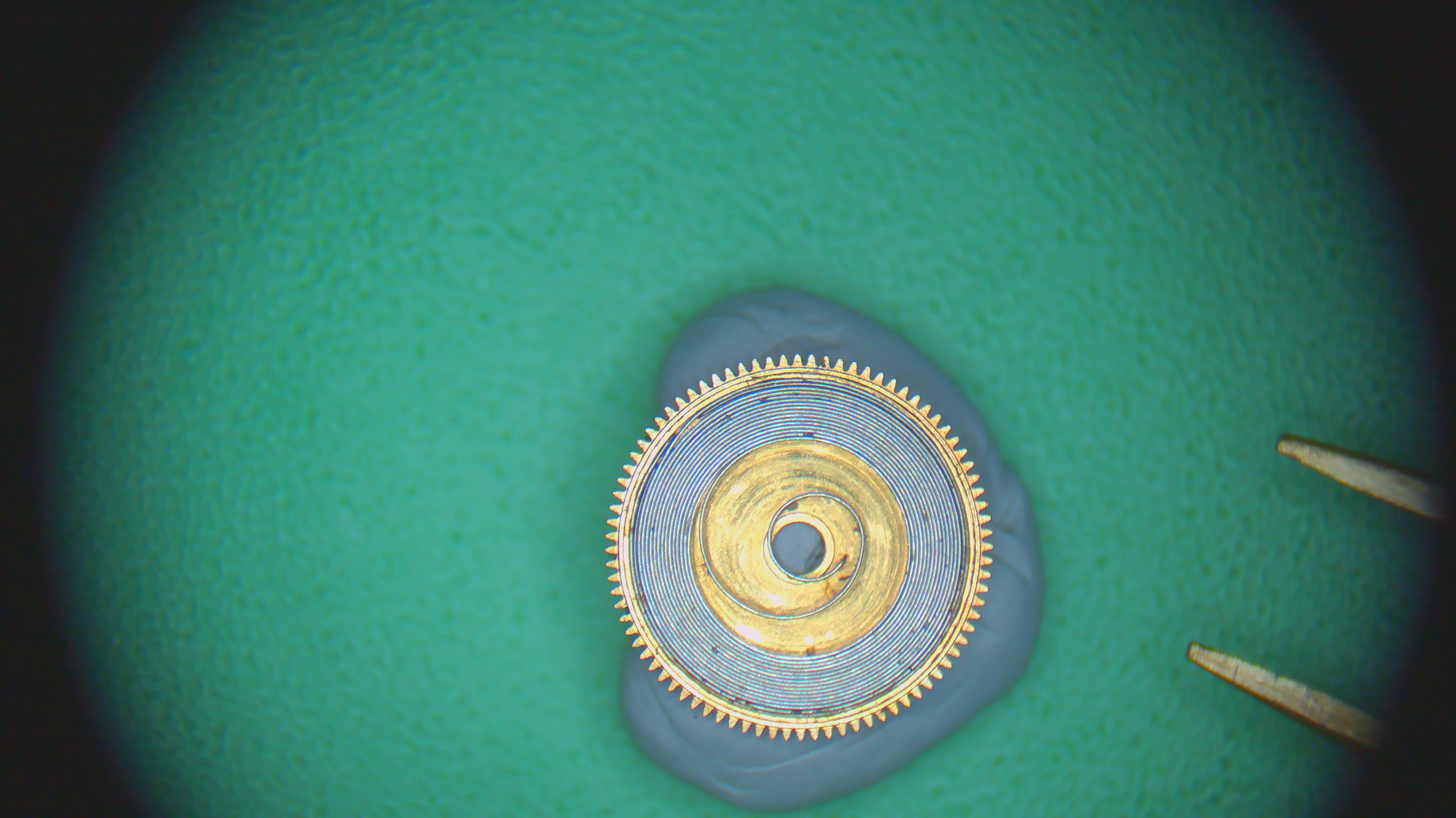
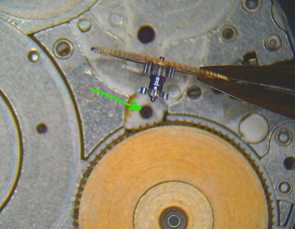
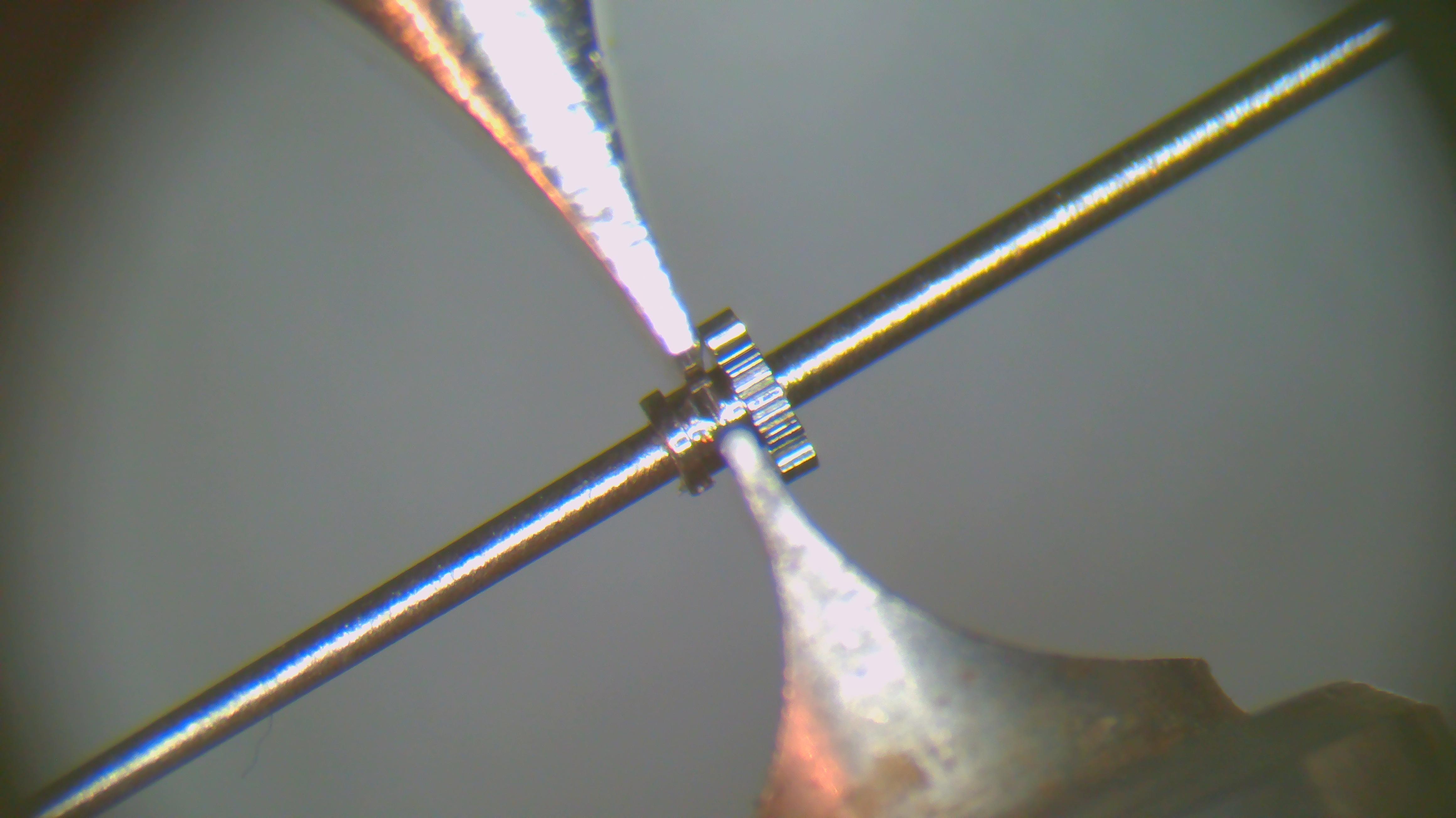
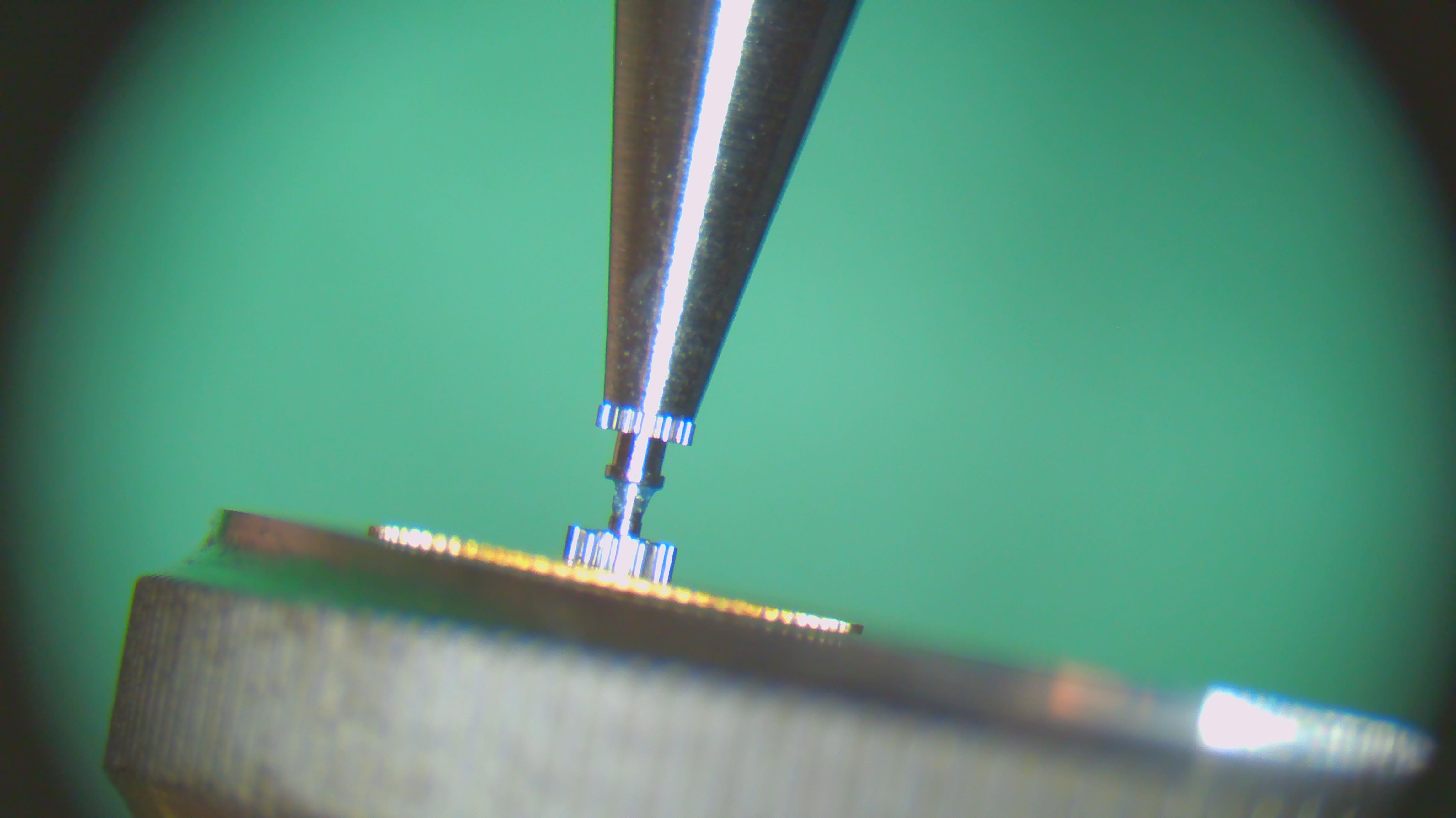
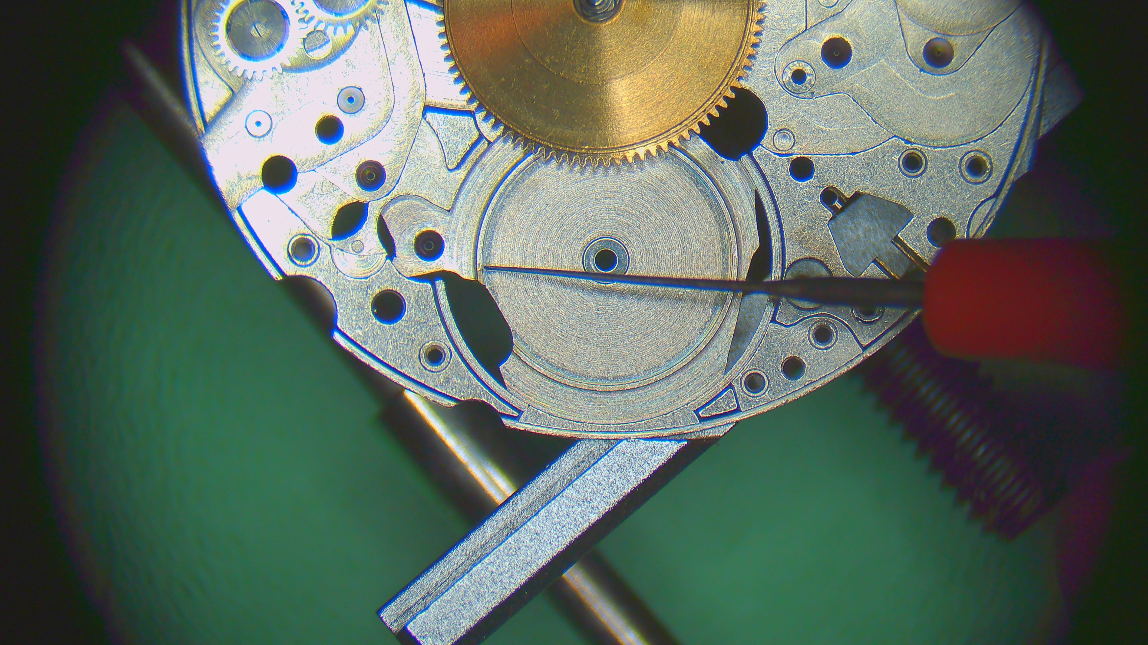
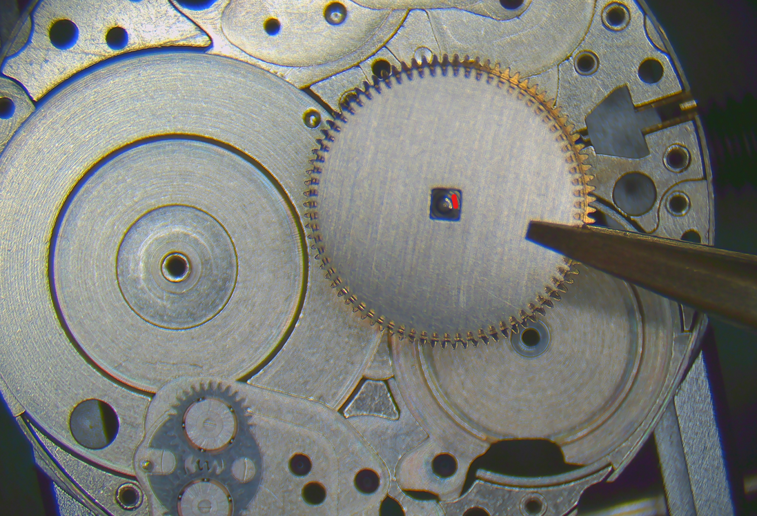
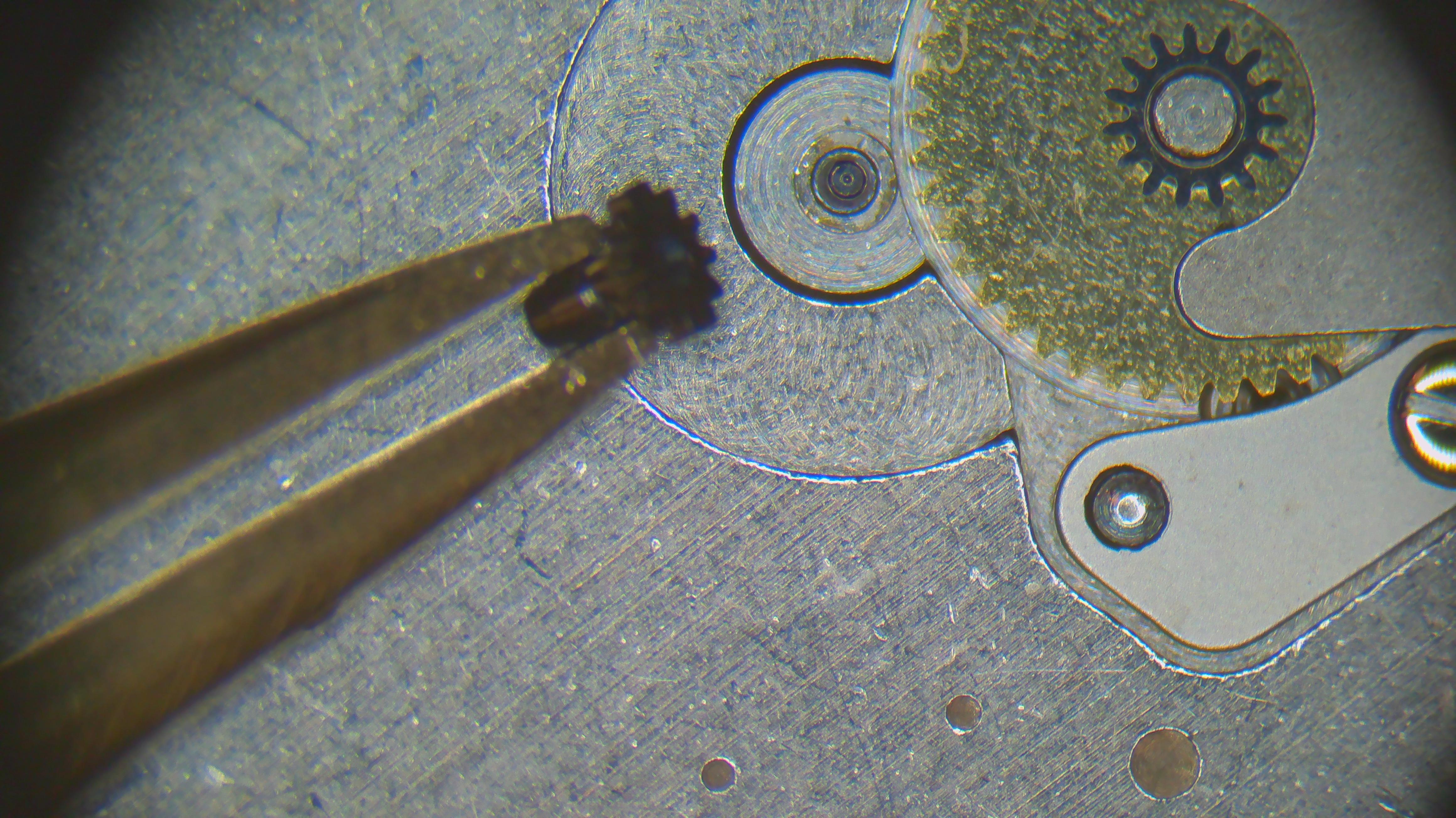
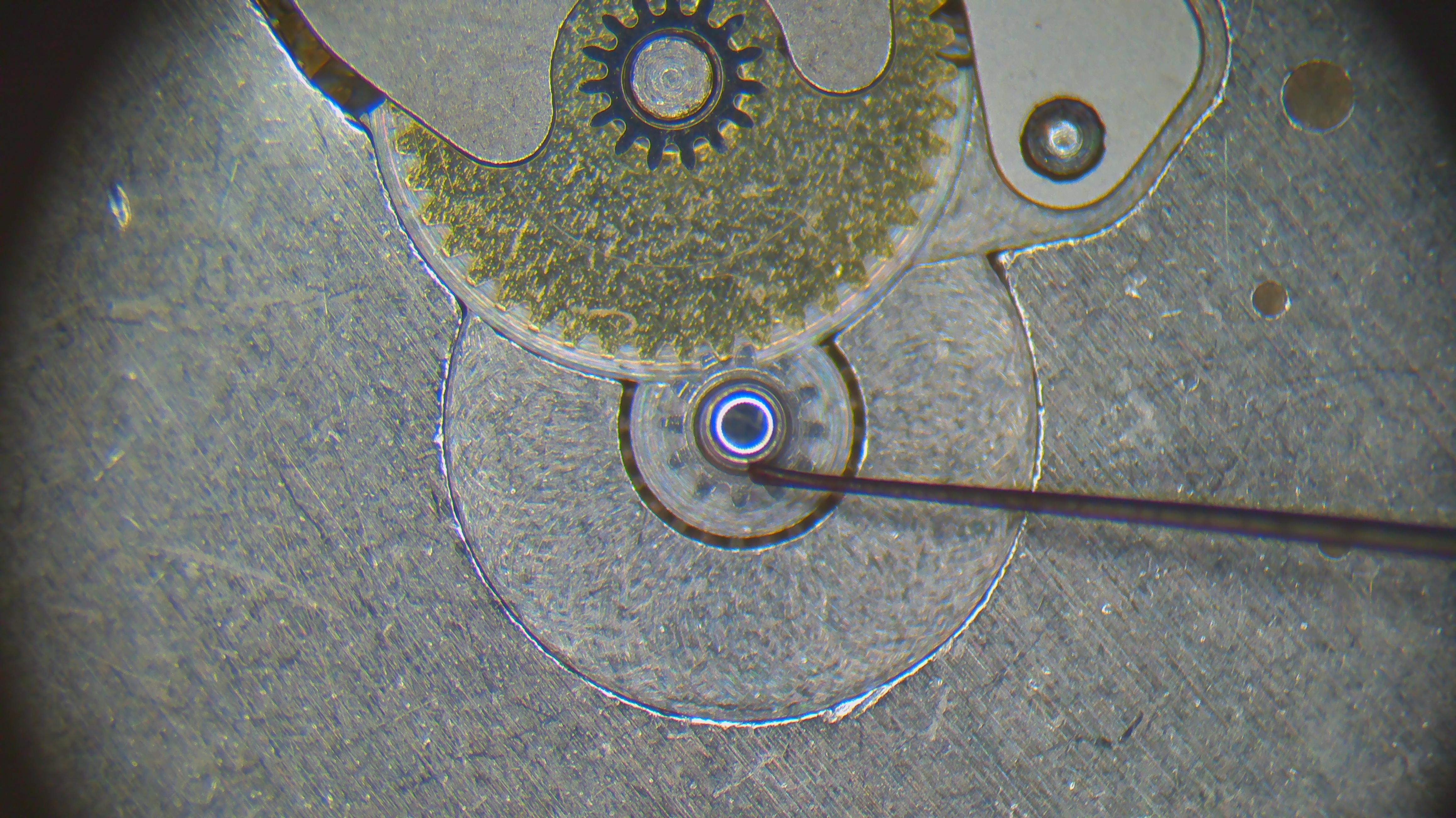
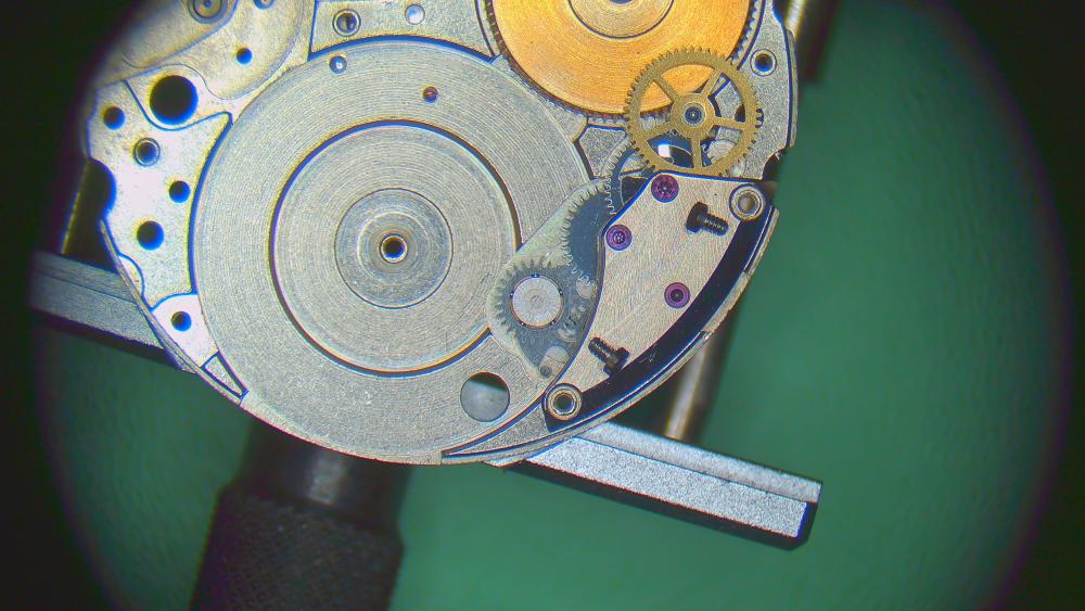
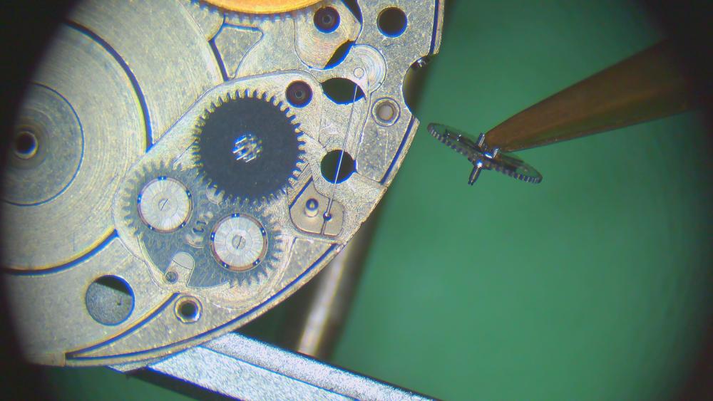
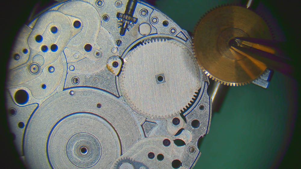
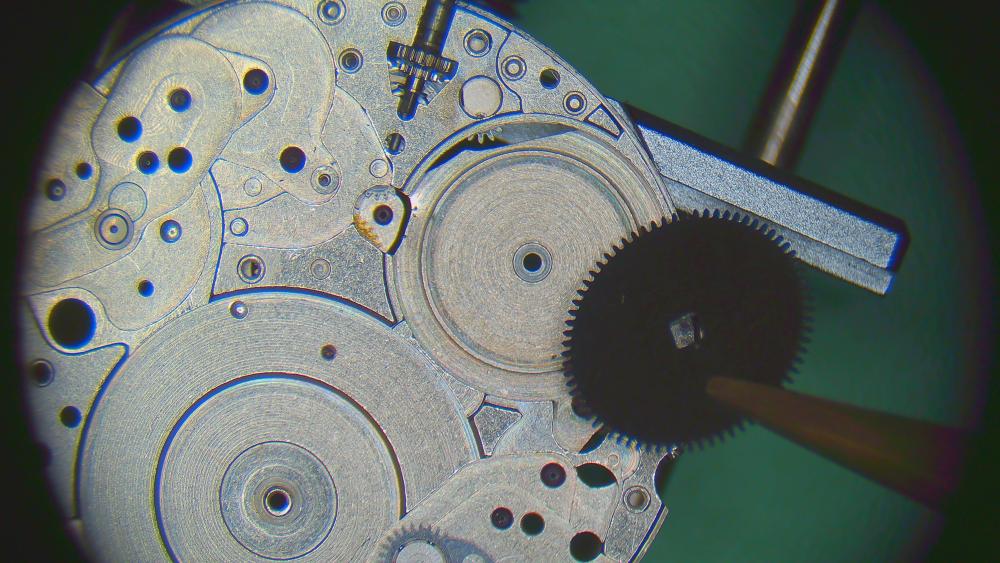
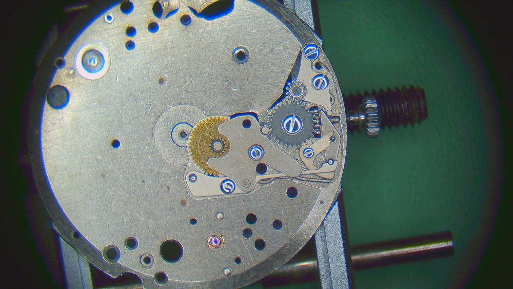
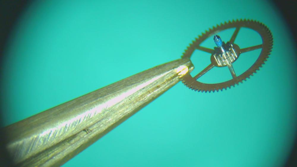
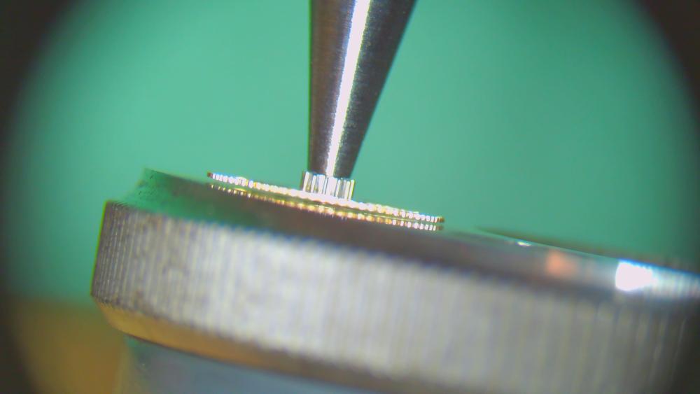
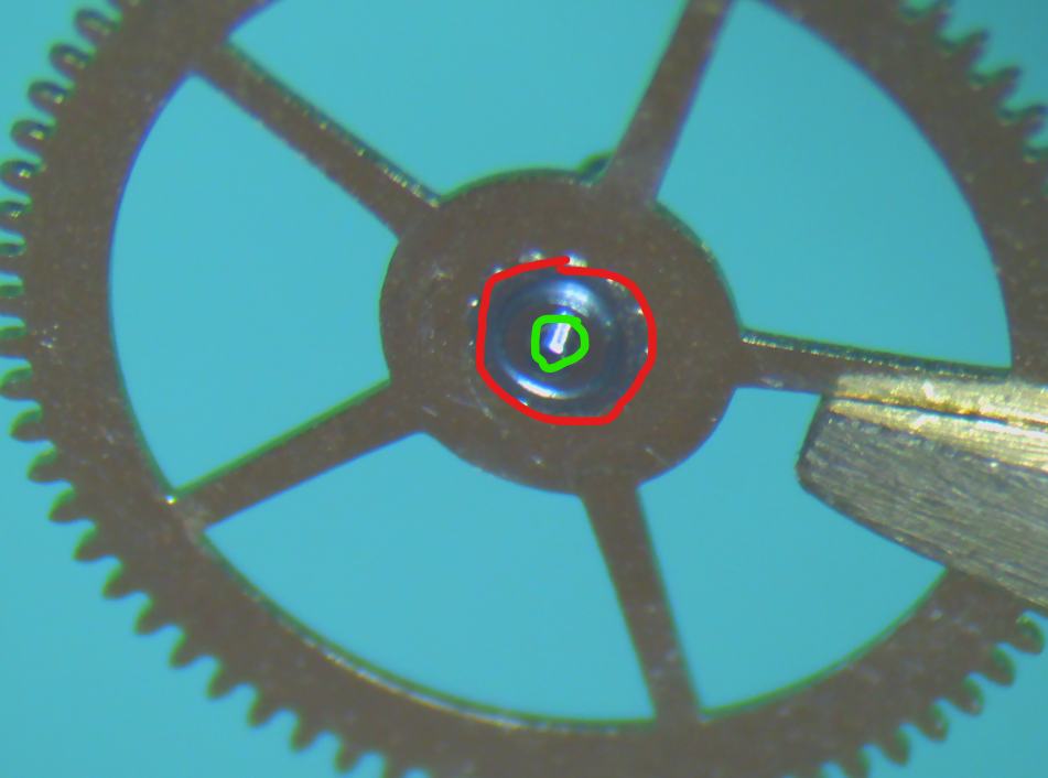
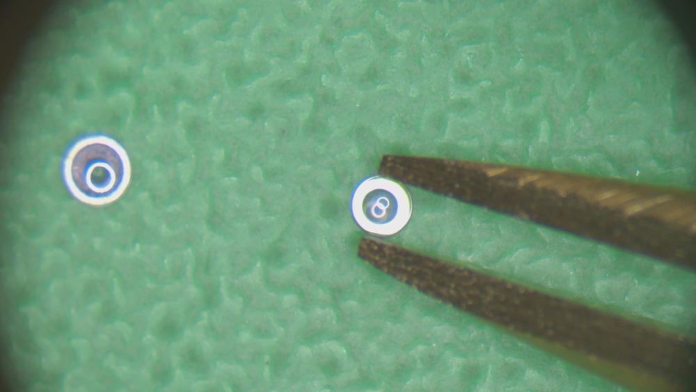
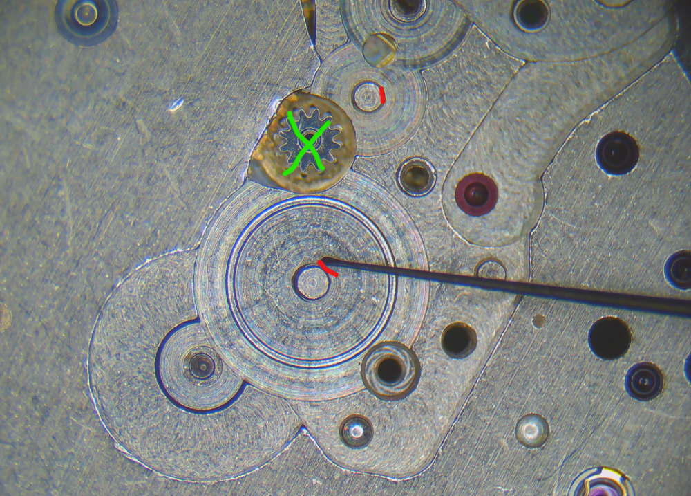
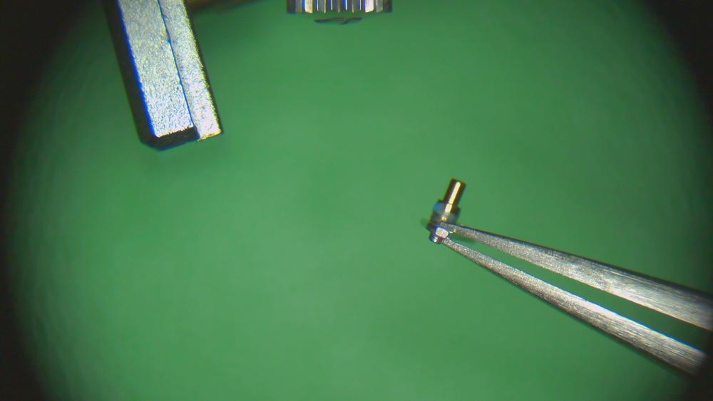
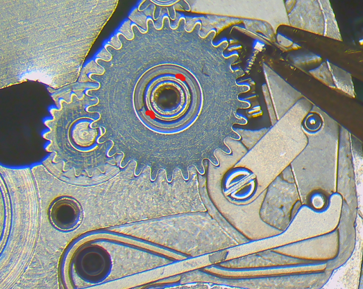
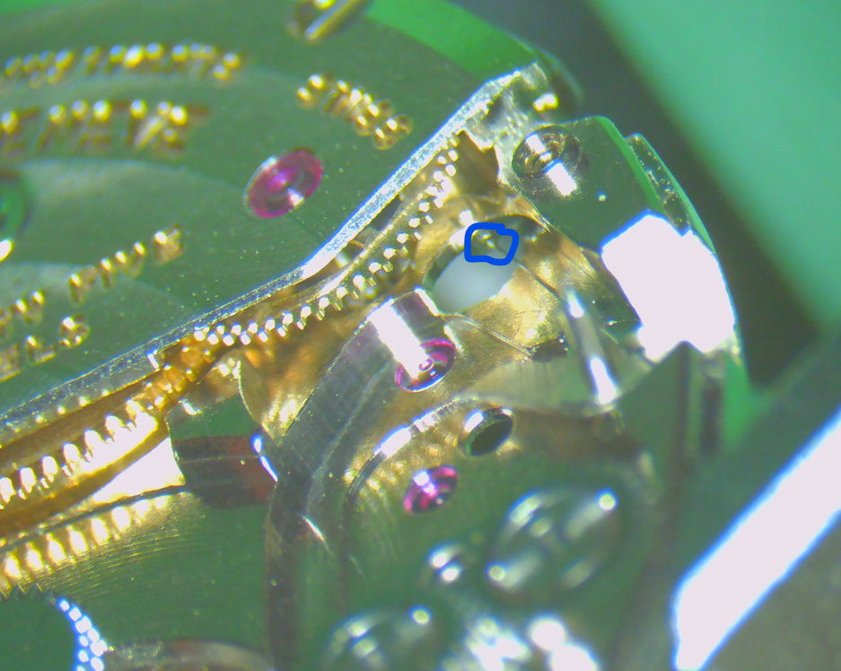
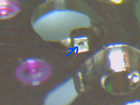
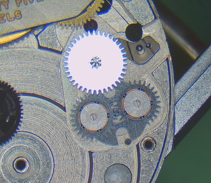
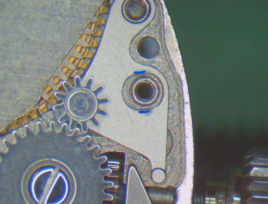
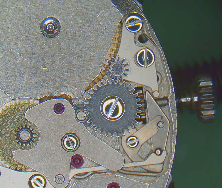
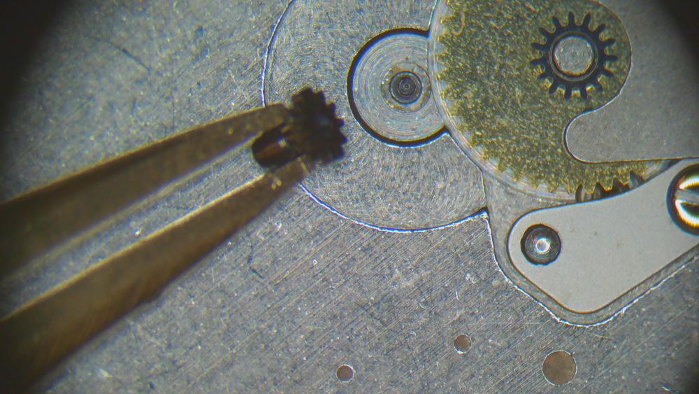
Ok, next one! First, the cannon pinion! Remember, this is the decentralized cannon pinion with integrated cannon pinion (and it goes where the green arrow indicates): First challenge: how to disassemble!? - do not use a Presto tool with its "feet" against the spokes/rim of the wheel! It'll bend the wheel. - using a scalpel or razor blade to slide between wheel and cannon pinion is also not working well --> I cut a triangular wedge into a spare barrel lid (of course, any other thin sheet of metal will do). Then I slide it between the two steel pinions, like so: Now I can use a presto tool to lift off the cannon pinion. Make sure the wedge is properly between the two steel pinions! No force should be on the brass wheel. Clean. In my case, the cannon pinion needed some tightening: Grease the staff of the (decentralized) centre wheel. I used 9504. To combined the two parts again, on the staking set, make sure the top punch fits over the whole staff of the centre wheel. It'll protrude from the cannon pinion and you don't want to punch on the staff.. Secondly, note that the wheel seems to "hover" over the staking block. You want to chose a hole on the staking block that just fits the green circle here, and NOT the red one (if you do the latter, you may punch out the staff from the wheel...) Push. Done. Now over to the barrel assembly. I distribute a thin layer of breaking grease around the barrel wall (I used 8217) New spring in (this is 0.70 x 0.1025 x 375, item number 266771 at CousinsUK) remember that the square part of the arbor points upwards close lid. then I oil with HP1300. Epilame treatment of pallet stones... ...and escape wheel (full submersion and then removing epilame again from the pivots) I take advantage of the balance still being installed on the movement (from cleaning) to oil the balance jewels on both sides of the movement. Just two pictures. It should be clear otherwise. 9010, of course. Now, disclaimer. Like in the assembly, I realized half-way through assembly, that another order would have been better. So I'll post the pictures in the order that I think is better. So please ignore the presence of some parts that were already installed in my less efficient, actual assembly process. I suggest starting with the keyless works before installing barrel bridge, train and automatic works. Why? The "decentralized" centre wheel and cannon pinion is held on the keyless side by a jewel in the cover plate for the keyless works. If you don't have that installed first, it's making the installation of the barrel bridge a bit tricky. So, first the pictures of the keyless works assembly. HP1300 on the posts (ignore presence of centre wheel here) add respective wheels and the seat for the other post place the pinions/wheels for the winding stem setting lever with some 9504 setting lever and stem replaced and adding some more 9504 (I spread this amount around by turning the stem while holding the oiler there) placing the yoke, adding some 9504 on the sliding points (excess will be removed later with rodico) and then the yoke spring unfortunately, I forgot to take pictures of the next steps, so I'm borrowing pics from disassembly. set lever jumper with 9504 as indicated and a bit of 9504 here combine the two parts of the crown wheel and the winding wheel and add HP1300 between them as indicated then add HP1300 on the seat and install them install the cover plate turn movement over add the tiniest amount of HP1300 to this rim (or don't, but don't let it flow over) combine ratchet wheel and barrel and replace them jointly (to get ratchet wheel into the right spot immediately and not smear the oil on the aforementioned rim). HP1300 on the arbor pivot as indicated. place wheels and then the bridge now the train wheels the 2-66 movement has this unusual fixed cap jewel for the escape wheel. I oil it from below and push the 9010 through with a sharpened oiler. Inspect size and position of oil circle from the top side. install train bridge I choose to proceed with the automatic works now first the secondary click (for auto winding intermediate driving wheel). the tiny spring needs to go through a small hole where indicated view from the other side of the movement place the intermediate winding wheel now there's this special wheel which which disengages the automatic works when the watch is wound automatically (same as JLC 889 that I serviced recently). The slipping "arms" need some grease (or oil). I used 9504 I then spread it around by gently moving the arms around (clockwise in below picture) place the wheel and install bridge I decided to use HP1300 on all these pivots (escape wheel pivot was oiled previously with 9010). I prefer the higher viscosity oils to avoid any creeping. Happy to drop a few degrees of amplitude for that. turn movement over and install primary click at the ratchet wheel very light use of HP1300 (sorry, screw not pictured) now back to the keyless works again small amount of HP1300 tiny bit of grease as indicated secure with screw and place spring (careful with this one.... it's a highly qualified candidate for the Swiss space programme) arm the spring and secure with screw dial side oiling with HP1300 (red) for everything except the escape wheel (9010, blue) I add a tiny bit of 9504 to the click/teeth here turn over again. pallet fork. as usual, I install the balance, let it run a few minutes. remove the balance. oil the exit pallet stone with 9415. one small drop every 4-5 teeth. then the rotor. NOTE: I didn't oil any of the four ball bearings! This is up to debate.... in some service manuals across different brands, ball bearings are oiled (with 9010 or Lubeta V106 or 9415), in other manuals they aren't. I chose to not oil because the watch case is barely dust-proof. And if any dust gets inside, it'll attract to oil. If it gets on the ball bearings, it'll quickly clog up. But happy to receive other opinions. and the complete train side then back to dial side again. Oiling the inside of the "false" cannon pinion with HP1300. then the outside with HP1300 and place hour wheel and dial washer a bit of regulating. Note from disassembly that the pallet stones lock was a bit excessive. The amplitude could probably be increased by moving them inwards a bit. But I'm happy with this result as it is and will let it be. Since I haven't done pallet stone manipulation yet, I don't want to practice on a movement where spare parts are extremely rare and expensive (the company has been out of business for about 50 years). dial (two screws) and hands on That's my new baby!


 1 point
 -
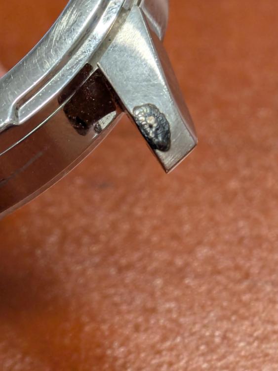
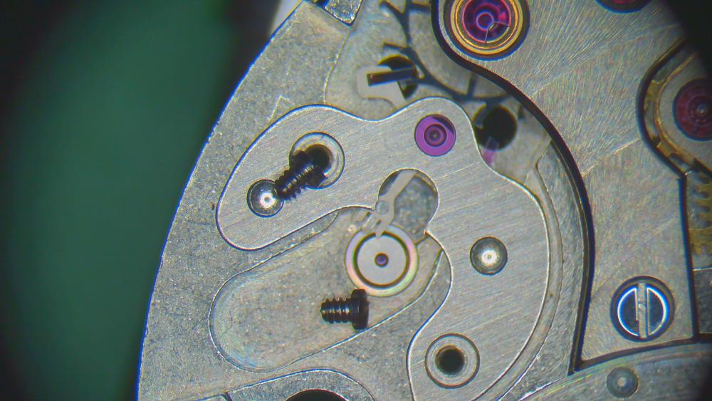
I must admit, this has got me beat. I have no likely explanation why these two screws will not release on a movement which is only 5 years old, in decent condition, with no signs of rust. Sorry to ask, but are you sure you are turning them the right way, i.e. anticlockwise? The only thing I can suggest is to strip as many of the other components as you can from the mainplate and then use a combination of penetrating oil, impacts and heat from a soldering iron to break down the bonding. Unless you are prepared to use it as a manual wind you have nothing to lose. The movement is only good for spares as it is.0 points


.thumb.jpg.cb17a66989f1e796fd4217db2e9ca9df.jpg)