Jump to content

Recommended Posts

Posted

I have some massive wear on the setting wheel post of a citizen 5270 movement. On the other side of the mainplate I don't see any indication that it is a pressed-in post. Could these perhaps be part of the main plate itself? If so, what is the recommended "plan of attack"? Drilling it out and replacing it with a pressed in post? Grateful for any suggestions!


20240701_191006.jpg

20240701_192613.jpg

Posted

That's the intermediate minute wheel and there looks more wear to it than the post.

Can you measure how worn the wheel is?

If it is the post that's worn then I'd consider a collar to resize it.

  • Like 1
  • Thanks 1
Posted
2 hours ago, caseback said:

I have some massive wear on the setting wheel post of a citizen 5270 movement. On the other side of the mainplate I don't see any indication that it is a pressed-in post. Could these perhaps be part of the main plate itself? If so, what is the recommended "plan of attack"? Drilling it out and replacing it with a pressed in post? Grateful for any suggestions!


20240701_191006.jpg

20240701_192613.jpg

Something has been wrong to screw up the meshing with the minute wheel, those teeth are well chewed up.

Post will be part of thd mainplate. 

  • Thanks 1
Posted
1 hour ago, Neverenoughwatches said:

Something has been wrong to screw up the meshing with the minute wheel, those teeth are well chewed up.

Post will be part of thd mainplate. 

Cannon pinion hammered on too tight?

  • Thanks 1
Posted
26 minutes ago, KarlvonKoln said:

Cannon pinion hammered on too tight?

No. Just the opposite. Cannon pinion not pressed all the way down, so the pinion leaves were just glancing off the teeth of the minute wheel.

  • Like 1
  • Thanks 2
Posted
5 hours ago, AndyGSi said:

That's the intermediate minute wheel and there looks more wear to it than the post.

Can you measure how worn the wheel is?

If it is the post that's worn then I'd consider a collar to resize it.

The wheel is made of steel and is ok. The top part of the post is not in contact with the wheel and is ok as well. Just one side of the post is worn. The wheel has been gradually eating up the post, creating more and more play between the wheel and the "not worn" side of the post. That's the play you see. 

Thanks for the advice on the collar.

4 hours ago, Neverenoughwatches said:

Something has been wrong to screw up the meshing with the minute wheel, those teeth are well chewed up.

Post will be part of thd mainplate. 

The intermediate wheel is getting more and more "out of line" by the wear on the post, screwing up the meshing indeed. I already found a replacement minute wheel, but need to fix that post otherwise it will be chewed up again very fast..

2 hours ago, KarlvonKoln said:

Cannon pinion hammered on too tight?

That, or the fact that this watch was worn every day for 50 years without getting any service... 🙂

i agree that the cannon pinion is probably what caused the wear on the post and the minute wheel.


Now finding a way to fix this.. Getting a replacement main plate is an option, but only as a last resort. I would prefer to fix this, if not only for the learning experience..

Posted
5 hours ago, HectorLooi said:

No. Just the opposite. Cannon pinion not pressed all the way down, so the pinion leaves were just glancing off the teeth of the minute wheel.

👍 looks like the cp hasn't been pushed down and riding on top of the minute wheel, possible wear under the cp as well. 

8 hours ago, AndyGSi said:

That's the intermediate minute wheel and there looks more wear to it than the post.

Can you measure how worn the wheel is?

If it is the post that's worn then I'd consider a collar to resize it.

Open up the int. wheel hole to fit ? 

9 hours ago, caseback said:

Drilling it out and replacing it with a pressed in post? Grateful for any suggestions!

You going to need a lathe to center it accurately .

8 minutes ago, Neverenoughwatches said:

Open up the int. wheel hole to fit

This comment has brought a question to mind 🤔

  • Thanks 1
Posted
1 hour ago, Neverenoughwatches said:

You going to need a lathe to center it accurately .

Convention method would need a lathe, a face plate, optical centering scope and drills. 

I would like to hear what @nevenbekriev would do in a case like this.

  • Like 1
  • Thanks 1
Posted

When I repair an issue like this, I center up in a faceplate (with a scope like Hector says), turn the post until it's clean, and friction fit a tube to the remaining post. The tube is usually in steel, but I have done them in beryllium copper as well, either will last 10x longer than the original brass.


Drilling and fitting a new post is tricky at best; this post is  just above where the stem pivot fits, so you either have to drill (bore) quite oversize, fit up, then redrill the hole for the stem, or you end up with a very shallow fit for pressing in the new post.


Using a scope for faceplate centering sounds fancy and expensive, but you just need some sort of scope like 20x or so, with some sort of a cross hair or such in the viewpath, and it can be held any way you find convenient to view the workpiece. When turning the faceplate by hand, any eccentricity is instantly visible, and it's actually very nice to be able to move the scope to line up the cross hair with the perimeter of what you're centering. I have old "analog" scopes I use for this, but I'm sure the plethora of cheap digital scopes offer an easy option.

  • Like 2
  • Thanks 1
Posted
5 hours ago, HectorLooi said:

Convention method would need a lathe, a face plate, optical centering scope and drills. 

I would like to hear what @nevenbekriev would do in a case like this.

I need to see the movement. If there is enough 'meat' under the post to drill a hole and to press new seel post there, this is a piece of cake. Of course, one can do it on the late with face plate. If I have to do it this way, will center by the undamaged part of the post. I don't have scope and never have used one. My Optivisor (#7) glasses  is what I use and this is enough. placing the cutter tip close to the object (the post) and observind the distance between them while rotating the spindle helps to find the needed direction for moving the movement in the face plate.

The easier way is to file the post with dremel and drill the hole by hand, the drill bit in pin wise. Centering  with center drill bit, which donesn't bend and moving the center when turning the wise and pressing in needed direction is possible. The circular traces from mashining the post in the plate are enough to find the center. Another way is to use depthing tool to find the correct distance between posts of the minute and intermediate wheels and the distance between intermediate and the wheel in the rocker when rocker is in setting position and to draw arches, the crossing point will be the center for the post.

For sure the cannon pinion must be checked, such wear is not normal in this place. Is there a calendar on the movement? Setting the calendar and cannon seizing due lack of lubrication may explain this kind of wear.

  • Thanks 2
Posted
4 hours ago, nevenbekriev said:

I need to see the movement. If there is enough 'meat' under the post to drill a hole and to press new seel post there, this is a piece of cake.  

For sure the cannon pinion must be checked, such wear is not normal in this place. Is there a calendar on the movement? Setting the calendar and cannon seizing due lack of lubrication may explain this kind of wear.

Yes, fortunately there seems to be enough "meat" to fit a post. And indeed, it has a calender. The piece belongs to my uncle who proudly told me that he bought it new more than 50 years ago and "it has never needed a service".. I've also found very serious wear in the automatic winding system.

Thanks everyone for the advice!!

I have a 8mm lathe, but no faceplate yet. I'll try to source one, or do it by hand.

Posted

I didn't want to put this watch on the I'll-finish-it-once-I've-got-hold-of-the-right-tool pile while looking for a faceplate, so I've drilled it freehand (Thnx Nev!) using a set of cheap carbide drills and pressed in a steel 0.5mm stud.

It lines up nicely with the cover plate and both wheels turn very smooth. I'm happy. Thanks everyone!

20240707_195106.jpg

20240707_195752.jpg

20240707_195854.jpg

  • Like 3

Join the conversation

You can post now and register later. If you have an account, sign in now to post with your account.
Note: Your post will require moderator approval before it will be visible.

Guest
Reply to this topic...

×   Pasted as rich text.   Restore formatting

  Only 75 emoji are allowed.

×   Your link has been automatically embedded.   Display as a link instead

×   Your previous content has been restored.   Clear editor

×   You cannot paste images directly. Upload or insert images from URL.

  • Recently Browsing

    • No registered users viewing this page.
  • Topics

  • Posts

    • Aw come on Andy, it was just a comparison between spending 30 quid and tackling a tricky piece of work. You appeared to be volunteering,  i volunteer for stuff all the time it gets me into all kinds of trouble.
    • It's not really shown here , but the blade flips over, so it faces the other way. The knob and threaded case holder then pushes the caseback seam into the blade. Once the blade starts to penetrate into it, the lever and blade are lifted , which should hopefully pop the back off. A lot of fashion style cases have very tight seams and need a sharp blade to start separating them.  Don't buy the cheaper plastic versions of this tool, the posts with the pins through for blade holder break easily if the apply extra force to blade. 
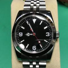
    • You will still be looking for a balance complete I’m afraid, this is the balance staff, balance wheel and hairspring in one package. Hairspring and the balance wheel are matched in the factory. Whilst we can change a balance staff the hairspring and balance wheel stay together.   Tom
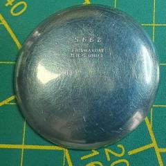
    • The hairspring end has come adrift from the small terminal barrel.  I have tried to remove the taper pin to relocate it, but the task is beyond my skill set, eyes, hands and being in my 70s, probably beyond my life expectancy.  It is not too badly mangled on the end.  On the ebay offer, that really is a bit on the rich side.  I'll keep looking, maybe a good hairspring will turn up with a shot balance staff. As for time spent on knees.  I made up one of these from 3M magnetic tape and a piece of wood.  It works well for magnetic parts. Other things I have suffered with.  I found lubricants so very expensive that I bought some very small syringes and tiny needles.  I just decant a drop into my oiling pots when I start a movement and the remainder keeps really well in the syringes. Finally identifying the correct screw for the part led me to make up the board in the final pic.   Thanks for the info. Kind regards   Chris  
    • Yes that's the type @watchweasol is referring too but I don't like them as you don't get any feel to what's happening.
×
×
  • Create New...