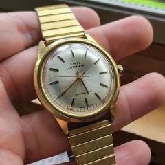
Jump to content

Recommended Posts

Posted

Picked up a lot of watches from eBay at the beginning of last year and finally got around to looking at this unique movement. During disassembly found the stamp for FHF 65-4 and began my search down the rabbit hole for this movement. I did not find much info and realized I wanted to revive this interesting movement. I found a small list of parts that were missing or broken. Missing winding pinion, Casing clamp and screw, and 3 screws to assemble the osculating mass. The pivot on the third wheel was broken, the hairspring and the regulating pin were bent.

I think there is still room to improve the shape but for now it is good enough and I wanted to rebuild the movement to see the current status of the movement and adjust it if needed. I did a check of the rest of the gears and they rotated smoothly so I am hopeful that it is salvageable. I have the third wheel and winding pinion ordered.

20240720_204900.thumb.jpg.27eb8c4e4520a400921145e1488d32db.jpg

20240722_182240.thumb.jpg.8025a32b6e7471fe6328f9df42141686.jpg

20240722_182606.thumb.jpg.d6d9ed846b3d25f1fc7e8315ad909307.jpg

I compared my movement to a couple of videos online and noted that my oscillating mass was missing its bearing balls and so I took some measurements and created a 3D model to see what size was required. From my model it shows that a standard 0.5mm bearing ball would fit. One concern I have is that I cannot tell if there should be a spacer in between the bearing balls to make sure they are equally spaced. Before I order the bearing balls I want to make sure the movement runs well.

20240722_181134.thumb.jpg.82a2e075e125ee1787ed0c00281af747.jpg

20240722_180953.thumb.jpg.892be6050fabafaafe98d9012b39e6a8.jpg

20240722_181131.thumb.jpg.55f5cb7163110a6a671d5e89c6f15f25.jpg

20240720_181600.thumb.jpg.0dca30ef9c0c80a892a8b057dc75501f.jpg

20240720_181629.thumb.jpg.ce1955963bfe161b7ef9c585e371e2e9.jpg

70936eb27639b7ec3f21a383dc1fa405.thumb.png.a7cb59bbbad949cce8b9dd4901e2598d.png

I found this movement online and see the bearing balls equally spaced but cannot tell if there is a spacer.

519DD048-ED1B-41C3-A1A5-E6E0B9806F30.jpeg.e5d2f3336cbbe91375c4b1f28cb1df8e.jpeg

The dial has great patina but the text is fading and should read "Waltham / 17 Jewels" up top and "Self Winding / Incabloc".  Is reprinting the text ever an option?

20240721_111923.thumb.jpg.128390c4aea4e63e2814d89f1bab19b2.jpg

But the watch is missing hands so I was looking around and see what was original to the watch. I came across and ad from 1960 and an example. The case back has a 1962 engraving, so the timelines match up.  I'm currently looking for a set but not much luck on eBay. I am also hesitant due to the chance of radium hands. I like the red arrow but I also like the look of advertisement with just the tip of the seconds hand painted red.

0d010d1c71aa59d747130d46ee672faf.png.8e1a295fc5de2cfc370b848f749b8b66.png5a925312595ecfa454ec0ab2112389f3.thumb.jpg.79b4b27c950774bae0f0634ad9954f17.jpg

I have a couple pictures of the dial side of the movement but its not as unique as the back.

Thanks!

Posted

Interesting movement!

From a quick bit of research, some versions apparently had jewels as the bearing balls for the rotor, so such as a 30+ or even 60+ jewel movement !!


There is a site here that has the parts documents images, if they help? 

Select the image thumbnail then right click & save image in the large window - they are full pages, very clear.

https://www.joseph-watches.com/all-products/fontainmelon-fhf-65-individual-parts-1950s/


Posted

I used those pictures to determine which parts were missing and to cross-check some eBay listings that were in Italian.

  • Like 1
Posted (edited)

Thanks, that's a great resource. I didn't realize Cousins had such a detailed list of parts available. I will absolutely use that in the future.

Unfortunately, of the parts I am still missing they are not on the list. My plan was to get an assortment of casing clamps and screws to round out the parts needed. If I ever get the tools and time I would try and finish them to match.

Have you had luck with 1 casing clamp being enough to secure the movement? There are provisions for 2 casing clamps, so I want to populate them both.

21 minutes ago, AndyGSi said:

Parts are available through cousins.

https://www.cousinsuk.com/category/filter/fhf-movement-parts

Edit

Have you see this of the Rotor parts and showing them as 0.5mm bearing?

image.thumb.png.622c309fbf0261f9cd525aa8c3e57ea0.png

https://omegaforums.net/threads/on-my-bench-waltham-automatic-problem-child.148695/

Great photo!

So my suspicions were right there is a spacer. Seems like my model was the right size and landed at the same 0.5mm bearing balls. Not having the spacer will cause an issue with the bearing balls bunching up. Hmm, I will have to think how I will space them. Not sure I will be able to find one of those spacers.


Also interesting that the third wheel pivots from that post was also broken. I wonder if there is something in the design that makes the third wheel more likely to break?

Edited by AdamT
Posted

Yeah, I am looking to pick up those clamps from cousins. Spareparts-watches came up in my search but no luck with the parts. Also couldn't find the parts in the Jules Borel shop.

I reached out to the person to who repaired the other watch from the Omega website, to see if they still had the donor watch.


Posted

Oh sorry, I already have the winding pinion and third wheel on order. I think the only thing would be parts of the oscillating mass. I am missing the spacer for the bearing balls.

Posted

So is it just the middle piece from the photo I posted above that you're missing that spaces the bearings?

I may be able to get my hands on a Sandoz 333 and see if it can be copied.

Posted
1 hour ago, AdamT said:

I am missing the spacer for the bearing balls.

As long as they are well lubricated, you should be OK just almost filling the race circumference. Leave a small gap, say a millimetre or two, then space the rest out a bit.

Once they distribute themselves in use, they should set their own spacing. A lot of simple bearings such as in bicycles are built like that.


Posted
45 minutes ago, rjenkinsgb said:

As long as they are well lubricated, you should be OK just almost filling the race circumference. Leave a small gap, say a millimetre or two, then space the rest out a bit.

Once they distribute themselves in use, they should set their own spacing. A lot of simple bearings such as in bicycles are built like that.


The problem here is the channel they sit in is wider than the bearing so they would just float about.

Also the spacer allows the screw to be tightened down but still leave space for the bearings to rotate.

You may get away with the spacer as a simple disc without all the notches for the bearings to sit in.

Posted
4 hours ago, rjenkinsgb said:

As long as they are well lubricated, you should be OK just almost filling the race circumference. Leave a small gap, say a millimetre or two, then space the rest out a bit.

Once they distribute themselves in use, they should set their own spacing. A lot of simple bearings such as in bicycles are built like that.


Cannot hurt to try.

4 hours ago, AndyGSi said:

The problem here is the channel they sit in is wider than the bearing so they would just float about.

Also the spacer allows the screw to be tightened down but still leave space for the bearings to rotate.

You may get away with the spacer as a simple disc without all the notches for the bearings to sit in.

I am not sure if the spacer is used to set the height of races. It all depends on the thickness of the spacer, there is a .20mm gap between the 2 plates of the races. I have bearing balls on order so I can test it out in a week or 2.

Posted
9 hours ago, AndyGSi said:

Also the spacer allows the screw to be tightened down but still leave space for the bearings to rotate.

The cage in a (properly designed) ballrace is never designed to touch anything other than balls, and does not apply any force to those - if it did, you would be running on direct friction, making the ball system pointless?

(Remember that the balls move around their groove at half the rate of the inner race rotation; anything fixed to either race would lock the bearing).

This is an extract I found, apparently from the original patent; the inner race is split in to two "layers", so the first has to go in place, then the balls added, then the second inner race part holds everything together. That does not show a cage, though it looks like just twelve balls in this diagram? Other movements I've found may have 40, or 72.

Rotor_Bearing.thumb.jpg.a9bb85dcb51bcdea69806296e8423f36.jpg


Posted
8 hours ago, rjenkinsgb said:

The cage in a (properly designed) ballrace is never designed to touch anything other than balls, and does not apply any force to those - if it did, you would be running on direct friction, making the ball system pointless?

(Remember that the balls move around their groove at half the rate of the inner race rotation; anything fixed to either race would lock the bearing).

This is an extract I found, apparently from the original patent; the inner race is split in to two "layers", so the first has to go in place, then the balls added, then the second inner race part holds everything together. That does not show a cage, though it looks like just twelve balls in this diagram? Other movements I've found may have 40, or 72.

Rotor_Bearing.thumb.jpg.a9bb85dcb51bcdea69806296e8423f36.jpg


Wow, that patent is impressive. Where did you look to find that?

My races look a little different from the patent. That looks like there is no space between the bearing balls and the bottom of  race where as mine has space and could accommodate a spacer.  There is a shoulder that has a thickness of .20mm.

20240724_114730.thumb.jpg.721b43af6cb20a887a754ba466171e84.jpg


7 hours ago, AndyGSi said:

This has 72 bearings and if you look at the exploded photo above and part
copied below there's a spacer with notches to position each on these bearing.


image.png

As long as every bearing ball is touching the races they should not slip in the races. My guess that if there is only 12 it is unlikely that the balls would touch each other and only once you increase up to 72 does the spacer be required to keep it efficient.

I have made contact with the watchmaker from the Omega forum and he said he still has the spare so I should be able to purchase the spacer and I can do some testing and see how the mass preforms with and with out the spacer with various amounts of ball bearings. I have only ordered 50 bearing balls so it may fall slightly short of the 72 number.

I think in variations of this movement, they used ruby bearings balls. That would quite the cost but would be very beautiful to watch.

  • Like 1

Join the conversation

You can post now and register later. If you have an account, sign in now to post with your account.
Note: Your post will require moderator approval before it will be visible.

Guest
Reply to this topic...

×   Pasted as rich text.   Restore formatting

  Only 75 emoji are allowed.

×   Your link has been automatically embedded.   Display as a link instead

×   Your previous content has been restored.   Clear editor

×   You cannot paste images directly. Upload or insert images from URL.

  • Recently Browsing

    • No registered users viewing this page.
  • Topics

  • Posts

    • I’ve been playing with a NH35 movement that which has the classic Etachron regulation system and a few balance assemblies as practice. What I’m trying to do is get comfortable with the effect both the stud and regulator pin positions have on rate and positional error. When I install a new balance assembly I install it with the assembly in place  on the cock and cock is attached to base plate. I use the back of the tweezers to push the stud into place and feel the click. However, I noticed that the angle of the stud can be adjusted and what I also noticed is that some movements have the stud carrier arm bent down a little and that changes the angle of the hairspring leaving the stud. This angle effects how the spring goes through the regulator pins and also the spacing of the coils opposite the stud. What I thought I was supposed to do is set the regulator block in the middle of the curve, open the pins, and use the stud angle to center the spring.  Then the stud is set.  Now on all the new NH movements I have seen the angle of the regulator block is about 60 degrees counter clockwise from full open. I watched a video where the author used the regulator pin adjust to adjust rate and position error. When I close down the pins I do notice that the rate increases but also the amplitude drops, the coil spacing changes and hairspring appears slight straighter between the stud and the regulator block. If I open the pins the amplitude comes back, the spring breathes a bit more between the stud and the regulator block and the rate slows.  So, a long post I know but I would really appreciate any advice on how to correctly adjust the etachron system for rate, amplitude and positional error.   
    • Aw come on Andy, it was just a comparison between spending 30 quid and tackling a tricky piece of work. You appeared to be volunteering,  i volunteer for stuff all the time it gets me into all kinds of trouble.
    • It's not really shown here , but the blade flips over, so it faces the other way. The knob and threaded case holder then pushes the caseback seam into the blade. Once the blade starts to penetrate into it, the lever and blade are lifted , which should hopefully pop the back off. A lot of fashion style cases have very tight seams and need a sharp blade to start separating them.  Don't buy the cheaper plastic versions of this tool, the posts with the pins through for blade holder break easily if the apply extra force to blade. 
    • You will still be looking for a balance complete I’m afraid, this is the balance staff, balance wheel and hairspring in one package. Hairspring and the balance wheel are matched in the factory. Whilst we can change a balance staff the hairspring and balance wheel stay together.   Tom
    • The hairspring end has come adrift from the small terminal barrel.  I have tried to remove the taper pin to relocate it, but the task is beyond my skill set, eyes, hands and being in my 70s, probably beyond my life expectancy.  It is not too badly mangled on the end.  On the ebay offer, that really is a bit on the rich side.  I'll keep looking, maybe a good hairspring will turn up with a shot balance staff. As for time spent on knees.  I made up one of these from 3M magnetic tape and a piece of wood.  It works well for magnetic parts. Other things I have suffered with.  I found lubricants so very expensive that I bought some very small syringes and tiny needles.  I just decant a drop into my oiling pots when I start a movement and the remainder keeps really well in the syringes. Finally identifying the correct screw for the part led me to make up the board in the final pic.   Thanks for the info. Kind regards   Chris  
×
×
  • Create New...