
Advice Requested: Tempermental Landeron 48 Chronograph
-
Recently Browsing
- No registered users viewing this page.
-
Topics
-
-
Posts
-

By HectorLooi · Posted
I've seen many quartz watches with this kind of foggy crystals. It usually happens when the battery leaks. It's probably the electrolyte vapor. Remove the crystal by sticking a piece of double sided foam tape to the crystal and to the surface of your workbench. Then pull straight up on the watch straps. The crystal should pop off. There is an actual tool on AliExpress for this job, in case you find this method too "rustic". The fog should wash of easily. But I'm more concerned about the rest of the watch, as the electrolyte vapor is all over everything and it's very corrosive. I would do a full disassembly and rinse everything in a diluted acid. I use phosphoric acid but vinegar works fine too. Dry thoroughly, then do a full service. Watch tool is used to open the watch glass and open the watch cover https://a.aliexpress.com/_msI3lhh -
-
 I have been looking for this exact thread for days now! I love watchrepairtalk.com!! 🥰 Thank you, thank all of you!
 -

-
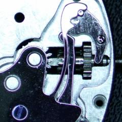
 The white circle shows the expected radius of the „golden curve“. The red arrow points to where the hairspring is kinked most likely.
-


Recommended Posts
Join the conversation
You can post now and register later. If you have an account, sign in now to post with your account.
Note: Your post will require moderator approval before it will be visible.