Jump to content

Recommended Posts

Posted (edited)

I have the movement almost back together. Just one end stone for the balance and the automatic weight to install.

A quick test of the balance to see if I noticed any improvement and the results looked the same. However something caught my eye…

IMG_1345.thumb.jpeg.a98defd2e3b010d897c0cf2b2a7ad0d0.jpeg
 

This is actually a reenactment as I’d already fixed it before I got a picture and I think it was even further to the negative side. But I thought I’d take a photo as threads are way better with pics.

So I put a small wind in to the movement, got the balance spinning and moved the regulator to the middle position. An immediate improvement in the amplitude that was visible to the eye.

So it looks like my cleaning methods were a bit heavy handed around the balance adjuster. Not to be repeated as I have some baskets on the way which will fix this.

Hoping I’ll be back to normal once I have it all together and on the timegrapher.

Edited by neevo
Posted

Sorry, but what are You trying to do without the jewel setting of the balance?

Seems that the hairspring is a little bent, it will need rectifying. Moving the regulator in reasonable limits should not change the amplitude.

I just looked at the hairspring picture in the page1.

You will have to do some work with the hairspring.

IMG_1343.jpeg.9e00de06620a216c0b4cfdc3a4c2679b.thumb.jpeg.6e153ab77296ff83fcd6c4e5651d46d3.jpegIMG_1343.jpeg.9e00de06620a216c0b4cfdc3a4c2679b.thumb.jpeg.6e153ab77296ff83fcd6c4e5651d46d3.jpeg

Two problems are seen  aside from the fact that the spring is not centered. The white circle shows that two pairs of coils are stacked together. The yellow arrows at the bottom show that the spring is touching the stud.

Now, the stack coils show the spring is sticky or magnetized. As the spring can not be magnetized (it is made of material that don't magnetize), magnetized can be the regulator and stud holder. This is not very probable thou. Did You check if the demagnetizer actually works? Most probably, the spring is sticky. This means that is is not well cleaned or actually contaminated by the process of cleaning. But, what is seen from the picture is that making the spring unstick will not improve it's position (the two problems)

I have placed two red circles. The balance arm covers the spring there so it is not seen. I have drawn it with yellow just to show how it looks. This red circles show where You have to manipulate the spring. You have to open the angle with the bigger circle, this will make the spring concentric and get away from the stud. This will get clear in the process, but may be the angle with the smaller circle will need a little opening too. The idea is the distances shown with yellow arrows to become equal and in the same time the spring to stay concentric. Yes, this is like etachron stud carrier/regulator that can be moved, but i will advice at this point to touch the spring only.

  • Like 2
Posted

My demagnetiser hasn’t arrived yet, but when it does, let me demag the movement and I will take another picture of the balance spring for some advice.

Appreciate everyone’s help.

Posted (edited)

@JohnR725 the demagnetiser came in and here it is with the lid off. Nothing too crazy but looks like a transformer to generate the electrical field, a momentary switch and some electronics that I assume is doing the switching for the collapsing electrical field.

IMG_1366.thumb.jpeg.6cb1d64d78c2ec88f50c340badef2ecc.jpeg

IMG_1365.thumb.jpeg.2333dd9296cb138cde110f61919fa3bb.jpeg
 

I put my tweezers on it to see if it worked as they cause everything they touch to stick to them. A couple of things to note:

1. it moves the tweezers as it activates. Clearly the crosshairs are there for a reason to make sure the object is centralised.

2. I moved the tweezers 90 degrees in between button presses. No idea why I’ve just seen someone do it on YouTube

3. it completely removed all magnetism. Result!

IMG_1367.jpeg

Edited by neevo
  • Like 3
Posted

Unfortunately this device is not electrically safe and could not be sold in Europe (certainly Australia, too) legally. However no one cares.

It has no protecting earth connection while at the same time has a touchable metal part  - that you will touch 100% each time, the metal pusher!

Frank


  • Like 1
Posted
54 minutes ago, praezis said:

Unfortunately this device is not electrically safe and could not be sold in Europe (certainly Australia, too) legally. However no one cares.

It has no protecting earth connection while at the same time has a touchable metal part  - that you will touch 100% each time, the metal pusher!

Frank


Looks to me like the pusher is low voltage so isn't a problem.

Posted
6 minutes ago, praezis said:

Do you know the schematic?
But it doesn‘t matter anyways. It is unsafe.

Frank

You can see the input wires to a transformer and then full wave rectified so at low voltage and DC it's perfectly safe.

Posted

I am afraid you miss the problem totally🤔

Beyond, these devices use rectified mains voltage, which is doubled then (~600V). 
And a transformer is visible nowhere.

Frank

Posted
58 minutes ago, praezis said:

I am afraid you miss the problem totally🤔

Beyond, these devices use rectified mains voltage, which is doubled then (~600V). 
And a transformer is visible nowhere.

Frank

Sorry Frank, I don’t understand you here. There is a honking big transformer right slap bang in the middle of the unit.


Tom

Posted
25 minutes ago, praezis said:

Tom,
that is no transformer but the coil for demagnetizing. Note there are only 2 wires to it.

Frank

Looking further into the photo I suspect that they have just wired the primary of the transformer to be the magnetic coil. Looking at the remaining components there does look to be a rectifier cct of 4 diodes. Maybe the potted box at the bottom right corner is a capacitor (hefty one).  This would lead me to think this is some form of capacitive discharge cct. Not at all sure if there is any low voltage side with potentially 240V rectified going to the switch.


Tom

p.s. It’s a very long time since I have used my electronics education, last was 1985 on pump control systems mainly, surface to air missile and radar systems before that.

Posted

Frank- if one were to make this device at least safe-er, would adding a 3 wire cable and grounding at least the switch be worth the effort?


Thinking back, all the ancient demagnetizers I've had including my Greiner Magnomatic are ungrounded, but that one doesn't have any exposed metal.

Posted (edited)

I expected this would be a transformer with the rectifier diodes on it's output.

Be interested to know the voltage on the bottom of these diodes.

image.png.2d8cc5529b7c368501788c0e82570a25.png

Would also be interested to know what voltage this Cap & Relay are?

image.png.27cc5aa6e0b4cfce9b73c23bb1a32af6.png

Edit

Just realised from the number on the side of what I thought was a transformer is actually a polyester cap

Edited by AndyGSi
Posted
4 hours ago, praezis said:

Unfortunately this device is not electrically safe and could not be sold in Europe (certainly Australia, too) legally. However no one cares.

It has no protecting earth connection while at the same time has a touchable metal part  - that you will touch 100% each time, the metal pusher!

Frank


The Elma Antimag doesn't seem to be earthed either.

The metal switch problem can be easily rectified by using a all plastic switch.

Posted (edited)

Stewart,
simplest measure is to change the push switch against a full plastic one, of course qualified for safe handling voltage and current that is switched. Then the 2 wire mains cord would be ok.

Hector,
it doesn‘t have to as there are no touchable metal parts. 
Just recommended the same. But the chinese unit is released to the public still not safe.

Frank

Edited by praezis
Posted
12 hours ago, neevo said:

@JohnR725 the demagnetiser came in and here it is with the lid off. Nothing too crazy but looks like a transformer to generate the electrical field, a momentary switch and some electronics that I assume is doing the switching for the collapsing electrical field.

6 hours ago, praezis said:

Do you know the schematic?
But it doesn‘t matter anyways. It is unsafe.

2 hours ago, HectorLooi said:

The Elma Antimag doesn't seem to be earthed either.

what I was curious about is how closely does it resembled the Elma. I have one lurking around here is supposed to be fixing it just didn't quite get around to it. Then I know I posted the pictures on the discussion groups there lurking someplace. Then occasionally thinking about it yes it is a different circuit board because there is a rather live sizable he physically large motor starting capacitor that they were using the charge up to discharge through the coil.

Basically with any of these units you want to keep your fingers away from things. They usually charge up a capacitor with depending upon where you discharge and lethal voltages and then discharge it through the coil C as well be careful not to put your fingers in a place where it could go through you. Similar to the old photo flash circuits found in cameras you can charge up a really nasty voltage and those capacitors before it fires the flash tube. Or it's really amazing what you do with a couple of tiny batteries and a capacitor.


  • Like 2
Posted
42 minutes ago, RichardHarris123 said:

My knowledge of EE is limited, so I don't know whom is correct but instead of changing the switch to a plastic one, you could just push it with peg wood instead? 

I suppose you could get a meter and measure the voltage is on the switch itself as to whether it's a problem or not. Then a course you have to accept the fact that there's always going to be a catastrophic failure and you'd still have lethal voltages everywhere conceivably. Or you get creative and move the switch farther back into the box and put a plastic button to push so they basically are pegged would but isolate the switch from the outside if that was your concern. But I suspect if you look at a lot of the demagnetize and devices in the past and are worried about catastrophic failures well you probably shouldn't One for the most part. Through there are some really nice ones stuff is isolated were done much nicer but usually at a much much nicer price. Rall a price nice for the manufacturer not for the buyer as they tend to be expensive.

Posted
1 hour ago, JohnR725 said:

catastrophic failure and you'd still have lethal voltages everywhere conceivably

The most likely dangerous fault by far is one of the mains wires coming loose inside the unit and touching the chassis of the button. There's no other metal on the outside of this unit as far as I can see. I'd consider replacing the mains wire with one that carries ground and grounding the button chassis.

At least it's not as bad as the one I have... They sure didn't waste any money here.

IMG_7371.jpg

Posted
7 minutes ago, HectorLooi said:

They used a metal oxide resistor instead of a carbon one.

Just measured the resistor to 891k. This is supposed to be a 5 % 1 M so it's out of spec. I'm guessing from the reject bin. Maybe the blue paint is just decorative, not indicative of quality...

Posted
10 hours ago, HectorLooi said:

Yes they did. They used a metal oxide resistor instead of a carbon one.

I will say for sure that the resistor and the LED are not needed for the function of the device, so they could  be saved in manufacture.

Posted
10 hours ago, AndyGSi said:

I suppose the first question should have been is it even a metal button?

I think everyone has assumed it is Andy unless they know for sure, but it does look like steel, the casing at least. Does plastic come in a steel/chrome colour 🤔.......👍.......😅

Screenshot_20241217-082441_Samsung Internet.jpg

Join the conversation

You can post now and register later. If you have an account, sign in now to post with your account.
Note: Your post will require moderator approval before it will be visible.

Guest
Reply to this topic...

×   Pasted as rich text.   Restore formatting

  Only 75 emoji are allowed.

×   Your link has been automatically embedded.   Display as a link instead

×   Your previous content has been restored.   Clear editor

×   You cannot paste images directly. Upload or insert images from URL.


  • Recently Browsing

    • No registered users viewing this page.
  • Topics

  • Posts

    • This is the old/first(?) way for making a mainspring for an automatic. "Evolution-wise" it is an logical first step forward from a standard spring. Usually these are indeed replaced with a new spring with an integrated/fixed bridle. Lubrication as you would do with any automatic.
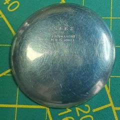
    • I'm working on a Schild AS 1250 (a 'bumper' automatic) and it's the first time I've seen a mainspring like this. It has what looks like a regular manual-wind mainspring with a 'hook' at its outer extremity. On a manual-wind watch that 'hook' would engage with a 'hook' in the barrel wall to prevent it from rotating. However, the AS 1250's mainspring does not engage directly with the barrel but rather with a 'sliding bridle' that sits between the mainspring and the barrel wall, and evidently facilitates the slip necessary in an automatic. I'm not sure what advantage this two-piece configuration provides, but it highlights a gap (one of many) in my horological knowledge. I'm not sure if 'hook' is the correct term as used above, but please see photo below to see what I mean. Therefore, two questions please. 1. What is the proper way to lubricate a barrel from an automatic watch with a sliding bridle? My guess is the same as any automatic ms/barrel (e.g, a few dabs of braking grease on the interior barrel wall). What do the experts say? 2. I purchased a Generale Ressorts GR3472X mainspring, made for the AS 1250. It looks like the bridle is included and I don't need to salvage and re-use the old one. Is this a safe assumption? Thanks for the advice. If you have any other wisdom you'd like to share about separate sliding mainspring bridles, I would be very interested. Cheers!
    • Thank you Hector. You too matey 😊
    • Bless you, Mark. May you live long and prosper!
    • That’s a nice idea, But i’m committed to providing this site as a gift to the watch repair community as my thank you for my incredible life i’ve had in this business. Ive done well and unless my financial circumstances change then i’m more than happy to foot the bill. If circumstances do change then be assured that I will make an appeal. For now, I’m comfortable with the way things are and I am extremely delighted to remove Google Ads from this site and to stop Patreon, it feels like a major step forward 🙂 Sorry, I missed your reply, I got blinded by another poster in this thread. Yes - I can confirm that I have always seen WRT as a not-for-profit website, and therefore - not a business as such. I’m lucky and have done well in my life due to a decision made in my teens to start a watch repairing apprenticeship which has sustained myself and my family for many years now. Consider this my small way of paying it forward. Ive been committed to keeping the site alive on a technical and financial level for over 10 years now and I have zero plans to change that. Thank you for your kind words by the way. And as for your wish - nobody can control what happens in life, if something happens to me I have things in place with my family but I’m just not comfortable talking about my personal business - I wish a certain person would respect that, but i’ve calmed down now - i’m only human 😄  
×
×
  • Create New...