Jump to content

Recommended Posts

Posted

I’ve been playing with a NH35 movement that which has the classic 
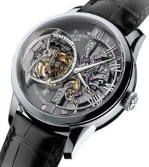
Etachron regulation system and a few balance assemblies as practice. What I’m trying to do is get comfortable with the effect both the stud and regulator pin positions have on rate and positional error.

When I install a new balance assembly I install it with the assembly in place  on the cock and cock is attached to base plate. I use the back of the tweezers to push the stud into place and feel the click.

However, I noticed that the angle of the stud can be adjusted and what I also noticed is that some movements have the stud carrier arm bent down a little and that changes the angle of the hairspring leaving the stud. This angle effects how the spring goes through the regulator pins and also the spacing of the coils opposite the stud. What I thought I was supposed to do is set the regulator block in the middle of the curve, open the pins, and use the stud angle to center the spring.  Then the stud is set. 

Now on all the new NH movements I have seen the angle of the regulator block is about 60 degrees counter clockwise from full open. I watched a video where the author used the regulator pin adjust to adjust rate and position error. When I close down the pins I do notice that the rate increases but also the amplitude drops, the coil spacing changes and hairspring appears slight straighter between the stud and the regulator block. If I open the pins the amplitude comes back, the spring breathes a bit more between the stud and the regulator block and the rate slows. 

So, a long post I know but I would really appreciate any advice on how to correctly adjust the etachron system for rate, amplitude and positional error. 


IMG_4100.jpeg

Posted (edited)

I’ve watched every video I can find on YouTube. Some of the info is contradictory and none mention  the effect on amplitude or spring coil spacing which I observed. I was hoping someone here is a Seiko expert and knows these inside out. 


Edited by BobG
Posted

The video I linked above does mention the spacing of the hairspring coils, and the importance of the regulator being able to move through its full range without distorting the hairspring - the terminal curve of the hairspring must be concentric with the regulator pins throughout the regulator’s range. 

If you meticulously follow every step in this video, the regulator system should behave as intended, regardless of the brand of the movement. 

Best Regards,

Mark

  • Like 1
Posted (edited)

Alex mentions the coils below the stud should remain the same as you move the regulator block along the terminal curve. 
Mine do that. What he doesn’t discuss and is used in the other video is how the regulator block is used to adjust rate and positional error.  He also doesn’t mention how opening and closing the pins could and in my case does, alter amplitude 
In Alex’s video once he sets the stud he never adjusts the regulator pins yet every new movement I get have the pins signing closed. 

Edited by BobG
Posted

Some photos of the angles you are talking about, and the changes you are seeing to coil spacing etc. would be really useful.

Part of your problem could be that you are closing the pins too far and pinching the hairspring. Adjusting the pin separation should not affect amplitude. Nor should it change the coil separation.

  • Like 2
Posted

Did you watch the whole video?

Once Alex has set the stud, he first corrects the best error, then checks that the hairspring coils are breathing concentrically, then turns the stud to centre the hairspring between the open regulator pins. 

He then checks that the regulator can traverse the terminal curve without disturbing the hairspring. A correction is needed, which he performs. 

He then reinstalls the balance and re-centres the hairspring between the regulator pins, and verifies that the regulator traverses the terminal curve without disturbing the hairspring. 

Finally, he demonstrates how to close the gap between pins. 

He then recaps the whole process, fleshing out more detail.

If you follow this process, you have correctly set up the regulator pins, and are ready to set the rate of the watch. 

If you are interested in learning more about the effects of the regulator pin spacing on positional rates etc, you can read any literature regarding regulator pins.

The etachron system makes adjusting beat, centering the hairspring between the regulator pins and adjusting the gap between the pins very convenient, but the same rules that apply to old style regulator pins apply to the etachron system. 

This video explains the basics


I hope that helps,

Mark

  • Like 2
  • Thanks 1
Posted

I posted a link to another video where he takes it a step further and uses the pins to set and adjust rate as well as positional error. 
Alex doesn’t manipulate the stud angle after he pushes it in but I find it makes a difference in the spring concentricity and bend.  Amex also doesn’t use the pin manipulation to adjust positional discrepancies. 
 

IMG_4100.jpeg

Join the conversation

You can post now and register later. If you have an account, sign in now to post with your account.
Note: Your post will require moderator approval before it will be visible.

Guest
Reply to this topic...

×   Pasted as rich text.   Restore formatting

  Only 75 emoji are allowed.

×   Your link has been automatically embedded.   Display as a link instead

×   Your previous content has been restored.   Clear editor

×   You cannot paste images directly. Upload or insert images from URL.

  • Recently Browsing

  • Topics

  • Posts

    • Hi folks, I'm doing some homework on getting a watchmaker's lathe, and it's clear I have a lot to learn. But I know one goal: I want to be able to fabricate wheels, which would require an indexing capability. I know how to use large lathes- like, giant metal lathes- but my experience is a few decades old now (but you never forget the smell of the metal cutting oil). So I'm looking to learn anew, and have a goal to get to a point where I can fabricate some basic watch parts. I also have no specific timeframe and want to do this right, so I'll be patient and learn what I need to before spending the money. I know I'm not going to get anything for a pittance, but I'm also not really able to put together the scratch for a $5-$10k lathe. What's out there for a hobbyist that can either handle some fabrication out of the box or can be relatively easily made to do so? Thanks!  
    • Hello and welcome to the WRT forum.   This usually points to broken balance pivot.  Though a watch in need of clean & lube can do the same. Easiest diag would be to  see if balance pivot doesn't stay in hole jewel of the setting, when you lift one side of balance rim with an oiler or gently with pair of tweezers. Another would be to detach balance complete from the cock and take a look at pivot under high maginfication.  Regs 
    • Ahhh, yes.  I hadn’t thought of that.  I’ve serviced quite a few of these and the first time I didn’t realise it was a ships strike pattern!  Ha ha, confused me totally until I realised.
    • Hello and welcome from Leeds, England. 
    • Hi Mike, I did, thanks. Found this clip that was really helpful:   It says Seth Thomas but it's actually the same Hermle I've been working on. I'd had it working correctly all along but hadn't noticed that the lever with the sprung end stops the hammer a bit short of the bell on the second ding at the end of the half-past sequence. If only I'd put the bell on when testing, rather than just looking at the hammer, my ears would have told me it was working,  even if my eyes didn't!  
×
×
  • Create New...