Jump to content

Chinese Timegraphers


Recommended Posts

As @xyzzy suggested, I just soldered a lead to SPK (GND) and R3 (tricky!) and managed to feed it 5V from my power supply.

The voltage at C1 is still about 0.3V. 

I put the meter in one of the lines to read to current, which appeared zero, or close to it (I need to solder the connectors on my test leads, they are cheap rubbish, so I was getting fluctuating results).

It may never work, but at least I'm getting some enjoyment and learning something from the testing 😃


26 minutes ago, VWatchie said:

Having read some of the posts in this thread I am thinking that I refuse to become an electronics engineer to be able to repair mechanical watches. Nevertheless, I'm utterly impressed by the effort. Good luck!

I am an engineer (aero) but feel totally stupid and clueless chasing electrons around ! 

  • Like 1
Link to comment
Share on other sites

Could someone with knowledge please comment the finding that REGV is 0,64V on the faulty board instead of the correct 3,3V?
Is that a faulty CM108 (internal 3,3V source) or could it be an external short circuit?

Edited by Kalanag
Link to comment
Share on other sites

23 minutes ago, Kalanag said:

Could someone with knowledge please comment the finding that REGV is 0,64V on the faulty board instead of the correct 3,3V?
Is that a faulty CM108 (internal 3,3V source) or could it be an external short circuit?

REGV is generated by an internal 5V to 3,3V regulator.  Either, the regulator is bad, or there is a load on the regulator that is preventing it from giving a proper output.  REGV goes to a capacitor (unlikely the problem) and to a 1,5K resistor back to the usb plug.  If you have tested both boards with the same USB cable, then the USB cable is not a good suspect.  You could remove the 1,5K resistor and take the measurement again.

  • Like 1
Link to comment
Share on other sites

Here is the reference circuit of the C108. As we know, the internal 3,3V source of the chip delivers just 0,6V. If there is an external short circuit it only can be the capacitor C5 (which is C1 on the board). @mikepilk measured 0,6V at pin 3 of the USB socket which indicates that there is no short on the USB side. C1 can be tested without desoldering.

Edit: @LittleWatchShopwas faster…

6430041A-1F44-464F-9300-881FE774CB8F.jpeg

Edited by Kalanag
Link to comment
Share on other sites

1 minute ago, Kalanag said:

Here is the reference circuit of the C108. As we know, the internal 3,3V source of the chip delivers just 0,6V. If there is an external short circuit it only can be the capacitor C5 (which is C1 on the board). @mikepilk measured 0,6V at pin 3 of the USB socket which indicates that there is no short on the USB side. C1 can be tested without desoldering.

6430041A-1F44-464F-9300-881FE774CB8F.jpeg

I have not been following this thread closely...just looked at your previous post.  So, I did not have all of the other measurement data. 

I doubt the capacitor is shorted.  Extremely rare.  Possibly a solder bridge, but you would likely measure something closer to 0V


Link to comment
Share on other sites

4 minutes ago, LittleWatchShop said:

…I doubt the capacitor is shorted.  Extremely rare.  Possibly a solder bridge, but you would likely measure something closer to 0V

You are right! But if the capacitor is o.k. the C108 is shot 😞

Edited by Kalanag
Link to comment
Share on other sites

Yes! It looks good!

You can test the capacitor with the continuity tester („beep“) of your multimeter by applying the probes to both ends of C1 and listening to a very short beep. If nothing is heard reverse the polarity of the probes and try again. The board must not be connected to the USB cable. 

Another option is the capacity test function of your multimeter. It can be used without desoldering the capacitor.

Edited by Kalanag
Link to comment
Share on other sites

I tried the capacitor testing with my board. Both methods work!

Method 1: The „beep“ is very short so you have to listen carefully.

Method 2: With the black probe at the grounded side and the red probe at the IC side of the capacitor the reading is 3,8 microfarad.

Link to comment
Share on other sites

11 hours ago, mikepilk said:

I do have a DC power supply I bought for plating. I need to read the instructions (so I don't blow it up) but I think I can set it to 5V in "voltage mode", then see what current it draws. Or do I need to put the meter in-line?

Set the voltage knobs to 5 V, and the current knobs to something like 0.500 A.  The output will be limited to smaller of the two.  If there is a short or near short, the C.C. light will be on and the power supply will limit to 0.5 A.  The voltage will drop to whatever it needs to be to keep the current below 0.5A.  What should happen is the C.V. light will light up, the voltage will be limited to 5V, and the current side will tell you how much current it is drawing.  You don't need to use your meter, but that power supply will just give you two digits while a meter might give you 3 or 4.

10 hours ago, Kalanag said:

The results (just) on the USB side of the board are very different! The REGV output of the CM108 has the correct voltage of 3,3V where the faulty board just has 0,64V.

Thanks for posting that.  I am glad to see on a working board everything is just as I said it would be and the things I called out on the working board as wrong, are in fact wrong.

If the current powering the board is reading new zero, one might think it can't be a short, but that might not be the case.  The CM108 regulator might automatically shut down if shorted.

Possible shorts in REGV are C1 (C5 in the C108 example schematic), C12 (C4 in the schematic), and the USB connector itself.  As well as the pins of the CM108 next to REGV.  I don't see any solder bridges in the photo of the pins.  The connector could be shorted, but we'd except to see a voltage drop across R2 (R3 in schematic) and there isn't one.

Another thing to consider is the mic bias voltage.  This is also sourced from the C108 and is also wrong.  I don't know how much current the C108 can source on this pin.  Depopulating R6 would stop it.  It's connected to R6, C15, R7, and C16.  And then it goes to the amplifier section of the PCB.

VREF, right side C9, is also wrong.  It's 0.12 V and should be 2.25 V.  I don't know what would make that wrong if the chip is getting power.  Too much power draw I assume could do it.

  • Thanks 1
Link to comment
Share on other sites

12 hours ago, xyzzy said:

Set the voltage knobs to 5 V, and the current knobs to something like 0.500 A.  The output will be limited to smaller of the two.  If there is a short or near short, the C.C. light will be on and the power supply will limit to 0.5 A.  The voltage will drop to whatever it needs to be to keep the current below 0.5A.  What should happen is the C.V. light will light up, the voltage will be limited to 5V, and the current side will tell you how much current it is drawing.  You don't need to use your meter, but that power supply will just give you two digits while a meter might give you 3 or 4.

Argggghhhhhhhh !   There was an old lady who swallowed a fly .........

After messing around with my power supply I couldn't get the current set - it's broken too. So ignore the results I posted yesterday, I don't think it was supplying any power.

I hope to have it fixed* soon, and my new multimeter with (capacitor testing) is due any day.

(*If I haven't bored you too death - I Googled the model and found it's a common fault - seems that the P75N75 MOSFETs blow 🤪. So a quick course in diagnosing blown MOSFETs. With the meter set to Diode mode, I did a diode check: the NMOS test D-S, all 4 read about 0.41V, but then reversing the leads, two of them read about 0.41V, but two went off scale, I assume they are broken? 

I can get them quite cheaply on ebay, so will try to replace them. 

image.png.1891c8ee630a378fdc732f7ab4bbcf48.png

Link to comment
Share on other sites

45 minutes ago, LittleWatchShop said:

Are you talking about components on your power supply?  The measurements you show are not testing the mosfet.  It is testing the protection diode.

The article does say MOSFET testing, and starts with the diodes. I assume they are part of the MOSFET? Looks like 2 of mine have failed.

https://electronicsbeliever.com/how-to-know-if-mosfet-is-defective/

Edited by mikepilk
Link to comment
Share on other sites

19 minutes ago, mikepilk said:

The article does say MOSFET testing, and starts with the diodes. I assume they are part of the MOSFET? Looks like 2 of mine have failed.

Well, those tests do not test the mosfet.  They test the diode (both intrinsic and protection).  They test a gate-source shunt resistor which, frankly, may or may not be there.

No effective way to really test a mosfet with a single DVM.  Well...if the D-S were shorted or open, a DVM would detect that.

Edited by LittleWatchShop
Link to comment
Share on other sites

5 minutes ago, LittleWatchShop said:

Well, those tests do not test the mosfet.  They test the diode (both intrinsic and protection).  They test a gate-source shunt resistor which, frankly, may or may not be there.

No effective way to really test a mosfet with a single DVM.

But if the diode tests fail, doesn't it mean my MOSFETs are toast ?

Link to comment
Share on other sites

1 minute ago, mikepilk said:

But if the diode tests fail, doesn't it mean my MOSFETs are toast ?

Yes, that is correct.  I edited my response to say that a short would be detected, or an open circuit as well. There are other failure modes for mosfets that would not be detected.


1 hour ago, mikepilk said:

With the meter set to Diode mode, I did a diode check: the NMOS test D-S, all 4 read about 0.41V, but then reversing the leads, two of them read about 0.41V, but two went off scale, I assume they are broken?

I dont know what you mean: "two of them" did this and "two of them" did that.  Are you saying that regardless of polarity, two of them read 0.41 V? 

Link to comment
Share on other sites

23 minutes ago, LittleWatchShop said:

I dont know what you mean: "two of them" did this and "two of them" did that.  Are you saying that regardless of polarity, two of them read 0.41 V? 

I thought they did, but now with the NMOS test shown above, Red to  S, black to D, all 4 read 5-5.2V. With the leads reversed, I don't get a reading for any of them now.

Sorry, I need to do some more reading and stop wasting your time. I did the above in a rush before some proper research.


Link to comment
Share on other sites

Keep in mind that the displays on the power supply have two modes.  One shows the max values you are setting, the other shows the actual values as it supplies power.  You can't get both current and voltage to be specific values, it would violate Ohm's law.  You get one, then the other is forced based on the resistance of the load.  You set maximums for both, but only one max, V or I, will be reached and the other will be whatever V = I * R produces based on the load's R.

So maybe the power supply needs to have its outputs off to show the set points?  Most seem to let you adjust while on, and the digits will flash to let you know you are in set mode rather than measured mode.

If the power supply isn't connected, it should read 0 A when on.  How can it supply current when there is no circuit?

Link to comment
Share on other sites

Join the conversation

You can post now and register later. If you have an account, sign in now to post with your account.
Note: Your post will require moderator approval before it will be visible.

Guest
Reply to this topic...

×   Pasted as rich text.   Restore formatting

  Only 75 emoji are allowed.

×   Your link has been automatically embedded.   Display as a link instead

×   Your previous content has been restored.   Clear editor

×   You cannot paste images directly. Upload or insert images from URL.


  • Similar Content

  • Recently Browsing

    • No registered users viewing this page.
  • Topics

  • Posts

    • The post below contains the link. If you don't already have a discord account it will take you to the registration screen.  Registration is free.   https://www.watchrepairtalk.com/topic/31653-mark/?do=findComment&comment=279066
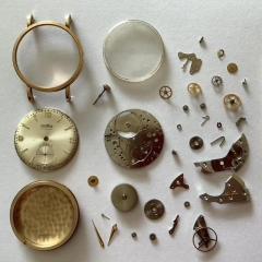
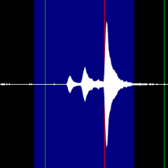
    • HWGIKE#57 Valex FEF 190 15 jewels Swiss lever full service and repair This one was waiting for a balance staff replacement in my cabinet parts and case cleaned up with a new balance staff and a 4th wheel as the original 4th wheel had a broken pivot for the off center second hand. I never attempted a balance staff replacement before however I received a Bergeon Molfres (i was hunting it for about 2 years) and with the help of it I managed to remove the old staff and riveted the new one in. It also received a new MS, crystal and the hole for the MS arbor was also tightened. With the new MS now it has an acceptable performance meaning that the amplitude goes up to 280 fully wound, has an acceptable beat error and I have the two nice lines but only dial up, dial down is not as nice and I could not figure out as why. I have the two lines but the amplitude is dropping to around 230 and the lines are a bit hairy. Both dial up and dial down the lines just go up and down without seemingly any pattern. I cleaned the movement two times, and then a 3rd time pegged out the main plate and train bridge holes but made no change. Both the HS collet and the roller table was too lose on the new staff... I did not count how many times I took the balance cock off to sort out the HS collet, the roller table and the beat error, somebody before me also shortened the HS by pushing it out a bit and it seems every time somebody is messing with the end of the HS the protruding bit is most of the time twisted bent etc. This one was probably one of the most challenging repair and service. I might take the new MS out and clean it lubricate it as I just pushed the new one in to the barrel from the retaining ring. Plus started to re-read the theory of the escapement and how to analyse the graph on the timing machine: Greiner Chronografic Record manual. I am also thinking to put the watch on a 24 hour long run with the eTimer SW it once helped me to figure out what was wrong with a watch. There is an interesting part of the Greiner record manual talking about the pallets and the end shake of the balance and pallet staff. Maybe this is my issue? Who could that possibly identify? After a few years now I am still without a clue how could watchmakers make parts I can only see with my microscope or how could/can they carry out complicated services impossible to do.. real magic..... .... ..... before I sent this post while the pics were uploading I had an idea, i was browsing the possible outcomes on the timing machine I had one for magnetism..... so I demagnetized the movement and it is not hairy now.... two really nice lines 0.2 ms beat error still a bit wavy, but a lot lot better..... argh....  
    • Hi there, welcome here.  
    • yes the advertising revenue should generate money. The question is how much money? Then as far as the cost of the website goes that's relatively easy to determine? all you would have to do to grasp costs and profitability would be to go to the link below and you can actually get a website for free try it out for free I believe you get no advertising initially. They also talk about that they'll help you out they have marketing tools and some sort of paid subscription or something. So I guess were shopping for a whatever just ask them what would a maybe could use this one as an example in other words it's going to look basically identical to this is going to have advertising a paid subscriptions what's it going to cost? After all they want to sell or give us a message board like this they should bill answer the questions as they're the people who did the software for this. Yes they really said you can have a free discussion group at least to start. https://invisioncommunity.com/ I was curious about the monthly supporter thing where exactly do we find that on this message board? A quick search I'm not finding it so obviously I'm not looking in the right place?
    • Help me out here, but with all the advertising on this site (which I don't mind) wouldn't it pay for itself or even make money for the owner ???
×
×
  • Create New...