
Slava 5498 timer rattrapante

-
Similar Content
-
-
Recently Browsing
- No registered users viewing this page.
-
Topics
-
-
Posts
-
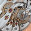
 I have been recently servicing an Omega 3220A chronograph movement which uses a Dubois Depraz 2000 chrono module. This has been quite a time consuming project, not necessarily difficult but with lots of steps. Working on the chrono module is like working on the love child of a hugely complex keyless works and a Timex pin pallet movement. I do have access to a couple of Omega tech sheets and a couple of relevant Youtube videos (including Mark Lovick's Breitling series) so I feel confident that I have all of the required information. The 'tractor' movement (effectively an ETA 2892) had no issues with obtaining 300 degree amplitude dial up / dial down and maybe a spread of 7 seconds across all of the positions. I serviced the chrono module and when reinstalling it, this brought the amplitude down to about 260 degress with the chrono stopped and 200 with it running. The Omega specification states that the chrono running should see the amplitude drop by no more than 40 degrees (from, I am guessing, the assembled amplitude i.e. chrono stopped rather than just the bare tractor movement). Obviously this isn't good enough. I am going to have to redo the chrono module again. Where I suspect I have a problem is inconsistent / over oiling of pivots. For some reason the Omega technical guide states to apply oil to the bottom pivot of each wheel and then place in the jeweled base plate. In practice, I managed to smear oil on the horizontal base of the wheel which would be smeared over the outside face of the jewel. This also wouldn't be helped by dragging the wheel around trying to get the lower pivots to engage in the the jewel. When I watch Mark service a similar Breitling chrono with DD module, he also oils the bottom pivots and installs the wheels (obviously doing a better job than me!). My question is, why can't I install the wheels dry and the oil the jewel on the other side of the base plate in the conventional way? The top pivots are oiled through the jewels in the conventional way, so why would the lower pivots be any different? Looking at the those jewels (picture below an example from a different movement) it looks like there isn't an oil well in the outside surface of the jewel around the pivot, so perhaps I would be better applying a drop of oil directly to the jewel hole before installing the wheel? Perhaps the jewels have different arrangement to conventional jewels because the outside face is installed against the dial side of the tractor movement and we don't want to risk oil migrating from the module to the movement. There are also a couple of friction springs that may have an impact on amplitude, I will recheck their pre-load but these should be OK. Is there anything else I should look at as a source of friction in the DD module?
 -
 I found a Trupoise in a flea market box of tools (🇬🇧car boot). I preferred the ‘8’ style tool until the moment I broke my new Omega rivet. The trupoise holds the arms firmly and I’ve become quite efficient… …and I just resorted to bending a balance cock. I needed a tiny bit less shake and it seemed the least risky of the other options. I held it between a stump and a fat stake while I bent the jewel end with my fingers. Honestly I don’t know how anyone would know by visual inspection.
 -

By Neverenoughwatches · Posted
It was about 4 years ago, one was 30, another 35 and 2 others came in joblots that I was after something else. 3 have ruby jewels and one has ceramic bearings.The most I've seen one sell for is £330. In the uk i still see them sell occasionally for around £70. I'm not convinced that the Trupoise has low enough friction on the pivots to be as good as a traditional tripod poising tool with unworn ruby jaws. -

By ScrewDropper · Posted
I have a Record 525 which is in a pretty bad way. From what I can see it is based on a cal 650 with an automatic bridge and centre seconds pinion under the rotor retaining stud. There are additional bearings in the train bridge for the bottom pivots of the automatic works. Of these, on has come out of the bridge completely, one is a bit mangled with an egg shaped pivot hole and one is half in, half out. I've made bearings from scratch on the lathe before, but only for pocket watch pivots (i.e. considerably bigger than these!) and these bearings are either plated or not brass, to match the bride plate, I would guess. I could not find a bridge on eBay so I started digging. I checked new Ranfft site (not help, but the new one seldom is) then the cousins download centre but I could not find a document for a cal 525. I did, however find one for the 650 and, scribbled on the page are the words "= Longines 701". So, obvious next step (or so I thought) would be to check the docs for Longines cal 701 and then see if there is maybe a cal close by, based on that cal with a rotor. I checked, no 701 in the downloads section. I did find some Longines 701 parts on eBay, which look similar to the 650 (i.e. the train bridge looks to be the same) but I feel I have hit a dead end. I have added some pictures that you may find helpful and I have photographed the entire strip down so I have more, if needed. I feel I have few options: 1. Close the brewing holes up and reinsert the loose bearings. Close up the pivot hole on the 3rd bearing and hope that does the trick. 2. Make some new bearings (doable but tricky and will look wrong) 3. hold out for a 525 bridge to come up online. I get the feeling this is a rare movement though (all the more a shame it is in such a bad condition) 5. See if there is a Longines equivalent and either use that, or transplant the bearings from that bridge to the Record. Any help identifying the Longines equivalent (if it exists) would be appreciated. Any suggestions on the alternatives I have discussed are also welcome -
 Really you paid that little for a legit Trupoise?
-


Recommended Posts